Hydraulik Broschüre_GB - MANN+HUMMEL
Hydraulik Broschüre_GB - MANN+HUMMEL
Hydraulik Broschüre_GB - MANN+HUMMEL

Create successful ePaper yourself
Turn your PDF publications into a flip-book with our unique Google optimized e-Paper software.
Filter glossary<br />
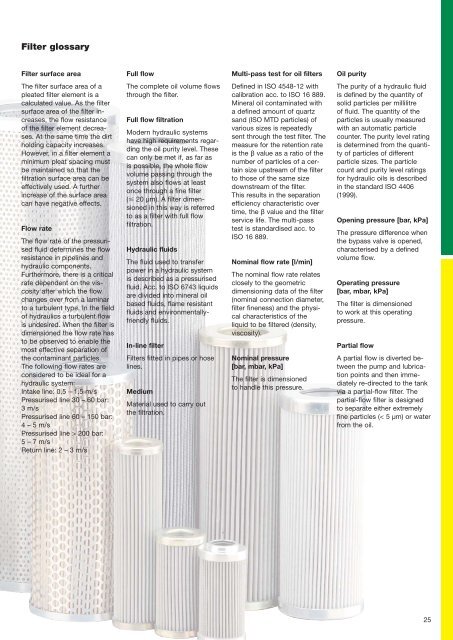
Filter surface area<br />
The filter surface area of a<br />
pleated filter element is a<br />
calculated value. As the filter<br />
surface area of the filter increases,<br />
the flow resistance<br />
of the filter element decreases.<br />
At the same time the dirt<br />
holding capacity increases.<br />
However, in a filter element a<br />
minimum pleat spacing must<br />
be maintained so that the<br />
filtration surface area can be<br />
effectively used. A further<br />
increase of the surface area<br />
can have negative effects.<br />
Full flow<br />
The complete oil volume flows<br />
through the filter.<br />
Multi-pass test for oil filters<br />
Defined in ISO 4548-12 with<br />
calibration acc. to ISO 16 889.<br />
Mineral oil contaminated with<br />
a defined amount of quartz<br />
sand (ISO MTD particles) of<br />
various sizes is repeatedly<br />
sent through the test filter. The<br />
measure for the retention rate<br />
is the β value as a ratio of the<br />
number of particles of a certain<br />
size upstream of the filter<br />
to those of the same size<br />
downstream of the filter.<br />
This results in the separation<br />
efficiency characteristic over<br />
time, the β value and the filter<br />
service life. The multi-pass<br />
test is standardised acc. to<br />
ISO 16 889.<br />
Oil purity<br />
The purity of a hydraulic fluid<br />
is defined by the quantity of<br />
solid particles per millilitre<br />
of fluid. The quantity of the<br />
particles is usually measured<br />
with an automatic particle<br />
counter. The purity level rating<br />
is determined from the quantity<br />
of particles of different<br />
particle sizes. The particle<br />
count and purity level ratings<br />
for hydraulic oils is described<br />
in the standard ISO 4406<br />
(1999).<br />
Flow rate<br />
The flow rate of the pressurised<br />
fluid determines the flow<br />
resistance in pipelines and<br />
hydraulic components.<br />
Furthermore, there is a critical<br />
rate dependent on the viscosity<br />
after which the flow<br />
changes over from a laminar<br />
to a turbulent type. In the field<br />
of hydraulics a turbulent flow<br />
is undesired. When the filter is<br />
dimensioned the flow rate has<br />
to be observed to enable the<br />
most effective separation of<br />
the contaminant particles.<br />
The following flow rates are<br />
considered to be ideal for a<br />
hydraulic system:<br />
Intake line: 0.5 – 1.5 m/s<br />
Pressurised line 30 – 60 bar:<br />
3 m/s<br />
Pressurised line 60 – 150 bar:<br />
4 – 5 m/s<br />
Pressurised line > 200 bar:<br />
5 – 7 m/s<br />
Return line: 2 – 3 m/s<br />
Full flow filtration<br />
Modern hydraulic systems<br />
have high requirements regarding<br />
the oil purity level. These<br />
can only be met if, as far as<br />
is possible, the whole flow<br />
volume passing through the<br />
system also flows at least<br />
once through a fine filter<br />
( 20 µm). A filter dimensioned<br />
in this way is referred<br />
to as a filter with full flow<br />
filtration.<br />
Hydraulic fluids<br />
The fluid used to transfer<br />
power in a hydraulic system<br />
is described as a pressurised<br />
fluid. Acc. to ISO 6743 liquids<br />
are divided into mineral oil<br />
based fluids, flame resistant<br />
fluids and environmentallyfriendly<br />
fluids.<br />
In-line filter<br />
Filters fitted in pipes or hose<br />
lines.<br />
Medium<br />
Material used to carry out<br />
the filtration.<br />
Nominal flow rate [l/min]<br />
The nominal flow rate relates<br />
closely to the geometric<br />
dimensioning data of the filter<br />
(nominal connection diameter,<br />
filter fineness) and the physical<br />
characteristics of the<br />
liquid to be filtered (density,<br />
viscosity).<br />
Nominal pressure<br />
[bar, mbar, kPa]<br />
The filter is dimensioned<br />
to handle this pressure.<br />
Opening pressure [bar, kPa]<br />
The pressure difference when<br />
the bypass valve is opened,<br />
characterised by a defined<br />
volume flow.<br />
Operating pressure<br />
[bar, mbar, kPa]<br />
The filter is dimensioned<br />
to work at this operating<br />
pressure.<br />
Partial flow<br />
A partial flow is diverted between<br />
the pump and lubrication<br />
points and then immediately<br />
re-directed to the tank<br />
via a partial-flow filter. The<br />
partial-flow filter is designed<br />
to separate either extremely<br />
fine particles (< 5 µm) or water<br />
from the oil.<br />
25