Low cycle fatigue of pseudoelastic NiTi alloys - Gruppo Italiano ...
Low cycle fatigue of pseudoelastic NiTi alloys - Gruppo Italiano ...
Low cycle fatigue of pseudoelastic NiTi alloys - Gruppo Italiano ...

You also want an ePaper? Increase the reach of your titles
YUMPU automatically turns print PDFs into web optimized ePapers that Google loves.
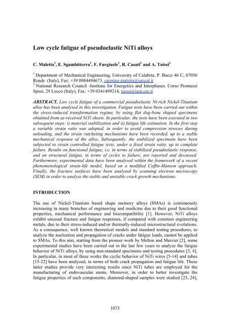
<strong>Low</strong> <strong>cycle</strong> <strong>fatigue</strong> <strong>of</strong> <strong>pseudoelastic</strong> <strong>NiTi</strong> <strong>alloys</strong><br />
C. Maletta 1 , E. Sgambitterra 1 , F. Furgiuele 1 , R. Casati 2 and A. Tuissi 2<br />
1<br />
Department <strong>of</strong> Mechanical Engineering, University <strong>of</strong> Calabria, P. Bucci 46 C, 87036<br />
Rende (Italy), Fax: +39 0984494673, carmine.maletta@unical.it<br />
2<br />
National Research Council -Institute for Energetics and Interphases. Corso Promessi<br />
Sposi, 29 Lecco (Italy), Fax: +39 0341499214, tuissi@ieni.cnr.it<br />
ABSTRACT. <strong>Low</strong> <strong>cycle</strong> <strong>fatigue</strong> <strong>of</strong> a commercial <strong>pseudoelastic</strong> Ni-rich Nickel-Titanium<br />
alloy has been analysed in this investigation. Fatigue tests have been carried out within<br />
the stress-induced transformation regime, by using flat dog-bone shaped specimens<br />
obtained from as-received <strong>NiTi</strong> sheets. In particular, the tests have been executed in two<br />
subsequent steps: i) material stabilization and ii) <strong>fatigue</strong> life estimation. In the first step<br />
a variable strain ratio was adopted, in order to avoid compression stresses during<br />
unloading, and the strain ratcheting mechanisms have been recorded, up to a stable<br />
mechanical response <strong>of</strong> the alloy. Subsequently, the stabilized specimens have been<br />
subjected to strain controlled <strong>fatigue</strong> tests, under a fixed strain ratio, up to complete<br />
failure. Results on functional <strong>fatigue</strong>, i.e. in terms <strong>of</strong> stabilized <strong>pseudoelastic</strong> response,<br />
and on structural <strong>fatigue</strong>, in terms <strong>of</strong> <strong>cycle</strong>s to failure, are reported and discussed.<br />
Furthermore, experimental data have been analysed within the framework <strong>of</strong> a recent<br />
phenomenological strain-life model, based on a modified C<strong>of</strong>fin-Manson approach.<br />
Finally, the fracture surfaces have been analysed by scanning electron microscopy<br />
(SEM) in order to analyse the stable and unstable crack growth mechanisms.<br />
INTRODUCTION<br />
The use <strong>of</strong> Nickel-Titanium based shape memory <strong>alloys</strong> (SMAs) is continuously<br />
increasing in many branches <strong>of</strong> engineering and medicine due to their good functional<br />
properties, mechanical performance and biocompatibility [1]. However, <strong>NiTi</strong> <strong>alloys</strong><br />
exhibit unusual fracture and <strong>fatigue</strong> responses, if compared with common engineering<br />
metals, due to their stress-induced and/or thermally-induced microstructural evolutions.<br />
As a consequence, well known theoretical models and standard testing procedures, to<br />
analyze the nucleation and propagation <strong>of</strong> cracks under <strong>fatigue</strong> loads, cannot be applied<br />
to SMAs. To this aim, starting from the pioneer work by Melton and Mercier [2], some<br />
experimental studies have been carried out in the last few years to analyze the <strong>fatigue</strong><br />
behavior <strong>of</strong> <strong>NiTi</strong> <strong>alloys</strong>, by using non-standard specimens and testing procedures [3, 4].<br />
In particular, in most <strong>of</strong> these works the cyclic behavior <strong>of</strong> <strong>NiTi</strong> wires [5-14] and tubes<br />
[15-22] have been analyzed, in terms <strong>of</strong> both crack propagation and <strong>fatigue</strong> life. These<br />
latter studies provide very interesting results since <strong>NiTi</strong> tubes are employed for the<br />
manufacturing <strong>of</strong> endovascular stents. Moreover, in order to better investigate the<br />
<strong>fatigue</strong> properties <strong>of</strong> such components, diamond-shaped samples were studied [23, 24],<br />
1073
with geometry very close to the unit cell <strong>of</strong> a stent. Furthermore, other studies have been<br />
devoted to the analysis <strong>of</strong> the functional <strong>fatigue</strong> <strong>of</strong> single crystal <strong>NiTi</strong> <strong>alloys</strong> [25, 26] by<br />
using special test specimens, which have been cut along different crystallographic<br />
orientations. Unfortunately, despite the significant research interest on this topic in the<br />
last years, a direct trensfereability <strong>of</strong> the <strong>fatigue</strong> results to the engineering community is<br />
not possible, as <strong>fatigue</strong> properties <strong>of</strong> <strong>NiTi</strong> <strong>alloys</strong> are significalty affected by the stress<br />
and/or thermally induced phase transition mechanisms. As a consequence, well known<br />
theories for <strong>fatigue</strong> life estimation <strong>of</strong> common metallic <strong>alloys</strong> cannot be directly applied.<br />
In this context, the present study is focused on the low <strong>cycle</strong> <strong>fatigue</strong> <strong>of</strong> a <strong>pseudoelastic</strong><br />
<strong>NiTi</strong> sheet in the stress-induced transformation regime, i.e. with maximum deformations<br />
within the transformation plateau <strong>of</strong> the alloy. The tests have been carried out in two<br />
subsequent steps: i) material stabilization and ii) <strong>fatigue</strong> life estimation. In the first step<br />
a variable strain ratio was adopted, in order to avoid compression stresses during<br />
unloading, and the strain ratcheting mechanisms have been recorded, up to a stable<br />
mechanical response <strong>of</strong> the alloy. Subsequently, the stabilized specimens have been<br />
subjected to strain controlled <strong>fatigue</strong> tests, under a fixed strain ratio, up to complete<br />
failure. Results on functional <strong>fatigue</strong>, i.e. in terms <strong>of</strong> stabilized <strong>pseudoelastic</strong> response,<br />
and on structural <strong>fatigue</strong>, in terms <strong>of</strong> <strong>cycle</strong>s to failure, are reported and discussed.<br />
Furthermore, experimental data have analysed within the framework <strong>of</strong> a recent<br />
phenomenological strain-life model [27], based on a modified C<strong>of</strong>fin-Manson approach.<br />
Finally, the fracture surfaces have been analysed by scanning electron microscopy<br />
(SEM) in order to evaluate the stable and unstable crack growth mechanisms.<br />
MATERIAL AND EXPERIMENTAL METHODS<br />
A commercial <strong>pseudoelastic</strong> Ni-rich <strong>NiTi</strong> sheet (50.8at.% Ni - 49.2 at.% Ti, Memry,<br />
Germany) with thickness t=1.5 mm, has been analyzed. Dog bone shaped specimens,<br />
with rectangular cross section (1.5mm x 3.5 mm) and with a gauge length <strong>of</strong> 10 mm,<br />
have been made from as received sheets, by wire electro discharge machining. A<br />
successive polishing procedure <strong>of</strong> the machined surfaces was carried out, by sandpapers<br />
with progressively finer grits (#400-#1200) and diamond compound (5 µm). Fatigue test<br />
have been carried out, under isothermal condition (T=298 K) by using a universal<br />
testing machine (Instron 8500) equipped with a climatic chamber (MTS 651). Figure 1<br />
shows a schematic depiction <strong>of</strong> the stress-strain behavior <strong>of</strong> a <strong>pseudoelastic</strong> <strong>NiTi</strong> alloy<br />
together with the values <strong>of</strong> the measured mechanical parameters, in terms <strong>of</strong> Young’s<br />
moduli (E A , E M ), transformation stresses (σ ! !" , σ ! !" , σ ! !" , σ ! !" ) and transformation<br />
strain (ε ! ). Furthermore, the figure schematically shows the elastic and inelastic strain<br />
range (Δε ! , Δε ! ) corresponding to the applied total strain range (Δε) in the strain<br />
controlled <strong>fatigue</strong> tests. However, due to the cyclic creep-like behavior <strong>of</strong> <strong>NiTi</strong> <strong>alloys</strong>,<br />
which causes the accumulation <strong>of</strong> residual deformations in the first mechanical <strong>cycle</strong>s<br />
(δε !"# ! ), as illustrated in Fig. 2, <strong>fatigue</strong> tests have been carried out in two subsequent<br />
steps: 1) Material stabilization and 2) Fatigue life estimation. In particular, in the first<br />
step a variable strain ratio was adopted, in order to avoid compression stresses during<br />
1074
unloading, and the strain ratcheting mechanisms have been analyzed up to a stable<br />
mechanical response <strong>of</strong> the alloy corresponding to N s <strong>cycle</strong>s, namely the number <strong>of</strong><br />
<strong>cycle</strong>s to material stabilization.<br />
Figure 1. Schematic depiction <strong>of</strong> the stress strain behavior <strong>of</strong> the pseudo elastic <strong>NiTi</strong><br />
alloy together with the main measured mechanical parameters.<br />
Figure 2. Schematic depiction <strong>of</strong> the evolution <strong>of</strong> the stress-strain hysteresis loop under<br />
cyclic loadings at fixed values <strong>of</strong> maximum strain.<br />
The tests have been carried out with maximum strain (ε !"# ) within the stress-strain<br />
transformation plateau, i.e. in the range 0.7-4.5%, and the stabilized values <strong>of</strong> the<br />
residual strain and the recovery strain, ε !"# and ε !"# respectively, have been recorded<br />
(see Fig. 2). In the second step, the specimens have been subjected to strain controlled<br />
<strong>fatigue</strong> <strong>cycle</strong>s at a frequency <strong>of</strong> 0.5 Hz, under a fixed strain ratio and with a strain range<br />
∆ε = 2 ε ! , up to complete failure and the corresponding number <strong>of</strong> <strong>cycle</strong>s N f has been<br />
recorded.<br />
1075
RESULTS AND DISCUSSION<br />
Functional <strong>fatigue</strong><br />
The cyclic creep-like mechanisms occurring during the first N s mechanical <strong>cycle</strong>s,<br />
mainly due to the formation and accumulation <strong>of</strong> residual martensite, can be considered<br />
as a functional <strong>fatigue</strong> damage phenomenon, as it causes a decrease <strong>of</strong> the <strong>pseudoelastic</strong><br />
recovery capability <strong>of</strong> the alloy. An accurate knowledge <strong>of</strong> this functional degradation is<br />
essential for the design <strong>of</strong> <strong>NiTi</strong> based components as they are normally subjected to<br />
repeated thermo-mechanical <strong>cycle</strong>s. Figure 3 illustrates the stabilized recovery and<br />
residual deformations (ε !"# and ε !"# ) as a function <strong>of</strong> the maximum applied strain<br />
(ε !"# ), in a log-log diagram.<br />
Figure 3. Stabilized residual strain and recovered strain (ε !"# and ε !"# ) as a function <strong>of</strong><br />
the applied maximum strain (ε !"# ).<br />
As expected the figure shows that ε !"# increases with increasing the maximum strain,<br />
from about 0.02% at ε !"# = 0.7% to 1.24% at ε !"# = 4.5%, and, consequently, the<br />
recovery strain, ε !"# , ranges between 0.68% and 3.26% (ε !"# = ε !"# − ε !"# ).<br />
Furthermore, the figure shows that experimental data are well approximated by straight<br />
lines in the log-log diagram and, consequently, ε !"# and ε !"# can be expressed by:<br />
!<br />
ε !"# = Aε !"#<br />
(1)<br />
!<br />
ε !"# = Bε !"#<br />
(2)<br />
where the coefficients A and B and the exponents a and b are given in Fig. 3. In<br />
addition, the number <strong>of</strong> <strong>cycle</strong>s to material stabilization, N s , is mainly unaffected by the<br />
maximum applied strain and it is in range between 100 and 150.<br />
Structural <strong>fatigue</strong><br />
Fatigue data have been analyzed within the framework <strong>of</strong> a recent literature approach<br />
[27] which is based on a modified C<strong>of</strong>fin-Manson relationship [28]. In particular, as<br />
1076
illustrated in Fig. 1, the total strain range, ∆ε, can be decomposed in the elastic strain,<br />
∆ε ! , and inelastic strain, ∆ε ! , which can be regarded as the <strong>pseudoelastic</strong> recovery:<br />
∆ε = ∆ε ! + ∆ε ! (3)<br />
where the elastic strain is calculated based on the assumption <strong>of</strong> linear evolution <strong>of</strong> the<br />
martensite fraction, ξ ! , along the stress-strain transformation plateau [29] and on the<br />
use <strong>of</strong> the Reuss’s formula [30] to estimate the Young’s modulus, E(ξ ! ), (see Fig. 1):<br />
∆ε ! = ∆σ E(ξ ! ) (4)<br />
In addition, eq. 3 can be expressed as a function <strong>of</strong> the strain amplitudes (ε ! = ∆ε 2):<br />
ε ! = ε !" + ε !" (5)<br />
Figure 4 illustrates the elastic, inelastic and total strain amplitude (ε !" , ε !" and ε ! ) as a<br />
function <strong>of</strong> the number <strong>of</strong> <strong>cycle</strong> reversals to failure (2N f ) in a log-log diagram.<br />
Figure 4. Modified C<strong>of</strong>fin-Manson approach.<br />
Furthermore, the figure shows that both elastic and inelastic strain amplitude (ε !" and<br />
ε !" ) are well approximated by straight lines in the log-log diagram and, consequently,<br />
the two strain components can be expressed by a power law relations in the ε ! − 2 N !<br />
diagram, likewise to C<strong>of</strong>fin-Manson approach in common engineering metals.<br />
In particular, the total strain amplitude, ε ! , can be related to the <strong>cycle</strong> reversals to<br />
failure, 2N ! , based on a modified C<strong>of</strong>fin-Manson approach:<br />
ε ! = ε !" + ε !" = C (2N ! ) ! + D (2N ! ) ! (6)<br />
where the coefficients C and D and the exponents c and d obtained from the<br />
experiments are reported in Fig. 4. It is worth noting that these values have been<br />
1077
obtained from a fitting <strong>of</strong> the experimental data reported in this investigation, i.e. they<br />
are related to specific specimen geometry and loading conditions and, consequently,<br />
they should be considered as testing parameters. However, the transferability <strong>of</strong> the<br />
proposed model to the engineering community, i.e. to predict <strong>fatigue</strong> life under generic<br />
loading conditions, requires further systematic experimental tests. Furthermore, the<br />
results presented in this paper have been obtained with maximum deformation within<br />
the stress-induced transformation regime and, consequently, the <strong>fatigue</strong> response <strong>of</strong> the<br />
material in the full austenitic and martensitic regions has not been investigated.<br />
SEM analyses <strong>of</strong> the fracture surfaces<br />
In Fig. 5 are depicted the SEM micrographs <strong>of</strong> the fracture surfaces obtained by testing<br />
the samples at different values <strong>of</strong> maximum deformation (a. 0,7%, b. 1,3%, c. 1,45%, d.<br />
1,7%). The analysis revealed that crack initiation occurs at the lateral surface <strong>of</strong> the<br />
specimens, as a consequence <strong>of</strong> the surface defects produced by the cutting process. In<br />
fact, these irregularities lead to local stress concentrations and act as preferable<br />
nucleation sites. Furthermore, fracture surfaces show two distinct regions characterized<br />
by different morphologies. In particular, the right part <strong>of</strong> the surfaces in the SEM<br />
micrographs <strong>of</strong> Fig. 5 are characterized by <strong>fatigue</strong> striations, which are attributed to the<br />
stable crack growth resulting from <strong>fatigue</strong> loads, while the left sides show dimples<br />
structures typical <strong>of</strong> ductile overload fractures. In addition, as expected, the stable crack<br />
penetration area decreases with increasing <strong>of</strong> the maximum applied deformation,<br />
ranging from about 2.8 mm at ε !"# = 0.7% to 0.8 mm at ε !"# = 1.7%.<br />
CONCLUSION<br />
Strain controlled <strong>fatigue</strong> tests <strong>of</strong> a commercial <strong>pseudoelastic</strong> <strong>NiTi</strong> alloy, have been<br />
carried out within the stress-induced transformation regime. Both functional and<br />
structural <strong>fatigue</strong> have been analyzed, i.e. the evolution <strong>of</strong> the <strong>pseudoelastic</strong> capability<br />
and the <strong>cycle</strong>s to failure. The results revealed a degradation <strong>of</strong> the <strong>pseudoelastic</strong><br />
recovery, during the first mechanical <strong>cycle</strong>s, and this effect becomes more evident when<br />
increasing the strain amplitude. However, a stable functional response is always<br />
observed after the first stabilization <strong>cycle</strong>s, which occurs between 100 and 150 <strong>cycle</strong>s.<br />
Furthermore, structural <strong>fatigue</strong> data have been analyzed by a novel strain-life model,<br />
based on a modified C<strong>of</strong>fin-Manson approach. Finally, fracture surfaces have been<br />
analyzed by SEM observation in order to study the stable and unstable crack growth<br />
mechanisms. However, future experimental tests should be carried out to validate the<br />
model and, consequently, to allow a direct transferability <strong>of</strong> the <strong>fatigue</strong> data to the<br />
engineering community.<br />
ACKNOWLEDGMENT<br />
The authors wish to thank Giordano Carcano (CNR IENi Lecco) for SEM technical<br />
assistance.<br />
1078
1 2<br />
1 2<br />
20µm<br />
20µm<br />
200µm<br />
a)<br />
2<br />
1 2<br />
1<br />
20µm 40µm<br />
200µm<br />
b)<br />
1<br />
2<br />
1 2<br />
20µm 40µm<br />
200µm<br />
c)<br />
1 2<br />
1<br />
2<br />
20µm 40µm<br />
200µm<br />
d)<br />
Figure 5. SEM micrographs <strong>of</strong> the fracture surfaces with highlight <strong>of</strong> the stable (right)<br />
and unstable (left) crack growth path obtained from specimens tested at different values<br />
<strong>of</strong> maximum deformation: a) 0.7%, b) 1.3%, c) 1.45% and d) 1.7%.<br />
1079
REFERENCES<br />
1. Otsuka, K., Ren, X. (2005) Progr. Mater. Sci. 50, 511-678<br />
2. Melton, K.N., Mercier, O. (1979) Acta Metall. 27, 137-144<br />
3. Hornbogen, E. (2004) J. Mater. Sci. 39, 385-399<br />
4. Pelton, A.R. (2011) J. Mater. Eng. Perform. 20, 613-617<br />
5. Miyazaki, S., Imai, T., Igo, Y., Otsuka, K. (1986) Metall. Trans A. 17, 115-120<br />
6. Tobushi, H., Shimeno, Y., Hachisuka, T., Tanaka, K. (1998) Mech. Mater. 30, 141-150<br />
7. Lagoudas, D.C., Miller, D.A., Rong, L., Kumar, P.K. (2009) Smart Mater. Struct. 18<br />
art no. 085021<br />
8. Soul, H., Isalgue, A., Yamny, A., Torra, V., Lovey, F.C. (2010) Smart Mater. Struct.<br />
19, 1-7<br />
9. Dolce, M., Cardone, D. (2001) Int. J. Mech. Sci. 43, 2657-2677<br />
10. Miyazaki, S., Mizukoshi, K., Ueki, T., Sakuma, T., Liu, Y. (1999) Mater. Sci. Eng.<br />
A273–275, 658-663<br />
11. Tobushi, H., Nakahara, T., Shimeno, Y., Hashimoto, T. (2000) J. Eng. Mater-T ASME.<br />
122, 186-191<br />
12. Eggeler, G., Hornbogen, E., Yawny, A., Heckmann, A., Wagner, M. (2004) Mater. Sci.<br />
Eng. A 378, 24-33<br />
13. Figueiredo, A.M., Modenesi, P., Buono, V. (2009). J. Fatigue. 31, 751-758<br />
14. Norwich, D.W., Fasching, A. (2009) J. Mater. Eng. Perform. 18, 558-562<br />
15. Nemat-Nasser, S., Guo, W.G. (2006) Mech. Mater. 38, 463–474<br />
16. Kang, G., Kan, Q., Yu, C., Song, D., Liu, Y. (2012) Mater. Sci. Eng. A 535, 228– 234<br />
17. Casciati, S., Marzi, A. (2011) Eng. Struct. 33, 1232–1239<br />
18. McKelvey, A.L., Ritchie, R.O. (1999) J. Biomed. Mater. Res. 47, 301-308<br />
19. McKelvey, A.L., Ritchie, R.O. (2001) Metall. Mater. Trans. A. 32A, 731-743<br />
20. Tabalni, R.M., Simha, N.K., Berg, B.T. (2001) Metall. Mater. Trans. A. 32A, 1866-<br />
1869<br />
21. Runciman, A., Xu, D., Pelton, A.R., Ritchie, R.O. (2011) Biomaterials. 32, 4987-4993<br />
22. Moumni, Z., Van Herpen, A., Riberty, P. (2005) Smart Mater. Struct. 14, 287–292<br />
23. Pelton, A.R., Gong, X.Y., Duerig, T. (2003) Medical Device Materials – Proceedings<br />
<strong>of</strong> the Materials and the Processes for Medical Devices Conference 2003, 199-204<br />
24. Pelton, A.R., Schroeder, V., Mitchell, M.R., Gong, X.Y., Barney, M., Robertson, S.W.<br />
(2008) J. Mech Behav Biomed. 1, 153-164<br />
25. Gall, K., Sehitoglu, H., Chumlyakov, Y.I., Kireeva, I.V. (1999) Scripta Mater. 40(1),<br />
7–12<br />
26. Sehitoglu, H., Anderson, R., Karaman, I., Gall, K., Chumlyakov, Y. (2001) Mater. Sci.<br />
Eng. A 314, 67–74.<br />
27. Maletta, C., Furgiuele, F., Sgambitterra, E. (2012), Fatigue <strong>of</strong> <strong>pseudoelastic</strong> <strong>NiTi</strong><br />
within the stress-induced transformation regime: a novel strain-life approach,<br />
Submitted in Smart Mater. Struct.<br />
28. Stephens, R.I., Fatemi, A., Stephens, R.R., Fuchs, H.O. (2000). In: Metal Fatigue in<br />
Engineering, (second ed.), Wiley-Interscience, New York<br />
29. Maletta, C., Falvo, A., Furgiuele, F., Reddy, J.N. (2009) Smart Mater. Struct. 18, 1–9<br />
30. Auricchio, F., Sacco, E. (1997) Int. J. NonLin. Mech. 32, 1101-1114<br />
1080