Installation instructions - Haas + Sohn
Installation instructions - Haas + Sohn
Installation instructions - Haas + Sohn

Create successful ePaper yourself
Turn your PDF publications into a flip-book with our unique Google optimized e-Paper software.
Check:<br />
For the setup to be checked the boiler must be brought to a temperature of 70°C and the<br />
chimney to operating temperature i.e. it must contain the full stored heat. From<br />
experience, the full stored heat of the chimney (fireplace, flue) is achieved after the<br />
following minimum operating period:<br />
Metal fireplace:<br />
30 minutes<br />
Insulated multi-skinned fireplace: 5 hours<br />
Brick or stone-built fireplace: 6 hours<br />
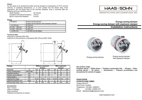
Sizing<br />
Fireplace<br />
Energy-saving damper<br />
Energy-saving damper with explosion damper<br />
< Ø 130 mm Ø 130 mm<br />
Ø 130 – 160 mm Ø 150 mm<br />
Ø 160 – 250 mm Ø 200 mm<br />
> Ø 250 mm 2 x Ø 200 mm (fit offset)<br />
Energy-saving damper<br />
Energy-saving damper with explosion damper<br />
<strong>Installation</strong> <strong>instructions</strong><br />
Technical data:<br />
Inspected to standard DIN 4795<br />
Conforms to the provisions of standards DIN 4705 and DIN 18160<br />
Energy-saving damper<br />
Energy-saving damper<br />
with explosion damper<br />
Design<br />
Without explosion<br />
damper<br />
With explosion<br />
damper<br />
Diameter D 130 150 200 130 150 200<br />
Group classification DIN 4796 2 4 4 2 4 4<br />
Insertion length a mm 79 79 79 79 79 79<br />
Shuttle valve setting b mm 22 33 22 33<br />
Valve length c mm - - - - - -<br />
Adjustment range Pa 10-30 10-33 4-35 10-30 10-33 4-35<br />
Opening pressure min. mbar 6 6 6 6 6 6<br />
Exhaust gas temp. max. °C 400 400 400 400 400 400<br />
Accessories:<br />
Pipe T pieces<br />
Weld-on adapters<br />
Wall connectors<br />
Additional accessories on enquiry<br />
Our product range:<br />
Fireplace stoves • Pellet stoves • Fireplace construction kits • Ranges • Slowburning<br />
stoves • Oil stoves • Accessories • Pressure accumulators and<br />
accessories for central oil supply<br />
HAAS+SOHN<br />
OFENTECHNIK GMBH<br />
Urstein Nord 67<br />
5412 Puch, Austria<br />
Telephone: +43 662 / 44955-0<br />
Fax: +43 662 / 44955-210<br />
Email: ofentechnik@haassohn.com<br />
www.haassohn.com
Operation:<br />
The HAAS+SOHN energy-saving damper constantly evens out the changes in the draught<br />
in the chimney that may be caused by external weather conditions (cold, wind). If the<br />
draught in the chimney becomes too strong, the shuttle valve opens and air flows into the<br />
chimney from the heating chamber. The low pressure (fireplace draught) at the boiler<br />
therefore remains constant, permitting optimum combustion. Even when the system is not<br />
operating the shuttle valve opens, ventilates the chimney and thereby keeps the heat in<br />
the boiler. Constant chimney ventilation also prevents the chimney from sooting up.<br />
With the HAAS+SOHN energy-saving damper with an explosion damper, the explosion<br />
damper opens in the event of minor explosions that might occasionally occur in the boiler.<br />
In this way the short-term excess pressure is easily released and damage to the heating<br />
unit is effectively prevented.<br />
<strong>Installation</strong> <strong>instructions</strong>:<br />
HAAS+SOHN energy-saving dampers are very easy to install. <strong>Installation</strong> and setting<br />
should nevertheless be done by an expert. Thereafter the HAAS+SOHN energy-saving<br />
damper is maintenance-free. Even retrofitting into an existing heating unit is possible<br />
without problems.<br />
HAAS+SOHN energy-saving dampers may only be installed in exhaust gas pipework,<br />
ideally in the exhaust gas pipe between the fire and the chimney (fireplace, flue).<br />
The further the HAAS+SOHN energy-saving damper is from the fire’s exhaust gas<br />
adapter, the more the most frequently occurring damping and vibration problems must be<br />
taken into account during adjustment.<br />
The installation of the HAAS+SOHN energy-saving damper should be in the room in which<br />
the fire is installed and must not be done in especially hazardous rooms (living rooms and<br />
bedrooms, food storage rooms and rooms with a higher fire risk).<br />
Important during installation:<br />
The front of the energy-saving damper must always be placed in a vertical position, the<br />
axis of the shuttle valve in a horizontal one.<br />
The supply pressure (draught required) for the relevant fire should be set by an expert.<br />
B) <strong>Installation</strong> with weld-on adapter in the gas pipe:<br />
The weld-on adapter permits space-saving<br />
installation of the damper. Determine the<br />
installation site, line up the weld-on adapter<br />
vertically and mark the cutout on the exhaust<br />
gas pipe. Make the cutout and weld the weldon<br />
adapter firmly in place. Push in the damper<br />
and set the axis of the shuttle valve to the<br />
horizontal. The damper is to be secured<br />
against slipping in the weld-on adapter.<br />
<strong>Installation</strong> with weld-on adapter<br />
C) <strong>Installation</strong> with wall connector in the chimney<br />
(not possible with D 130 mm):<br />
Before installation in the chimney you should consult the relevant flue<br />
sweep or chimney sweep and possibly the chimney manufacturer<br />
regarding the correct way to open up the fireplace masonry.<br />
A wall connector is built in flush with the plaster for installation. Insert the<br />
energy-saving damper, set the axis of the shuttle valve to the horizontal<br />
and secure against slipping.<br />
<strong>Installation</strong> with<br />
wall connector<br />
ATTENTION: When commissioning: In operating mode attach the securing latch as per<br />
the diagram below! The shuttle valve must be free to move!<br />
Adjustment:<br />
Adjustment is made by rotating and fixing the tare weights. This allows the supply<br />
pressure (draught) required by the fire to be precisely set by means of the appropriate<br />
positioning of the tare weights. If there is no flow meter available, the valve should be set<br />
at 30° to the vertical. (On this see also the specified dimensions in the technical data or<br />
the sketches below for the D 130 mm design).<br />
Fix the tare weights with the integral grub screw after setup.<br />
<strong>Installation</strong>:<br />
A) <strong>Installation</strong> with T piece in the flue tube:<br />
With this, installation can be quickly and correctly carried out, especially with new units.<br />
Determine the installation site, take into account the installed length of the T piece in<br />
terms of space requirements and insert the appropriate T<br />
piece in such a way that the branch pipe is vertical to the<br />
front. Attach with clamps or by welding. With existing units,<br />
the length of the T piece is cut out of the existing exhaust<br />
gas pipe and the T piece is inserted as described above.<br />
Push in the damper and set the axis of the shuttle valve to<br />
the horizontal. The damper is to be secured against slipping<br />
in the T piece.<br />
Securing latch<br />
Pressure adjustment<br />
<strong>Installation</strong> in the T piece<br />
Positioning the tare weights for D 130 mm