Bedienungsanleitung für HAAS + SOHN Pellet Kaminöfen
Bedienungsanleitung für HAAS + SOHN Pellet Kaminöfen
Bedienungsanleitung für HAAS + SOHN Pellet Kaminöfen

You also want an ePaper? Increase the reach of your titles
YUMPU automatically turns print PDFs into web optimized ePapers that Google loves.
Art. no. 0544108009031<br />
V13 C11<br />
Catania / Lucca Stove<br />
441.08 / 440.08<br />
Installation and operating instructions<br />
Please observe the following instructions:<br />
Quality of wood pellets:<br />
! Important manufacturer’s instructions!<br />
Depending on the manufacturer there are light, dark, shorter and longer pellets. And the quality of one delivery may<br />
differ from another even from the same supplier. The standards for wood pellets are becoming more and more strict<br />
but wood is wood and has its own characteristics regarding ash and clinker.<br />
Your <strong>HAAS</strong>+<strong>SOHN</strong> stove<br />
Cleaning requirements:<br />
As soon as you find ash and clinker deposits in the cold combustion pot, it must be cleaned. See operating<br />
instructions! If this is not done, there will be more and more clinker. Then the device will no longer be able to ignite<br />
properly. <strong>Pellet</strong>s may pile up in the combustion pot. In extreme cases, this can reach all the way back to the pellet<br />
chute. Backfire in the pellet container and smouldering in the pellet tank might possibly result. This will destroy<br />
your device and is not covered by the guarantee.<br />
For maximum working life:<br />
<br />
<br />
<br />
Arrange for commissioning by your trained stove supplier.<br />
Observe the daily check as described and more frequently if you have received new pellet deliveries or when<br />
the device is brought back into use after the summer.<br />
Carefully read through all the operating instructions and retain them.<br />
Space for type number and manufacturer’s number:<br />
Type number:<br />
Manufacturer’s number:
Index of contents<br />
1. Description 3<br />
2. General instructions, safety instructions 3<br />
3. Installation of the pellet stove and connection to<br />
the chimney 4<br />
4. The pellet stove’s functional characteristics 6<br />
5. The pellet stove’s operating statuses: 6<br />
5.1. Ignition phase 6<br />
5.2. Heating mode 6<br />
5.3. Burner test 7<br />
5.4. Cooling down 7<br />
5.5. Standby 7<br />
5.6. Safety shutdown (shutdown) 7<br />
5.7. Faults 7<br />
5.8. Switching off – operating status OFF 8<br />
5.9. Power cut 8<br />
5.10. Overheating 8<br />
5.11. Low temperature shutdown 8<br />
6. Description of operator console keys 8<br />
6.1. Operator console 8<br />
6.2. Information screens 9<br />
6.2..1 Info screen 1 (Standard screen) 9<br />
6.2..2 Main menu 9<br />
6.2..3 Setting the operating mode 9<br />
6.2..4 Setting the time and date 9<br />
6.2..5 Setting the times and target room temperatures<br />
in automatic mode 9<br />
6.2..6 Setting target room temperature in Heating<br />
mode 9<br />
6.2..7 Fault screen 10<br />
6.3. Setting the language 10<br />
6.4. Description – Heating profile 10<br />
6.5. Description – Key lock (child-safe) 10<br />
6.6. Description – Display brightness - contrast setting<br />
10<br />
7. Operating the pellet stove 10<br />
7.1. Fuel 10<br />
7.2. Commissioning your pellet stove 11<br />
7.3. Selecting the operating mode 11<br />
7.3..1 “Heating” operating mode 12<br />
7.3..2 Setting the target room temperature in<br />
“Heating” operating mode 12<br />
7.3..3 “Auto” operating mode<br />
(weekly programme) 12<br />
8. Cleaning and maintenance work 13<br />
8.1. Cleaning the surface 13<br />
8.2. Cleaning the glass panel 13<br />
8.3. Cleaning the combustion pot 13<br />
8.4. Removing the ash from the combustion chamber<br />
14<br />
8.5. Cleaning the pellet container 14<br />
8.6. Cleaning the flue gas passes and the flue tubes 15<br />
8.7. Cleaning the induced draught housing and fan 15<br />
9. Description of the components 15<br />
9.1. Storage container (pellet tank) 15<br />
9.2. Screw conveyor motor / screw conveyor 15<br />
9.3. Combustion pot with tray: 16<br />
9.4. Electric ignition 16<br />
9.5. Control unit 17<br />
9.6. Operator console 17<br />
9.6..1 Backlighting 17<br />
9.6..2 Activating the backlighting 17<br />
9.7. Induced draught fan with rotation speed feedback17<br />
9.8. Flame or combustion chamber temperature sensor<br />
(combustion chamber thermosensor) 17<br />
9.9. Flue gas thermosensor 18<br />
9.10. Room temperature sensor 18<br />
9.11. OC – Overheat cutout 18<br />
9.12. Combustion chamber cladding 18<br />
9.13. Flue tube connection 18<br />
9.14. Mains cable and master switch 18<br />
10. Options 19<br />
10.1. Parts list 19<br />
10.2. Assembly instructions GSM Module 19<br />
10.2..1 Assembly of the antenna 19<br />
10.2..2 Connection 19<br />
10.2..3 Assembly of the module 19<br />
10.3. GSM Module Setup 20<br />
10.3..1 Preparing the SIM card for operation with the<br />
GSM module 20<br />
10.3..2 Inserting the SIM card in the GSM module<br />
20<br />
10.3..3 Connecting plug-in power unit with GSM<br />
module 20<br />
10.3..4 Starting the pellet stove via mobile phone<br />
20<br />
10.4. Technical Specifications of the GSM Module<br />
20<br />
11. Technical data 21<br />
12. Faults, causes, correction 22<br />
12.1. Error messages on the display 22<br />
12.2. General faults 26<br />
13. Type plate: Symbol 28<br />
14. Replacement parts list 30<br />
15. Circuit diagram 31<br />
16. Guarantee 33<br />
2
Congratulations! You are the owner of a <strong>HAAS</strong> + <strong>SOHN</strong><br />
pellet stove, a quality product. Please read through<br />
these instructions carefully. They will tell you all about<br />
the functions and operation of this stove, which will<br />
increase the utility of this device and extend its working<br />
life. What is more, with the correct heating you can save<br />
fuel and protect the environment.<br />
We can only give a guarantee on our products if you<br />
observe the following instructions in these installation<br />
and operating instructions. In addition, the stove must be<br />
correctly installed so as to prevent possible accidents.<br />
Look after these instructions well, then you will be able<br />
to familiarise yourself with the correct operation of your<br />
stove at the start of every heating period.<br />
Note:<br />
The installation and operating instructions given in this<br />
manual may differ entirely or in part from public authority<br />
instructions. In that event, the public authority<br />
instructions always apply! The drawings in these<br />
instructions are not to scale and serve only as<br />
illustrations.<br />
2. General instructions, safety instructions<br />
<br />
Before commissioning the pellet stove read the<br />
entire installation and operating instructions through<br />
thoroughly.<br />
Only permitted handling gear with sufficient<br />
loadbearing capacity may be used for moving your<br />
device.<br />
<br />
<br />
<br />
Your heating device is not suitable for use as a<br />
ladder or mounting frame.<br />
For the installation of your stove, the fire protection<br />
authority’s regulations and the local building<br />
regulations in force at the installation site are to be<br />
observed and you should also discuss this with the<br />
district heating inspector. He will also check that the<br />
connection of the device to the fireplace is carried<br />
out correctly.<br />
All the checks required by law have been performed<br />
on your stove. The mandatory indices regarding<br />
technical combustion efficiency and flue gas<br />
emissions are observed.<br />
1. Description<br />
<strong>Pellet</strong> stoves are particularly suitable for the constant<br />
heating of residential and work rooms. The<br />
<strong>HAAS</strong>+<strong>SOHN</strong> pellet stove is set up to operate in fully<br />
automatic mode, with a choice of 2 operating modes<br />
(“Heating” and “Auto” with a weekly programme).<br />
Depending on the room temperature and on the model,<br />
a volume of fuel for a maximum of 50 hours of constant<br />
operation may be stored in the built-in storage container.<br />
The fuel is fed automatically from the pellet tank to the<br />
grate via a screw conveyor, with the quantity of fuel<br />
automatically being adjusted to the relevant heat output.<br />
The internal control unit regulates the ignition phase, the<br />
heating phase and the cooling down phase, thereby<br />
guaranteeing safe operation of the pellet stove. The<br />
operator console, which consists of a display and four<br />
function keys, is built into the pellet tank cover.<br />
On the display’s information screen the operator can<br />
read the operating status that the stove is currently in,<br />
this being displayed as text. Any error messages are<br />
shown on the display as text complete with the date and<br />
time.<br />
The heating of the air in the room and the creation of<br />
comfortable living conditions is mainly achieved by<br />
convection. This allows you to quickly warm up even<br />
cold<br />
<br />
<br />
<br />
<br />
The pellet stove may be connected to a multiple-use<br />
chimney provided that the chimney dimensions<br />
permit this according to DIN EN 13384-1 or DIN EN<br />
13384-2. The supply pressure must be at least 6<br />
Pa and should be 15 Pa as a maximum.<br />
In the case of a tightly constructed air supply<br />
duct,(room air independent operation) multiple<br />
connections to the chimney are not permitted; your<br />
stove conforms to type FC4Ix (LAS system) and<br />
FC51C in accordance with the permit conventions<br />
for room air-independent fireplaces for solid fuels. In<br />
combination with room air systems (controlled air<br />
installations, extractor hoods in kitchens, exhaust<br />
fans etc.) § 4 of the Fire Code Ordinance (FeuVo) is<br />
applicable in Germany.<br />
The combustion chamber door may be opened only<br />
for cleaning and maintenance during operating<br />
status “Off”. Otherwise it is to be kept closed – even<br />
when the stove is not operating in order to avoid<br />
affecting other heating appliances and the<br />
associated risks.<br />
An adequate supply of fresh air must be guaranteed<br />
to the room where the stove is installed. However,<br />
the pellet stove offers you the option of a direct<br />
connection to the outside air via a suitable air duct.<br />
So operation independent of the air in the room is<br />
possible. (See Section 3 “Installation of the pellet<br />
stove and connection to the chimney”).<br />
rooms that have been unheated for a lengthy period.<br />
The cooler air of the room enters the stove at the bottom<br />
of the cladding, is heated and flows out again at the top<br />
in the area of the slats. The proportion of radiant heat is<br />
given off by radiation in the area of the viewing window<br />
of the combustion chamber door and from the stove’s<br />
metal surfaces.<br />
<br />
Attention! The pellet stove may not be set<br />
up to be operated jointly with the home’s air<br />
conditioning and ventilation units.<br />
3
The chimney (fireplace or flue) must be made of<br />
stainless steel or ceramics (glazed internally) and<br />
suitable for wet operation so that it cannot rot.<br />
<br />
Clotheshorses for drying clothes and the like must<br />
be positioned at sufficient distance from the heating<br />
device – fire risk!<br />
<br />
<br />
<br />
<br />
<br />
<br />
<br />
<br />
<br />
<br />
<br />
<br />
<br />
<br />
The pellet stove cannot be connected to the mains<br />
electricity until it has been correctly connected to the<br />
fireplace.<br />
The pellet stove may not be installed in the open<br />
air!<br />
Attention! The mains cable plug must remain freely<br />
accessible after installation.<br />
The pellet stove may only be operated with standard<br />
wood pellets (6 mm diameter). (See Section 7.1<br />
“Fuel”).<br />
The protective grille located in the pellet container<br />
must not be removed.<br />
Attention! The <strong>Pellet</strong>to stove may only be<br />
operated with the tank cover closed.<br />
Placing non-heat-resistant materials or objects on<br />
the stove or within the specified minimum distances<br />
is forbidden. Here please note in particular that<br />
during “Standby” operating status, the stove may<br />
unexpectedly and unintentionally start heating when<br />
the room temperature falls below the desired<br />
temperature.<br />
Never use liquid fuels to ignite the pellet stove or to<br />
revive existing embers.<br />
With the burning up of fuels, heat energy is<br />
released, leading to strong heating of the heating<br />
device’s surfaces (e.g. doors, door and control<br />
handles, viewing window panels, side walls, front<br />
wall, flue tubes). Touching these parts without<br />
suitable heat protection gloves or a tool is to be<br />
avoided!<br />
The device ignites by itself in “Standby” mode.<br />
Because of the heat generated on the panel, make<br />
sure that no-one who is unfamiliar with the operation<br />
of the pellet stove is unsupervised in the room where<br />
it is installed.<br />
Bring these risks to your children’s and guests<br />
attention!<br />
In particular, any cleaning staff should be informed<br />
and instructed regarding the possible unexpected<br />
heating up of the stove.<br />
Placing non-heat-resistant objects on or near the<br />
heating device (even when it is cold, since it can<br />
ignite again by itself) is forbidden!<br />
Do not lay any laundry on the stove to dry!<br />
<br />
When operating your heating device, it is forbidden<br />
to work with highly flammable or explosive<br />
substances in the same room or an adjacent one!<br />
3. Installation of the pellet stove and connection to<br />
the chimney<br />
The packaging on your new pellet stove gives it optimum<br />
protection against damage. Nevertheless, damage may<br />
have occurred to the stove or to accessories in transit.<br />
Please therefore check your stove after unpacking for<br />
damage and completeness! Report any defects or<br />
anything missing to your specialist stove dealer without<br />
delay!<br />
Remark: Combustion chamber cladding that is loose or<br />
has come off its fastenings and the like are not defects.<br />
(See Section 7.2. “Commissioning your pellet stove”).<br />
The packaging on your stove is by and large<br />
environmentally neutral. The timber packaging is not<br />
untreated. The timber, the cardboard and the films can<br />
be taken without problems to your local recycling centre.<br />
For the correct operation of your pellet stove it is<br />
important that it stands horizontally.<br />
The room temperature sensor that is located on the back<br />
wall has a length of about 1.5 m and should be<br />
positioned hanging free at the back.<br />
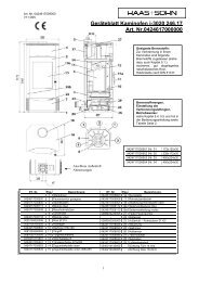
Figure 1: Back connections<br />
1 = Mains cable<br />
2 = Data cable connection<br />
3 = OC overheat cutout<br />
4 = Fume elbow 80 mm<br />
5 = Outside air connection 60 mm<br />
6 = Room temperature sensor<br />
7 = back wall<br />
4
Floor protection<br />
The floor is to be protected from the radiant heat from<br />
the area of the viewing window (combustion chamber).<br />
In addition, for practical reasons associated with<br />
cleaning it is recommended that you install your pellet<br />
stove on a fireproof base that extends beyond the device<br />
at the back and on the sides by at least 5 cm and at the<br />
front by at least 50 cm. We have floor protection plates<br />
(underlay plates or U plates) in our range of accessories.<br />
If required, you may order them from your specialist<br />
stove dealer. As an alternative, a tile or stone floor is of<br />
course very suitable.<br />
With longer flue gas pipework, horizontal sections and<br />
constrictions must be avoided and specially insulated<br />
flue tubes should be used. Pipework rising in the<br />
direction of the chimney is recommended.<br />
Safety gaps (minimum gaps):<br />
During installation of the stove it is absolutely essential<br />
to observe the official fire protection regulations. Ask<br />
your district heating inspector about this.<br />
The following must be maintained as the minimum<br />
distances from flammable or temperature-sensitive<br />
materials (e.g. furniture, wallpaper, wooden cladding)<br />
and from loadbearing walls. (See drawing):<br />
A<br />
B<br />
C<br />
2 cm from the back wall<br />
5 cm from the side walls and<br />
70 cm in the direction of radiation.<br />
Figure 3: Chimney connection<br />
1 = Wall lagging<br />
2 = Gas-tight pipework<br />
3 = Underlay plate<br />
Figure 2: Safety gaps<br />
The chimney (fireplace or flue) must for example be<br />
made of stainless steel or ceramics (glazed internally) so<br />
that it cannot rot. This is necessary because of the low<br />
temperature of flue gases from your pellet stove.<br />
Standard trade flue tubes may be used for the<br />
connection to the fireplace. Approved Flex steel flues<br />
are also suitable.<br />
Since excess pressure may build up at the smoke outlet<br />
because of the way that the pellet stove works with an<br />
induced draught fan, all fume outlet pipes as far as the<br />
intake to the fireplace must be gas-tight. It is also<br />
essential to ensure that the flue tube does not stick out<br />
into the open cross-section of the chimney. The use of<br />
wall lagging is recommended for the insertion into the<br />
chimney. (See Figure 3).<br />
External air intake:<br />
In airtight buildings, whilst the pellet stove is operating, a<br />
reduction in the oxygen level in the room where the<br />
stove is installed may occur, so adequate ventilation<br />
must be ensured. For this the pellet stove offers you the<br />
option of operating independently of the air in the room.<br />
To do this, connect the air intake elbow located on the<br />
back (diameter: 60 mm) to a hose or a similar suitable<br />
air duct. The end of the air duct must be located in the<br />
open air or in a well-ventilated room within the building.<br />
When installing the pellet stove in combination with<br />
controlled residential room ventilation, the end of the air<br />
intake duct must not be connected to the ventilation<br />
system in an adjacent room with the air connection<br />
system. To ensure sufficient volume of air intake, the<br />
pipe should not be longer than about 3 m and not have<br />
too many bends.<br />
This pipe should have a minimum diameter of 5 cm.<br />
(The bigger, the better). If the pipe goes to the open air,<br />
it must end with a downward 90° bend or with wind<br />
protection. (See Figure 4).<br />
5
5. The pellet stove’s operating statuses:<br />
The operation of the pellet stove is characterised by 8<br />
operating statuses:<br />
The ignition phase begins if the current room<br />
temperature falls below the set target temperature by<br />
1ºC and the stove has cooled down to a temperature of<br />
below 70C°.<br />
5.1. Ignition phase<br />
In the “Ignition phase” the grate is filled with a precisely<br />
defined quantity of fuel and this quantity of fuel is ignited<br />
with a glow igniter.<br />
Figure 4: Wind protection of the air intake pipe<br />
The following table applies to the sizing of the air intake<br />
pipe:<br />
Diameter of the<br />
intake pipe *<br />
Maximum<br />
length *<br />
Max. number of<br />
90° bends<br />
50 mm 0.5 m 1<br />
100 mm 1 m 1<br />
100 mm 3 m 3<br />
*The figures given apply as appropriate. With a flat duct<br />
or similar, a suitable cross-section is to be chosen.<br />
If the pipes are narrower than these dimensions, it may<br />
be that the volume of combustion air is insufficient. This<br />
will result in heavier buildup of clinker in the grate and<br />
thereby to safety shutdowns.<br />
Connection to the electricity supply:<br />
Connect the stove to the electricity supply with the mains<br />
cable supplied. (See Figure 1).<br />
4. The pellet stove’s functional characteristics<br />
Your pellet stove is designed to operate in such a way<br />
as to maintain a constant comfortable room temperature.<br />
The generation of heat in the stove is therefore<br />
automatically controlled by the desired room<br />
temperature (target temperature) set by the operator.<br />
Depending on the difference between the target<br />
temperature and the current room temperature (actual<br />
temperature) the control unit selects output or “Standby”<br />
mode in a modular fashion. So the pellet stove<br />
guarantees the best possible adjustment of the<br />
combustion behaviour of the pellet stove for the situation<br />
in the room where it is installed without constant manual<br />
corrective measures.<br />
The “Ignition phase”, which is divided into 10 zones, is<br />
ended after reaching a precisely defined temperature on<br />
the “flame temperature sensor” and the control unit<br />
switches to “Heating Mode” operating status.<br />
The duration of the “Ignition phase” may vary but it is<br />
restricted to a maximum length of about 20 minutes.<br />
If during these 20 minutes no flame is formed or the<br />
required temperature is not reached at the “flame<br />
temperature sensor – flue gas”, a safety shutdown is<br />
initiated.<br />
Here the rotation speed of the induced draught fan is<br />
constantly measured and checked by means of the<br />
rotation speed feedback.<br />
5.2. Heating mode<br />
After successful completion of the “Ignition phase”, the<br />
stove automatically switches to “Heating mode”<br />
operating status.<br />
In “Heating mode” operating status, the stove’s heat<br />
output is adjusted in modular fashion on the basis of the<br />
room temperature or the difference between the actual<br />
room temperature and the target room temperature.<br />
If there is a great difference between the target room<br />
temperature and the actual room temperature, then the<br />
stove will operate with greater heat output (maximum 8<br />
kW).<br />
The closer the actual room temperature comes to the<br />
target room temperature, the more the heat output of the<br />
stove is reduced (minimum heat output = 2.5 kW).<br />
Depending on the required heat output, the relevant<br />
quantity of fuel will be supplied at a regular rate via the<br />
pellet chute to the grate by means of the screw<br />
conveyor.<br />
During the “Heating mode” operating status, the flame or<br />
combustion chamber temperature is measured just<br />
above the flame by means of a special thermosensor<br />
whose signals are processed in the control unit and are<br />
the basis for the relationship of the “energy level in the<br />
grate” and the combustion air volume taken in, which<br />
ensures “ideal combustion” and a high level of efficiency.<br />
During the “Heating mode” operating status, the rotation<br />
speed of the induced draught fan is monitored by means<br />
of rotation speed feedback and constant comparison<br />
between the target and actual rotation speeds.<br />
6
In the event of a large difference between the actual<br />
rotation speed and the target rotation speed, a safety<br />
shutdown will be initiated and an error message is<br />
shown on the operator console display.<br />
During the “Heating mode” operating status, the<br />
maximum and minimum heat output are each controlled<br />
by safety limits (maximum and minimum flue gas<br />
temperature) i.e. if during the “Heating mode” operating<br />
status the maximum flue gas temperature is exceeded<br />
or if the flue gas temperature falls below the minimum, a<br />
safety shutdown will be initiated.<br />
5.3. Burner test<br />
Every 40 minutes during the “Heating mode” operating<br />
status, a burner test is performed.<br />
The burner test is performed regardless of the heat<br />
output currently being delivered by the stove.<br />
This process takes about 2 minutes.<br />
5.4. Cooling down<br />
If the set target room temperature is reached i.e. the<br />
actual room temperature and the target room<br />
temperature match, then the control unit switches to<br />
“Cooling down” operating status.<br />
The fuel supply is stopped i.e. the screw conveyor that is<br />
located in the screw conveyor tube, stops, the rotation<br />
speed of the induced draught fan is regulated to a<br />
precisely defined rotation speed and the fuel which is<br />
still in the grate is burnt.<br />
The cooling down phase is restricted by timing control<br />
(duration about 15 minutes).<br />
After the end of the “Cooling down” operating status, the<br />
device switches to “Standby” operating status.<br />
5.5. Standby<br />
There is no combustion process going on in this<br />
operating status, all the components, the induced<br />
draught fan and the screw conveyor are stopped, the<br />
ignition is switched off and the device is in a “waiting<br />
position.”<br />
Attention!<br />
The device starts by itself in “Standby mode”.<br />
Because of the heat generated on the panel, you<br />
must ensure that there is no-one who is unfamiliar<br />
with the operation of the pellet stove unsupervised<br />
in the room where it is installed.<br />
Placing non-heat-resistant materials or objects on<br />
the stove or within the specified minimum distances<br />
is forbidden.<br />
5.6. Safety shutdown (shutdown)<br />
If a fault occurs, regardless of in which operating status<br />
or which operating mode, a safety shutdown is initiated.<br />
The safety shutdown process is precisely defined.<br />
During the safety shutdown, the components are<br />
switched on or off as follows:<br />
Induced draught fan – ON<br />
Screw conveyor – OFF<br />
Ignition – OFF<br />
The ending of the safety shutdown is temperaturedependent<br />
i.e. the “Safety shutdown” operating status is<br />
maintained until the stove has cooled down to a flue gas<br />
temperature of below 70°C.<br />
Once the safety shutdown is ended, the control unit<br />
switches to the “Fault” operating status.<br />
5.7. Faults<br />
The stove can no longer be automatically started up.<br />
The operator can see the fault on the display.<br />
Once the fault has been properly corrected and the error<br />
message on the operator console has been cleared, the<br />
stove may be started up again.<br />
Before the stove can switch back from “Standby”<br />
operating status to the “Ignition phase” operating status,<br />
two ignition conditions must be fulfilled:<br />
1. The room temperature must be at least 1.0ºC<br />
below the set target room temperature.<br />
2. The flue gas temperature measured with the<br />
thermosensor must be lower than 70°C.<br />
It is only when both these ignition conditions have been<br />
fulfilled that the device switches back from “Standby”<br />
operating status to “Ignition phase” operating status.<br />
7
5.8. Switching off – operating status OFF<br />
Procedure:<br />
Press the left key on the operator console until the<br />
information screen appears.<br />
Press the right key (Menu), then move the cursor to<br />
Operating Mode with the two middle keys – press the<br />
right key (Select) – move the cursor to “OFF” operating<br />
mode with the two middle keys – press the right key<br />
(Save).<br />
The stove initiates the Cooling down operating status<br />
and can no longer switch to Heating mode by itself, even<br />
if the room temperature falls below the set room<br />
temperature.<br />
During OFF operating status, the operator console and<br />
parts of the control system continue to be supplied with<br />
power. (About 9 Watts per hour).<br />
6. Description of operator console keys<br />
6.1. Operator console<br />
As can be seen in the figure, the display is divided into<br />
five areas.<br />
Screen title<br />
Screen no.<br />
Operating mode Heating<br />
Operating status Standby<br />
Target/actual room temp. 20/20°C<br />
Time<br />
Date<br />
5.9. Power cut<br />
Description of<br />
left key<br />
Description of<br />
middle keys<br />
Description of<br />
right key<br />
The control unit has a backup battery so that the data<br />
are retained during a power cut.<br />
A distinction is made between a short power cut and a<br />
long power cut.<br />
Short power cut – duration of the power cut shorter than<br />
30 seconds:<br />
Once the electricity supply has been restored, the stove<br />
continues its operation from where it was before the<br />
power cut.<br />
Long power cut – duration of the power cut longer than<br />
30 seconds:<br />
Once the electricity supply is restored, the stove<br />
switches to Safety shutdown operating status.<br />
A small amount of flue gas may escape during a power<br />
cut.<br />
5.10. Overheating<br />
If the maximum permitted flue gas temperature is<br />
exceeded, a safety shutdown is initiated and the<br />
following error message is shown on the display:<br />
“Shutdown flue gas temperature in Heating mode too<br />
high”.<br />
The stove cannot restart its heating mode until the error<br />
message has been cleared on the operator console and<br />
the desired operating mode has been reset.<br />
5.11. Low temperature shutdown<br />
If during the Heating mode operating status the stove<br />
cools down below a minimum temperature, a safety<br />
shutdown is initiated and the following error message is<br />
shown on the display:<br />
“Shutdown flue gas temperature heating mode too low”<br />
The stove cannot restart its heating mode until the error<br />
message has been cleared on the operator console and<br />
the desired operating mode has been reset.<br />
1<br />
2<br />
3<br />
The screen title contains the name of the relevant<br />
screen which the operator is currently in. On the same<br />
line, right justified is shown the screen number.<br />
In the Menu/Info area there are four columns with 21<br />
characters each available for the text display.<br />
In the information screens, the operator switches<br />
between individual information screens with keys 2 and<br />
3.<br />
If the operator is in the Selection menu, he will be shown<br />
4 submenu items at the same time. He can choose<br />
between the individual menu items with keys 2 and 3,<br />
with the menu item just selected being indicated with a<br />
black background. If key 3 is pressed again after the<br />
selection of the fourth menu item, the operator will be<br />
taken to further selection items (scrolldown menu).<br />
With key 4 the operator selects a menu item and is then<br />
taken to the relevant submenu or, if a parameter is<br />
selected, to the appropriate window in which the<br />
parameter may be adjusted.<br />
Inactive menu items and information:<br />
Inactive menu items are not shown in the selection<br />
menu.<br />
Nor are inactive measurement values shown by the<br />
relevant configuration on the information screens or in<br />
the values information.<br />
4<br />
8
6.2. Information screens<br />
6.2..1 Info screen 1 (Standard screen)<br />
This screen is always displayed after switching on.<br />
Information<br />
Operating mode:<br />
Auto<br />
Operating status: Ign. Phase<br />
Room target/actual: 0/28°C<br />
15:00 We,23.01.2004<br />
1<br />
Menu<br />
Functions of the keys:<br />
Left: Starts up the heating process<br />
immediately.<br />
Middle top: Display the error window with Error key,<br />
otherwise inactive<br />
Middle bottom: Parametrisation of the weekly<br />
programme or the target room temperature depending<br />
on the operating mode.<br />
Right: Display the main menu<br />
6.2..2 Main menu<br />
This menu is shown as a scrolldown menu.<br />
Main menu<br />
>Operating mode Auto<<br />
Date/Time<br />
Language German<br />
Back<br />
1<br />
Select<br />
It contains the entries:<br />
Operating mode (The operating mode can be<br />
changed here: Off, Heating, Automatic)<br />
Date/Time (The date and time of the control unit can<br />
be set here)<br />
Factory setting = always “German”<br />
Functions of the keys:<br />
Left: Display Info screen 1<br />
Middle top: Up selection arrow<br />
Middle bottom: Down selection arrow<br />
Right: Enter the selected menu item<br />
6.2..3 Setting the operating mode<br />
Operating mode<br />
Off<br />
> Heating <<br />
Auto<br />
Back<br />
Select<br />
Functions of the keys:<br />
Left: Display Info screen 1<br />
Middle top: Selection up<br />
Middle bottom: Selection down<br />
Right: Save the selected operating status<br />
6.2..4 Setting the time and date<br />
Information<br />
Time / Date<br />
15:00 24.01.2005<br />
Back<br />
Select<br />
Functions of the keys:<br />
Left: Display Info screen 1<br />
Middle top: Selection up<br />
Middle bottom: Selection down<br />
Right: Save the selected time<br />
6.2..5 Setting the times and target room<br />
temperatures in automatic mode<br />
Wkly Programme<br />
Mo Tu We Th Fr Sa Su<br />
1 E:12:00 A:24:00 25°<br />
2 E:13:00 A:24:00 26°<br />
3 E:14:00 A:24:00 27°<br />
Back Select<br />
Functions of the keys:<br />
Left: Display Info screen 1<br />
Middle top: Set the day of the week or time<br />
Middle bottom: Set the day of the week or time<br />
Right: Jump between times<br />
6.2..6 Setting target room temperature in Heating<br />
mode<br />
Room target<br />
Target room<br />
temperature<br />
Back<br />
r001<br />
(21) 21 [°C]<br />
Save<br />
Functions of the keys:<br />
Left: Display Info screen 1<br />
Middle top: Raise target room temperature<br />
Middle bottom: Lower target room temperature<br />
Right: Save the selected target room<br />
temperature<br />
9
6.2..7 Fault screen<br />
Fault screen<br />
Thermosensor flue gas<br />
Interruption<br />
15:00 24.01.2004<br />
Quit<br />
Functions of the keys:<br />
Left:<br />
Key inactive<br />
Middle top: Key inactive<br />
Middle bottom: Display Info screen 1<br />
Right: Clear the fault on the display<br />
6.3. Setting the language<br />
Main menu<br />
Operating mode Auto<br />
Date / Time<br />
>Language German<<br />
Back<br />
With all devices, the language factory setting is set to<br />
“German”.<br />
If you would like to set another language, proceed as<br />
follows:<br />
In the main menu, place the cursor on “Language”.<br />
Press the right “Select” key.<br />
Select the desired language with the two middle keys.<br />
Then press the right “Save” key.<br />
If you would like to quit this screen without saving, press<br />
the left “Back” key.<br />
After saving, disconnect the mains cable from the<br />
power supply and reconnect. It is only then that the<br />
texts will be displayed in the language just selected.<br />
6.4. Description – Heating profile<br />
Main menu<br />
Setting range from 80 to 600<br />
Factory setting: 80<br />
The value to be set depends on the size of the room that<br />
is to be heated.<br />
Guideline values:<br />
Room size 20m² - Value 80<br />
Room 25m² - Value 200<br />
Room 30m² - Value 400<br />
Room bigger than 30m² - Value 600<br />
With older stoves a higher value should be set (over<br />
400) so as to avoid excess condensation in the fireplace.<br />
The value of the heating profile is set as follows:<br />
1<br />
Select<br />
Date / Time<br />
Language German<br />
>Heating profile<<br />
Back<br />
1<br />
Select<br />
In the main menu, place the cursor on “Heating profile”<br />
Press the right “Select” key.<br />
Adjust the value with the two middle keys<br />
Then press the right “Save” key.<br />
If you would like to quit this menu screen without saving,<br />
press the left “Back” key.<br />
6.5. Description – Key lock (child-safe)<br />
Information<br />
Operating mode: Auto<br />
Operating status:Standby<br />
Room target/actual: 0/28°C<br />
15:00 We,23.01.2004<br />
1<br />
Menu<br />
In Info screen 1 you can activate a key lock.<br />
Activating the key lock:<br />
Hold the Menu key down for about 10 seconds<br />
until “Key lock activated” appears on the display.<br />
Deactivating the key lock:<br />
Hold the Menu key down for about 10 seconds<br />
until “Key lock activated” is no longer shown on<br />
the display.<br />
6.6. Description – Display brightness - contrast<br />
setting<br />
Left key: Hold key down for about 10 seconds until<br />
“Contrast mode” appears on the display.<br />
Now release the left key and set the desired brightness<br />
or contrast with the two middle keys.<br />
7. Operating the pellet stove<br />
The pellet stove may only be heated by adults. Make<br />
sure that children are never left alone with the pellet<br />
stove. (Do not leave the pellet stove unsupervised for a<br />
long period). The pellet stove may only be used in<br />
accordance with these operating instructions.<br />
Please observe the safety instructions set out in Section<br />
2.<br />
7.1. Fuel<br />
The pellet stove may only be operated with “pellet” fuel.<br />
With this fuel you have chosen CO 2 -neutral heating for<br />
your home.<br />
<strong>Pellet</strong>s are made from wood waste from sawmills and<br />
planing works and from wood collected from forestry<br />
businesses. These raw materials are therefore of 100%<br />
natural origin and are ground, dried and pressed into<br />
“pellet” fuel without the addition of binding agents.<br />
This fuel is standardised (e.g. DINplus, ÖNorm M 7135,<br />
ENplus-A1.).<br />
10
Important: Your <strong>HAAS</strong>+<strong>SOHN</strong> <strong>Pellet</strong>to pellet stove may<br />
only be operated with standardised wood pellets with a 6<br />
mm diameter.<br />
You can identify good quality wood pellets by eye by:<br />
smooth, shiny surface, uniform length, little dust. Wood<br />
pellets of lower quality are characterised by: Lengthwise<br />
and crosswise cracks, a high proportion of dust, different<br />
lengths. Precise quality features may however only be<br />
identified with suitable technical analysis equipment.<br />
A simple quality test: Put a few wood pellets in a glass of<br />
water:<br />
Good quality: <strong>Pellet</strong>s sink<br />
Lower quality: <strong>Pellet</strong>s float.<br />
The use of lower-quality or unauthorised fuel adversely<br />
affects the operation of your pellet stove and may in<br />
addition lead to the lapse of the guarantee and the<br />
associated product liability. Unauthorised fuels include<br />
woodchips, straw and maize. Burning wood pellets of<br />
poor quality leads to shortening of the cleaning intervals<br />
and to increased fuel consumption, so the pellet tank<br />
has to be filled more frequently.<br />
Wood pellets are packed in plastic or paper sacks. To<br />
ensure problem-free combustion of the wood pellets it is<br />
necessary to dry the fuel as much as possible and to<br />
transport and store it free from dirt. On contact with<br />
moisture, pellets swell considerably.<br />
When filling the storage container with wood pellets,<br />
make sure that the pellet sacks do not come into contact<br />
with the hot surfaces of the stove.<br />
Two kilograms of wood pellets have about the same<br />
energy content as a litre of “extra light heating oil.” In<br />
terms of volume, 3 m 3 of wood pellets are equivalent to<br />
about 1,000 litres of heating oil. Variations in heat output<br />
by the pellet stove are caused not only by the quality of<br />
the pellets but also by the raw material of the wood (type<br />
of wood).<br />
7.2. Commissioning your pellet stove<br />
The materials making up your pellet stove must<br />
gradually get used to the heat generation. By careful<br />
warming up you avoid cracks in the combustion<br />
chamber plates, damage to the paintwork and warping<br />
of materials. So do not set the target temperature too<br />
high on the control unit (about 1.5°C to 2°C higher than<br />
the current room temperature).<br />
After the power supply is made, the control unit<br />
commences with initialisation. This process takes a<br />
few seconds.<br />
After initialisation, the Information screen appears –<br />
press the right key (Menu) – move cursor to<br />
Operating mode – press the right key (Select) –<br />
select the desired operating mode with the cursor –<br />
press the right key (Save).<br />
Tip!!<br />
Only when commissioning, place about 30<br />
pellets in the burner. This will speed up the<br />
ignition process.<br />
General:<br />
If the ignition phase could not be successfully<br />
run i.e. no flame generation or the required<br />
temperature could not be reached at the flue<br />
gas thermosensor, then a safety shutdown is<br />
initiated and an error message generated<br />
(“Ignition phase target temp. flue gas not reached –<br />
check burner – date and time”).<br />
Correcting the fault:<br />
Once the stove has cooled down, empty the burner and,<br />
if necessary, clean it. Take care! There may still be<br />
residual embers in the ash! Then press the left key on<br />
the operator console repeatedly until the error message<br />
appears – then press the right key of the operator<br />
console (Clear) – now the Info screen appears – press<br />
the right key (Menu) – move the cursor to Operating<br />
mode and press the right key (Select) – the screen in<br />
which the operating mode may be selected appears –<br />
select desired operating mode with the cursor and press<br />
the right key (Save). The stove begins the ignition<br />
phase.<br />
Note: Any smoke generation caused by further drying of<br />
the paint stops after a short while. Please properly<br />
ventilate the room where the stove is installed. However,<br />
the paint does not contain any toxic vapours.<br />
7.3. Selecting the operating mode<br />
The control unit allows easy selection of operating mode<br />
from the “Heating” and “Auto” weekly programme<br />
modes.<br />
<br />
<br />
<br />
<br />
<br />
<br />
Before commissioning, remove any stickers and any<br />
accessories from the ash pan and the combustion<br />
chamber. This also applies to any<br />
transportation/handling securing materials.<br />
Check that the combustion chamber cladding is<br />
attached to its fastenings. (This might have slipped<br />
out of its position as a result of the transportation or<br />
installation of the stove).<br />
Check that the combustion pot fits perfectly in its<br />
frame.<br />
Close the combustion chamber door.<br />
Fill the storage container with standard wood pellets<br />
(Ø 6 mm).<br />
Insert the mains cable.<br />
11
7.3..1 “Heating” operating mode<br />
The keys on the operator console are explained in<br />
Section 6.<br />
In this operating mode the operator may set the desired<br />
target room temperature (between 10°C and 30°C) by<br />
means of the four operator keys on the operator<br />
console.<br />
The stove heats the room to the relevant target room<br />
temperature and after reaching this and going through<br />
the Cooling down programme it switches to “Standby”<br />
operating status.<br />
Whilst the stove is operated in this operating mode, the<br />
room is repeatedly heated to the set target room<br />
temperature by day and night i.e. during this operating<br />
mode, no distinction is made between day and night or<br />
any other times with regard to the desired room<br />
temperature.<br />
7.3..2 Setting the target room temperature in<br />
“Heating” operating mode<br />
‣ Press the left key repeatedly until the Info<br />
screen appears.<br />
‣ Then press the middle bottom key<br />
‣ Now the programming window in which the<br />
desired target room temperature is set is<br />
opened. The explanations of the keys or their<br />
functions are shown in the bottom line of this<br />
programming window.<br />
‣ With the upper middle key the desired target<br />
room temperature is increased in “jumps of 1ºC”<br />
at a time. With the lower middle key the desired<br />
target room temperature is reduced in “jumps of<br />
1ºC” at a time.<br />
‣ With the left key, the programming window is<br />
closed without saving a new target room<br />
temperature.<br />
‣ With the right key this programming window is<br />
closed and the just input target room<br />
temperature is saved.<br />
7.3..3 “Auto” operating mode (weekly programme)<br />
In this operating mode, the operator is free to select<br />
three switching on and three switching off times per day<br />
(per 24 hours) for each of the seven days of the week<br />
with the relevant associated target room temperatures<br />
desired by the operator (between 10°C and 30°C).<br />
7.3..3.1 Setting date and time<br />
Before operation with the weekly programme, it is<br />
necessary to input the date and time.<br />
Procedure:<br />
‣ Press the left key on the operator console<br />
repeatedly until the information screen appears<br />
‣ In the Info screen, press the right key (Menu)<br />
‣ Now the main menu appears<br />
‣ In the main menu, place the cursor on<br />
Date/Time with the two middle keys<br />
‣ Press the right key (Select)<br />
‣ Now the programming window for the date and<br />
time appears<br />
‣ In the programming window, press right key<br />
(Edit).<br />
‣ Now programming is activated – select the field<br />
to be edited with the right key (arrow)<br />
‣ With the two middle keys (+ / -) perform the edit<br />
‣ With the right key (arrow) scroll through the<br />
programming window until the function “Save”<br />
appears in the bottom text line<br />
‣ Press the right key (Save) – the change is saved<br />
‣ Press the left key (Back) – the main menu<br />
appears.<br />
7.3..3.2 “Auto” operating mode (weekly programme)<br />
In this operating mode programming must be done for<br />
each day of the week.<br />
The stove heats up the room to the relevant target room<br />
temperature and after reaching it and after going through<br />
the Cooling down programme switches to the “Standby”<br />
operating status<br />
This operating mode permits adjustment of the target<br />
room temperature to suit individual heating<br />
requirements.<br />
7.3..3.3 Setting the target room temperature in<br />
“Auto” operating mode (weekly programme)<br />
‣ Press the left key repeatedly until the Info<br />
screen appears.<br />
‣ Then press the middle bottom key.<br />
‣ Now the programming window in which the days<br />
of the week can be selected is opened.<br />
‣ With the two middle keys, the day of the week<br />
can be selected in the second line with the<br />
cursor. (The selected day is the one which is<br />
highlighted by the cursor).<br />
‣ After completing the selection with the cursor,<br />
press the right key (Edit)<br />
‣ Now the programming window for the selected<br />
day appears.<br />
‣ The first column contains position numbers 1, 2<br />
and 3<br />
‣ In the second column, the switch on times<br />
(marked by the letter E) are programmed in 15<br />
minute jumps with the two middle keys.<br />
‣ With the right key (arrow) you can move from<br />
the left column to the right.<br />
‣ In the third column, the switch off times (marked<br />
by the letter A) are programmed in 15 minute<br />
jumps with the two middle keys.<br />
‣ In the fourth column, the desired target room<br />
temperature is assigned to each period that falls<br />
between the relevant switch on and switch off<br />
times.<br />
12
‣ After the completion of the day of the week<br />
programming, the programming window for this<br />
day of the week can be saved and quitted by<br />
pressing the left key (Back).<br />
‣ The other days of the week must be<br />
programmed in the same way.<br />
7.3..3.4 Example of programming for “Monday”<br />
‣ Press the left key repeatedly until the Info<br />
screen appears.<br />
‣ Then press the middle bottom key.<br />
‣ Now the screen in which the days of the week<br />
can be selected appears.<br />
‣ Move the cursor with the two middle keys so<br />
that the MO field (MO – means Monday) is<br />
highlighted with the cursor.<br />
‣ Then press the right key (Edit).<br />
‣ Now the programming window for “Monday”<br />
appears<br />
‣ The first column contains position numbers 1, 2<br />
and 3<br />
‣ In the second column, the switch on times<br />
(marked by the letter E) are programmed in 15<br />
minute jumps with the two middle keys.<br />
o<br />
You can move from the left column to<br />
the right with the right key (arrow).<br />
‣ In the third column, the switch off times (marked<br />
by the letter A) are programmed in 15 minute<br />
jumps with the two middle keys.<br />
‣ In the fourth column, the desired target room<br />
temperature is assigned to the period that falls<br />
between the relevant switch on and off times.<br />
‣ After completion of the programming of the day<br />
of the week, the programming window for this<br />
day of the week can be saved and quitted by<br />
pressing the left key (Back).<br />
8. Cleaning and maintenance work<br />
The functioning of your device depends to a large<br />
extent on regular expert maintenance. Because of the<br />
ash accumulation resulting from the combustion of wood<br />
pellets, constantly recurring cleaning and maintenance<br />
work needs to be carried out. This will permit operation<br />
to be as trouble-free as possible.<br />
The frequency of maintenance in turn depends to a large<br />
extent on the pellet quality (ash content). Quality pellets<br />
have a low ash content of about 0.2-0.3%. However, if<br />
the ash content is higher (0.5% and over), the interval<br />
from maintenance to maintenance is reduced and the<br />
accumulation of ash increases by 2 or 3 times. This<br />
results in lower heat output and an increased fan<br />
rotation speed.<br />
We therefore recommend checking and/or<br />
cleaning the flue gas passes after 1,000 kg of<br />
pellets at the latest. (See Figure 8 a+b).<br />
Attention!<br />
Devices that are not maintained in accordance with<br />
our specifications must not be operated. Failure to<br />
observe this point will invalidate all guarantee<br />
claims.<br />
As soon as you detect ash and clinker deposits in the<br />
cold combustion pot, it must be cleaned. (See Figures 5<br />
+6). If this is not done, the clinker will continue to<br />
accumulate. Then the device will no longer be able to<br />
ignite properly. <strong>Pellet</strong>s can pile up in the combustion pot.<br />
In extreme cases, this can reach all the way back to the<br />
pellet chute. Backfire in the pellet container and<br />
smouldering in the pellet tank might possibly result.<br />
This will destroy your device and is not covered in<br />
your guarantee.<br />
Attention!<br />
Before cleaning work starts, the stove must be<br />
cooled down, the mains cable must be<br />
disconnected!<br />
Once the cleaning work is completed, the correct<br />
operating status of the device must be reestablished:<br />
Put the combustion pot in correctly,<br />
close the combustion chamber door.<br />
8.1. Cleaning the surface<br />
Dirt on the upper surface of the stove may be cleaned<br />
off with a damp cloth or if necessary with mild soapy<br />
water. You are advised against using corrosive cleaning<br />
agents and solvents since these might damage the<br />
surfaces.<br />
8.2. Cleaning the glass panel<br />
To clean the viewing panel, you must first open the<br />
stove door. Dirt on the glass panel can be removed with<br />
a glass cleaner or with a damp sponge on which you<br />
have sprinkled some of the wood ash present.<br />
(Environmentally friendly).<br />
Cleaning the glass panel may only be done with a<br />
cooled down stove in the OFF operating mode.<br />
8.3. Cleaning the combustion pot<br />
During operation, deposits may form in the combustion<br />
pot. How quickly the combustion pot becomes dirty<br />
depends solely on fuel quality. The deposits or<br />
encrustations must be removed from time to time.<br />
13
Cleaning the combustion pot may only be done<br />
with a cooled down stove in “OFF” operating mode.<br />
Otherwise there is a risk of burns!<br />
To this end the combustion pot must be removed from<br />
the stove. Once the combustion pot has been removed,<br />
any residual ash that is in the stove underneath the<br />
combustion pot must also be removed.<br />
After cleaning, the combustion pot is to be put back into<br />
the right position in the burner seat. Check the correct<br />
seating of the combustion pot again so as to avoid poor<br />
seals.<br />
A visual check of the dirt on the burner and the<br />
combustion chamber for combustion residues must<br />
be carried out by the operator at regular intervals!!!<br />
8.4. Removing the ash from the combustion<br />
chamber<br />
To thoroughly clean the ash out of the combustion pot<br />
and the combustion chamber, the pellet stove must be in<br />
a cooled down condition and in the OFF operating<br />
mode.<br />
Procedure:<br />
Press the left key on the operator console repeatedly<br />
until the Info screen appears – then press the right key<br />
(Menu) – with the two middle keys move the cursor to<br />
Operating Modes – press the right key (Select) – with<br />
the two middle keys move the cursor to OFF – press the<br />
right key (Save) - the stove begins to cool down.<br />
Once the stove has completely cooled down, cleaning<br />
work can begin.<br />
Attention!!<br />
The stove’s Cooling down programme is ended after<br />
about 15 minutes. The stove may still be hot after<br />
the end of the cooling down phase.<br />
Do not start cleaning until the stove is completely<br />
cooled down! “Risk of burns!”<br />
The frequency of ash removal depends directly on the<br />
quality of the wood pellets used. We recommend<br />
removing the ash from the combustion chamber with an<br />
ash vacuum cleaner.<br />
Figure 5: Burner dirty<br />
8.5. Cleaning the pellet container<br />
Heat the pellet stove until the storage tank is completely<br />
empty. Then the protective grille (2) in the pellet tank<br />
may be removed. Then clean the tank and the intake of<br />
the screw conveyor housing with a vacuum cleaner.<br />
After cleaning, it is essential to put back the protective<br />
grille. When doing this, make sure that no screws fall<br />
into the pellet tank so as to avoid consequential damage<br />
to the screw conveyor.<br />
Figure 6: Burner clean<br />
The cleaning intervals for the combustion pot and the<br />
glass panel depend directly on the quality of the wood<br />
pellets (high ash content) and may vary between a few<br />
hours of combustion and several days.<br />
Figure 7: <strong>Pellet</strong> tank<br />
1 = Tank cover<br />
2 = protective grille<br />
3 = Seal tank cover<br />
14
8.6. Cleaning the flue gas passes and the flue<br />
tubes<br />
Normally it is sufficient to clean the flue gas passes and<br />
the flue tubes once a year. First pull the stove away from<br />
the wall so as to create enough room to work at the<br />
back.<br />
To clean the flue gas passes, proceed as follows:<br />
Disconnect the flue baffle from the guide by lifting it.<br />
Draw the left cladding down out of the guide and place it<br />
down in the ash space. Then the flue baffle can be<br />
removed and the upper part of the combustion chamber<br />
can be cleaned.<br />
Then remove the right side wall. This is fixed with<br />
connectors. Pull the side wall off sideways.<br />
8.7. Cleaning the induced draught housing and fan<br />
This housing is made accessible for cleaning by undoing<br />
the 4 nuts shown in Figure 9. (See arrows).<br />
Remove the induced draught motor by pulling it out.<br />
Now clean the flue gas passes, the induced draught fan<br />
and the flue tubes with a brush and an ash vacuum<br />
cleaner.<br />
Then reassemble the components in reverse order.<br />
Make sure that the seal is seated in the right position<br />
again. It is essential to replace defective seals.<br />
Make sure of the electrical connections on the fan motor<br />
and their correct positions.<br />
Undo the screws and remove both the covers of the<br />
openings. Now you can clean the exposed insides of the<br />
flue gas passes. (See Figure 8 a+b).<br />
Figure 9: Induced draught fan<br />
Figure 8a: Lower cleaning cover<br />
9. Description of the components<br />
9.1. Storage container (pellet tank)<br />
32 kg of wood pellets can be stored in the storage<br />
container. This quantity permits constant operation for<br />
up to 50 hours.<br />
Figure 8b: Side cleaning cover<br />
After completion of the cleaning make sure that<br />
when putting back the covers, the seals are seated<br />
in the right positions. It is essential to replace<br />
defective seals.<br />
9.2. Screw conveyor motor / screw conveyor<br />
The screw conveyor motor drives the screw conveyor.<br />
This delivers the wood pellets from the storage container<br />
to the combustion chamber (combustion pot). The screw<br />
conveyor motor’s rotation speed is regulated and it<br />
therefore delivers the required supply quantity to the<br />
modular heat output (2.5 kW to 8 kW).<br />
15
The average ignition glow time is 10 to 12 minutes<br />
(depending on pellet quality). The ignition phase is<br />
restricted to a maximum time of 21 minutes and<br />
therefore the maximum ignition glow time is also<br />
restricted to 21 minutes. Depending on the fuel quality,<br />
the flame should be formed in 6 to 10 minutes.<br />
Figure 10: Screw conveyor motor<br />
1 = Screw conveyor motor<br />
2 = Condenser<br />
3 = Thermosensor, flue gas<br />
4 = Induced draught fan<br />
5 = Overheat cutout<br />
6 = Outside air connection<br />
7 = Flue connection left<br />
9.3. Combustion pot with tray:<br />
The combustion pot is made of high-grade stainless<br />
steel. The special design of the combustion pot<br />
guarantees clean and extremely efficient combustion of<br />
the wood pellets.<br />
Figure 12: Electrical components<br />
1 = <strong>Pellet</strong> tank<br />
2 = Bottom flame temperature sensor<br />
3 = Screw conveyor motor<br />
4 = Overheat cutout<br />
5 = Ignition<br />
6 = Control unit<br />
7 = Induced draught fan<br />
8 = Thermosensor, flue gas<br />
Figure 11: Combustion pot correctly installed<br />
9.4. Electric ignition<br />
The built-in electric ignition is made of stainless steel<br />
(see Figures 13+14) and generates the ignition<br />
temperature required to ignite the wood pellets. The<br />
period during which ignition is activated depends on how<br />
quickly the required flame temperature is reached so<br />
that the system can switch from the Ignition phase to<br />
Heating mode.<br />
16<br />
Figure 13: Stainless steel ignition
9.5. Control unit<br />
The microprocessor control unit ensures safe,<br />
automatic operation of the pellet stove. The control<br />
unit controls the interaction of the components e.g.<br />
induced draught fan, screw conveyor motor, flame<br />
temperature sensor, room temperature sensor etc..<br />
The pellet stove’s electrical fuses are incorporated<br />
into the control unit.<br />
To change these fuses you must remove the left<br />
side wall.<br />
<br />
<br />
Read every error message shown as text and<br />
number<br />
Make the selection of language for the menu<br />
on the operator console.<br />
Figure 15: Operator console<br />
Figure 14:<br />
1. Control unit<br />
2. Fuses T 3,15A<br />
3. Fuse T 0,315A<br />
4. Backup battery<br />
9.6. Operator console<br />
The operator console is built into the pellet tank in<br />
such a way that the display with its four function keys<br />
is easily accessible.<br />
All the parameters necessary for the operation of the<br />
stove can be set with this operator console.<br />
Access to these parameters is divided into two levels.<br />
The first level is intended for the stove operator.<br />
The second level is intended for customer service and<br />
may only be accessed by inputting a special access<br />
code.<br />
Description of the first level – the one for the operator:<br />
The operator can make the following adjustments with<br />
or read the following information on the display of the<br />
operator console:<br />
Start or stop the device<br />
Set the desired target room temperature (in<br />
“Heating” operating mode).<br />
<br />
<br />
<br />
Select “Heating” or “Auto” operating mode<br />
Set up a weekly programme with the desired<br />
target room temperature and the associated<br />
switch on and off times in “Auto” operating<br />
mode<br />
Read off the relevant operating mode and the<br />
relevant operating status which the device is<br />
currently in and the date and time<br />
9.6..1 Backlighting<br />
The backlighting of the display is switched off 5<br />
minutes after the operator console was last operated.<br />
9.6..2 Activating the backlighting<br />
The backlighting is switched on by pressing any key.<br />
It is only after the backlighting is activated that the<br />
function keys are active.<br />
The backlighting is also activated by any error<br />
message generated.<br />
9.7. Induced draught fan with rotation speed<br />
feedback<br />
The induced draught fan generates low pressure in<br />
the combustion chamber and thereby supplies the<br />
required volume of air for combustion to the<br />
combustion chamber or through the combustion pot.<br />
The induced draught fan is equipped with rotation<br />
speed feedback. This permits detection of any<br />
difference between the target and actual operating<br />
status and countermeasures to be taken or, in the<br />
case of greater differences, permits the stove to be<br />
shut down (safety shutdown).<br />
9.8. Flame or combustion chamber temperature<br />
sensor (combustion chamber thermosensor)<br />
The flame temperature is measured in “Heating<br />
mode” operating mode.<br />
The flame temperature measured is an indicator of<br />
the energy level in the grate and hence the basis of<br />
the air volume required for the combustion of the<br />
energy level located in the grate.<br />
17
Here the ACTUAL flame temperature is compared<br />
with the TARGET in combination with the processorregulated<br />
control unit and the appropriate combustion<br />
air volume required for the combustion of the energy<br />
level in the grate is supplied by means of the induced<br />
draught fan.<br />
9.9. Flue gas thermosensor<br />
The flue gas thermosensor is located on the housing<br />
of the induced draught fan and protrudes into the flue<br />
gas duct across the direction of the flow of the flue<br />
gas, where the flue gas flows around it, and thus<br />
measures its temperature and temperature change.<br />
(See Figure 10+12).<br />
With the thermosensor, the temperature and its<br />
change can be measured directly (accurate to about<br />
2ºC) in the flue gas and so be accessed for the<br />
control unit and regulation.<br />
9.10. Room temperature sensor<br />
The room temperature sensor measures the<br />
ACTUAL room temperature in the area of the<br />
stove.<br />
The room temperature sensor is an instrument for<br />
the TARGET – ACTUAL comparison between the<br />
TARGET room temperature and the ACTUAL room<br />
temperature and is therefore the basis for the<br />
specification of the required heat output for the<br />
stove.<br />
9.11. OC – Overheat cutout<br />
The overheat cutout sensor is located on the<br />
screw conveyor tube. When a certain temperature<br />
is reached, the OC is triggered independently of the<br />
control unit and it cuts the stove off from the<br />
electricity supply. (Thermo protection).<br />
9.12. Combustion chamber cladding<br />
The combustion chamber is clad on its three<br />
casing surfaces, the left side wall, the right side<br />
wall and the back wall with the material Vermiculite.<br />
Figure 16 : Combustion chamber<br />
1 = Combustion chamber cladding right<br />
2 = Combustion chamber cladding left<br />
3 = Combustion chamber cladding back left<br />
4 = Combustion chamber cladding back right<br />
5 = Flame temperature sensor<br />
6 = Bottom temperature sensor<br />
7 = <strong>Pellet</strong> chute<br />
8 = Combustion pot<br />
9 = Ash box<br />
10 = Door contact switch<br />
9.13. Flue tube connection<br />
The diameter of the flue elbow is 80 mm. The flue<br />
tube must be connected to the fireplace in<br />
accordance with official regulations. For questions<br />
in connection with this, please contact your local<br />
chimneysweep. Because of the way the pellet<br />
stove works with a combustion air fan, high<br />
pressure is generated at the flue gas outlet and<br />
possibly in the fireplace. This means that the flue<br />
gas pipes must be designed to be gas-tight as far<br />
as their entry into the fireplace.<br />
9.14. Mains cable and master switch<br />
Important! The electricity supply to the pellet stove<br />
must always be present! No time switches or other<br />
electric switches may be inserted in or before the<br />
stove’s mains cable. Otherwise your pellet stove<br />
may suffer damage.<br />
18
10. Options<br />
A remote control by means of GSM module can<br />
be used as optional accessory.<br />
The future-orientated module (as accessory)<br />
using mobile phone requires only one second<br />
SIM-card. A fixed line connection is not necessary<br />
for this.<br />
With that you have the possibility of<br />
Interrogating the operating states,<br />
Reading off fault messages,<br />
Changing the operating states e.g.<br />
switching ON and OFF,<br />
Adjusting the room temperature and<br />
Interrogating the ACTUAL room<br />
temperature via SMS.<br />
If a fault should occur, the GSM module of the<br />
pellet stove automatically transmits an SMS with<br />
the error message to the user’s mobile phone.<br />
The remote control via SMS is so secured, that an<br />
unintended faulty switching by a third-party mobile<br />
phone is impossible, since the remote control is<br />
only possible with the user’s mobile phone.<br />
10.1. Parts list<br />
10.2. Assembly instructions GSM Module<br />
Picture 18: Connections GSM Module<br />
1 = Data cable connection<br />
2 = Antenna connection<br />
3 = Connection of plug-in power unit<br />
10.2..1 Assembly of the antenna<br />
To ensure perfect radio reception, the position of<br />
the antenna should be checked with a mobile<br />
phone before the antenna assembly (same<br />
network operator as with GSM-transmit module).<br />
The antenna must be screwed onto the<br />
connection provided.<br />
10.2..2 Connection<br />
The transmission of data from the controller to the<br />
GSM-transmit module takes place over the<br />
connection cable (4). Connect the data cable (4)<br />
to the GSM Terminal with the control of the pellet<br />
stove.<br />
10.2..3 Assembly of the module<br />
In order to fit the module (2) e.g. on the pellet<br />
stove, the self-adhesive Velcro fasteners (5) must<br />
be stuck to the back of the module and to the<br />
respective surface.<br />
Picture 17: Parts list GSM Module<br />
1. Plug-in power unit<br />
2. GSM Terminal TC35<br />
3. Antenna<br />
4. Data cable module pellet stove<br />
5. Velcro fasteners<br />
Picture 19: Assembly GSM Module<br />
19
10.3. GSM Module Setup<br />
10.3..1 Preparing the SIM card for operation with<br />
the GSM module<br />
Before inserting the SIM-card, the security code<br />
for the SIM-card (PIN-code request) must<br />
definitely be deactivated!!<br />
This takes place by operating the SIM-card in<br />
another mobile phone. All security functions must<br />
be deactivated i.e. no security inquiry may appear<br />
when the mobile phone is switched on. Only then<br />
can the SIM-card be used in the GSM-module.<br />
10.3..2 Inserting the SIM card in the GSM module<br />
If one pushes in the button on the module with a<br />
pointed object, the SIM-card holder jumps out of<br />
the module. Withdraw the holder, insert the SIMcard<br />
and reinsert the holder into the opening on<br />
the module.<br />
10.3..4 Starting the pellet stove via mobile phone<br />
Overview of the GSM commands (whether the<br />
individual characters are input in upper- or lower<br />
case is irrelevant):<br />
*** telnew06761234567#<br />
Set operator telephone number to 06761234567.<br />
DE: :***baaus<br />
ENG: ***baoff<br />
FRA:. ***baarret<br />
ITA: ***baoff<br />
Set boiler operating mode to OFF.<br />
DE: ***baheiz<br />
ENG: ***baheat<br />
FRA: ***bachauffe<br />
ITA: ***barisc<br />
Set boiler operating mode to HEATING. It is<br />
regulated to the last target room temperature set<br />
in the controller.<br />
***baheiz-rt25#<br />
Set boiler operating mode to HEATING. Target<br />
room temperature is set to 25°C.<br />
***baauto<br />
Set boiler operating mode to AUTO. Heating<br />
according to the set timer program and respective<br />
target temperatures.<br />
Picture 20: Inserting SIM-card<br />
10.3..3 Connecting plug-in power unit with GSM<br />
module<br />
The connector of the plug-in power unit is to be<br />
connected to the connection provided on the<br />
GSM-module.<br />
After the plug-in power unit has been connected<br />
to the power network, the lamp on the plug-in<br />
power unit must light up.<br />
The GSM module begins to search for a mobile<br />
radio network. This is signaled by constant<br />
flashing of the LED on the GSM-module in a 2<br />
sec. cycle. If a network has been found and the<br />
module has registered, then the LED only flashes<br />
briefly every 4 sec.<br />
***i<br />
An information message is sent to the operator’s<br />
mobile phone.<br />
In addition all faults are sent to the operator’s<br />
mobile phone number. These faults can be<br />
acknowledged with the command<br />
***quit<br />
10.4. Technical Specifications of the GSM Module<br />
Main connection voltage: 230VAC<br />
Mains frequency: 50Hz<br />
Housing dimensions TC35 Terminal:<br />
65 x 74 x 33mm<br />
Bus-interface: RS232 for the connection to a PC<br />
or Laptop<br />
Radio network: Dual band EGSM900/GSM1800<br />
20
11. Technical data<br />
CATANIA 441.08 LUCCA 440.08<br />
Heat output range: 1.8 – 8.2 kW 1.8 – 8.1 kW<br />
Nominal heat output 8.0 kW 8.0 kW<br />
Height: 1082 mm 1082 mm<br />
Width: 795 mm 795 mm<br />
Depth: 434 mm 434 mm<br />
Weight: 142kg / 155kg 141 kg<br />
Diameter of flue elbow: 80 mm 80 mm<br />
Flue gas temperature 175 °C 175 °C<br />
Minimum supply pressure: 6 Pa 6 Pa<br />
Flue gas flow rate in g/s -/5,6 -/5,6<br />
CO level in flue gas (%) (min./max.) 0,01 0,01<br />
Efficiency: 92,2% 92,2%<br />
CO level in flue gas: 87,5/125 mg/m³ 87,5/125 mg/m³<br />
NO x level in flue gas: - /146 mg/m³ - /146 mg/m³<br />
OGC level in flue gas: 5,8/3,1 mg/m³ 5,8/3,1 mg/m³<br />
Proportion of dust in flue gas: -/6 mg/ m³ -/6 mg/ m³<br />
Contents of storage container (pellet tank): ca.32 kg ca.32 kg<br />
Duration of burn with one charge (min./max.): ca. 25 h / 50 h ca. 25 h / 50 h<br />
Permitted fuel: Low-dust wood pellets to Ö-Norm Diameter: 6 mm, Diameter: 6 mm,<br />
(Eco-standard) M 7135, DIN 51731, EN 14961-2 Length: max. 30 mm Length: max. 30 mm<br />
Room heating capacity to Ö-Norm M 7521: max. 230 m 3 max. 230 m 3<br />
Room heating cap’y to DIN 18893, constant heating: 250m 3 /145m 3 /98m 3 250m 3 /145m 3 /98m 3<br />
Room heating cap’y to DIN 18893, timed heating: 165m 3 /95m 3 /65m 3 165m 3 /95m 3 /65m 3<br />
Electricity supply: 230 V (50 Hz) 230 V (50 Hz)<br />
Electricity supply input (min./max.)<br />
in normal operation:<br />
Electric ignition (for max. 15 minutes on ignition):<br />
30 to 50 W<br />
400 W<br />
30 to 50 W<br />
400 W<br />
Electronics fuses: (F3) T 0.315 A, 250 V T 0.315 A, 250 V<br />
Fuses for the ignition, screw conveyor motor, induced<br />
draught, (F1,) (F2 reserve) T 3,12 A, 250 V T 3,12 A, 250 V<br />
Figure 21: Dimensions of Catania 441.08 + Lucca 440.08<br />
21
12. Faults, causes, correction<br />
You can correct simple faults yourself with the following guide. For further information please<br />
consult your specialist dealer.<br />
Attention! All devices are equipped with a large number of safety devices. If a fault occurs, you<br />
will be shown this on the display.<br />
In the event of a fault, leave the mains plug in so that the internal safety functions can<br />
continue to operate fully. Do not pull out the mains plug until you are about to work on the cold<br />
device.<br />
12.1. Error messages on the display<br />
1. OC initiated Check burner (Error<br />
number1)<br />
Cause:<br />
<br />
<br />
OC triggered because of overheating<br />
Or fuse ( F1 ) in the central unit is<br />
defective<br />
Correction:<br />
‣ Change fuse ( F 1 )<br />
‣ If the OC has been triggered, you must<br />
contact the service engineer<br />
2. Ignition phase target temp. flue gas not<br />
reached (Error 2) Check burner<br />
Cause:<br />
The transition temperature from the<br />
Ignition phase to Heating mode was not<br />
reached.<br />
Correction:<br />
‣ Check pellet stock. (See Instructions 7.2)<br />
‣ Check that the chute between the burner<br />
and the screw conveyor is clear<br />
‣ Contact the service engineer<br />
3. Shutoff materials correction (3) Check<br />
burner<br />
Cause:<br />
The automatic fuel reduction has initiated<br />
a safety shutdown<br />
Correction:<br />
‣ Set the heating profile as description<br />
‣ Room temperature sensor is on the floor<br />
or on the wall – hang the sensor free<br />
‣ Contact the service engineer<br />
4. Shutoff flue gas temp. Heating mode (5)<br />
Cause:<br />
Flue gas temperature is starting to fall<br />
rapidly despite maximum heat output for<br />
a long period<br />
The following circumstances might lead to this:<br />
No pellets present<br />
The screw conveyor is not rotating, it is<br />
jammed, the screw conveyor motor is<br />
defective or the chute is not clear<br />
The required combustion air cannot be<br />
supplied to the stove e.g. via a vapour<br />
extractor hood that is located in the<br />
vicinity of the installation site and<br />
switched on.<br />
Burner dirty<br />
Suction filter dirty<br />
Room too airtight – required combustion<br />
air cannot be replenished in the room<br />
Poor seals on the pellet stove (door,<br />
seals)<br />
Flame temperature sensor wrong<br />
Flue gas temperature wrong<br />
Correction<br />
‣ Check pellet stock<br />
‣ Check that the chute between the pellet<br />
tank and the burner is clear.<br />
‣ Clean the burner and suction filter<br />
‣ Check whether there is a vapour<br />
extractor hood present and in operation<br />
‣ Make sure for instance that a window is<br />
left open a crack to supply the required<br />
combustion air<br />
‣ Contact the service engineer<br />
22
5. Shutoff flue gas temp. in Heating mode<br />
too low (21)<br />
Cause:<br />
Temperature fell below the minimum<br />
temperature in Heating mode operating<br />
status<br />
The following circumstances might lead to this:<br />
No pellets present<br />
The screw conveyor is not rotating, it is<br />
jammed, the screw conveyor motor is<br />
defective or the chute is not clear<br />
The required combustion air cannot be<br />
supplied to the stove e.g. via a vapour<br />
extractor hood that is located in the<br />
vicinity of the installation site and is<br />
switched on.<br />
Room too airtight – required combustion<br />
air cannot be replenished in the room<br />
Suction filter dirty<br />
Burner dirty<br />
Poor seals on the pellet stove (door,<br />
seals)<br />
Flame temperature sensor defective<br />
Flue gas temperature sensor defective<br />
Correction:<br />
‣ Refill pellets<br />
‣ Check that the chute between the pellet<br />
tank and the burner is clear.<br />
‣ Clean the burner and suction filter.<br />
‣ Check whether there is a vapour<br />
extractor hood present and whether it is<br />
in operation<br />
‣ Make sure for instance that a window is<br />
left open a crack to supply the required<br />
combustion air<br />
‣ Contact the service engineer<br />
6. Shutoff flue temp. in Heating mode too<br />
high (22)<br />
Cause:<br />
The highest permitted flue gas<br />
temperature was exceeded<br />
The following circumstances might lead to this:<br />
Too much fuel is being supplied to the<br />
burner<br />
Flue gas temperature sensor defective<br />
Correction:<br />
‣ Contact the service engineer<br />
7. Shutoff, combustion chamber door open<br />
(6) or (9)<br />
Cause:<br />
The door is open for longer than 1 minute<br />
during operation<br />
The damper at the bottom of the door is<br />
not in the right position<br />
Cable broken in the electric wiring to the<br />
door contact switch<br />
The connector has come out on the door<br />
contact switch or on the central unit<br />
Correction:<br />
‣ Close the door<br />
‣ Move the damper at the bottom of the<br />
door to the right position so that the<br />
switch is operated when the door is<br />
closed<br />
‣ Check door contact switch, cable and<br />
connector<br />
8. Flue gas sensor interruption (7)<br />
Cause:<br />
Flue gas temperature sensor defective or<br />
not connected<br />
Correction<br />
‣ Contact the service engineer<br />
9. Flue gas sensor short circuit (8)<br />
Cause:<br />
Flue gas temperature sensor defective<br />
Correction:<br />
‣ Contact the service engineer<br />
10. Room temperature sensor interruption(11)<br />
Cause:<br />
Room temperature sensor defective or<br />
not connected<br />
Correction:<br />
‣ Contact the service engineer<br />
11. Room temperature sensor short circuit<br />
(12)<br />
Cause:<br />
Room temperature sensor defective<br />
Correction:<br />
‣ Contact the service engineer<br />
12. Flame temp. sensor interruption (23)<br />
Cause:<br />
Flame temperature sensor defective or<br />
not connected<br />
Correction:<br />
‣ Contact the service engineer<br />
23
13. Induced draught fan cannot reach target<br />
rotation speed (15)<br />
Cause:<br />
The induced draught fan is not running at<br />
the correct rotation speed<br />
The following circumstances might lead to this:<br />
‣ Induced draught fan defective<br />
‣ Connection cable from the rotation speed<br />
sensor (Hallsensor) is broken or poor<br />
contact in the connector on this<br />
connection cable<br />
‣ Electricity supply to the fan motor<br />
interrupted<br />
Correction:<br />
‣ Contact the service engineer<br />
14. No connection to the boiler board – Check<br />
cable (17)<br />
Cause:<br />
The connection between the central unit<br />
and the operator console is interrupted.<br />
The following circumstances might lead to this:<br />
Connection cable is not connected to the<br />
operator console or to the central unit<br />
Connection cable is damaged<br />
Correction:<br />
‣ Check that the connection cable is<br />
connected to both units, the operator<br />
console and the central unit.<br />
‣ Contact the service engineer<br />
15. Shutdown after power cut (18)<br />
Cause:<br />
A safety shutdown was triggered after a<br />
power cut<br />
Correction:<br />
‣ Clear the fault on the operator console<br />
and restart the device<br />
16. Bottom flame temp. sensor 2 interruption<br />
( 24 )<br />
Cause:<br />
Bottom flame temperature sensor<br />
defective or not connected<br />
Correction:<br />
‣ Contact the service engineer<br />
17. Safety shutdown tolerance variation,<br />
flame temperature ( 26 )<br />
Cause:<br />
Burner dirty, pellets have low calorific<br />
value.<br />
No pellets present<br />
Correction:<br />
‣ Clean burner, if necessary change pellet<br />
type<br />
‣ Refill pellets<br />
18. Bottom flame temperature TFL max.<br />
exceeded ( 27 )<br />
Cause:<br />
Burner dirty<br />
Correction:<br />
‣ Clean burner<br />
19. “Clean combustion chamber” function<br />
instruction<br />
The display on the operator console starts flashing.<br />
(The backlighting switches on and off and the<br />
“Clean combustion chamber” instruction appears).<br />
The instruction to clean the combustion chamber<br />
refers not just to the cleaning of the burner but also<br />
to the cleaning of the entire combustion chamber<br />
with an ash vacuum cleaner.<br />
The process of the “Clean combustion chamber”<br />
function looks like this:<br />
The entire combustion chamber is to be cleaned<br />
with an ash vacuum cleaner at intervals of no<br />
longer than 50 operating hours.<br />
The number of operating hours is measured within<br />
the control unit during Heating mode. After 50<br />
operating hours, the display on the operator<br />
console starts flashing. This flashing is an<br />
instruction not to defer cleaning the combustion<br />
chamber beyond this time. However, this<br />
instruction to clean the combustion chamber<br />
(display flashing) does not trigger an error<br />
message during Heating mode. But after the<br />
display has started flashing, if the stove switches<br />
back to “Standby” mode, the stove can no longer<br />
be automatically ignited before the combustion<br />
chamber has been cleaned.<br />
To clean the combustion chamber, the stove has to<br />
be switched to “Off” operating status.<br />
If the combustion chamber is now cleaned, then<br />
the “Clean combustion chamber” error message<br />
will thereafter be cleared automatically. A<br />
precondition for the automatic clearance of this<br />
error message is that the combustion chamber<br />
door is open for longer than 60 seconds in “Off”<br />
operating status. This time is required for cleaning<br />
the combustion chamber including the burner<br />
thoroughly with an ash vacuum cleaner.<br />
If the door is open longer than 60 seconds in “Off”<br />
operating status, then the operating hours<br />
counter, which is responsible for the “Clean<br />
24
combustion chamber” instruction, is automatically<br />
reset to zero.<br />
This reset of the operating hours counter occurs<br />
even if the cleaning of the combustion chamber is<br />
performed before the 50 operating hours have run<br />
provided that the stove is in “Off” operating status<br />
and the door is open for longer than 60 seconds<br />
during cleaning.<br />
20. Error in parameters Factory settings have<br />
been uploaded – Fault has been cleared<br />
(60)<br />
Cause:<br />
Program fault<br />
Defective part in the operator console.<br />
Correction:<br />
‣ Contact the service engineer<br />
21. Backup battery empty<br />
Cause:<br />
Backup battery of the central unit is<br />
empty<br />
Backup battery not connected<br />
Correction:<br />
‣ Check connection<br />
‣ Replace backup battery<br />
‣ Contact the service engineer<br />
22. Error – data transmission IO19 ( D3 )<br />
Check cable (6000)<br />
Cause:<br />
No connection between operator console<br />
and central unit<br />
Component fault in the central unit<br />
24. Error – data transmission IO19 ( D6 )<br />
Check cable (6002)<br />
Cause:<br />
No connection between operator console<br />
and central unit<br />
Component fault in the central unit<br />
Correction:<br />
‣ Check connection cable between<br />
operator console and central unit<br />
‣ Contact the service engineer<br />
25. Error, Amtel version ( D3 ) (6100)<br />
Cause:<br />
Component fault in the central unit<br />
Correction:<br />
‣ Contact the service engineer<br />
26. Error, Amtel version ( D5 ) (6101)<br />
Cause:<br />
Component fault in the central unit<br />
Correction:<br />
‣ Contact the service engineer<br />
27. Error, Amtel version ( D6 ) (6102)<br />
Cause:<br />
Component fault in the central unit<br />
Correction:<br />
‣ Contact the service engineer<br />
Correction:<br />
‣ Check connection cable between<br />
operator console and central unit<br />
‣ Contact the service engineer<br />
23. Error – data transmission IO19 ( D5 )<br />
Check cable (6001)<br />
Cause:<br />
No connection between operator console<br />
and central unit<br />
Component fault in the central unit<br />
Correction:<br />
‣ Check connection cable between<br />
operator console and central unit<br />
‣ Contact the service engineer<br />
25
12.2. General faults<br />
Fault: Cause: Correction:<br />
Stove will not ignite 1. The set target room Increase the target temperature.<br />
temperature is lower than the<br />
current room temperature<br />
(actual temperature); the<br />
“STANDBY” symbol appears on<br />
the display<br />
2. Storage container is empty Refill storage container.<br />
3. Excess pressure in the<br />
fireplace system<br />
Open any fireplace vents, remove any dirt<br />
from the fireplace or flue tube<br />
4. Electric ignition is defective Replace ignition fuse (in the control unit)<br />
or call in the service engineer<br />
5. Electricity supply is<br />
interrupted<br />
Put in the mains cable, check fuse (in the<br />
control unit, see Figure 14), check fuse in<br />
the distribution box<br />
6. Error message “OC<br />
triggered, check burner”<br />
Replace fuse F1 in the control unit (T3,<br />
15A)<br />
No display showing 1. Fuse defective Replace fuse F3 in the control unit<br />
(T0, 315 A)<br />
2. Loose or defective<br />
connection cable between<br />
operator console and control<br />
unit<br />
Check plugs and sockets, otherwise call<br />
in the service engineer<br />
Fire burns with a tall<br />
yellow flame;<br />
wood pellets piling up<br />
in the combustion pot<br />
and/or the viewing<br />
panel is excessively<br />
sooty<br />
1. The combustion air supply to<br />
the combustion pot is blocked<br />
by ash deposits.<br />
Turn off the stove and let it cool down.<br />
Remove the combustion pot from its<br />
support and clean the air holes<br />
2. Combustion pot is not Make sure that the combustion pot is<br />
correctly seated<br />
correctly seated.<br />
3. Poor quality fuel Use only standard wood pellets. Make<br />
sure that the fuel is dry and cannot<br />
absorb any moisture during storage.<br />
4. Seals on the combustion Call in the service engineer<br />
chamber door or on the<br />
cleaning covers are defective<br />
5 Flue gas passes or flue tubes Clean flue gas passes and flue tubes<br />
partly blocked with fly ash<br />
26
Fire goes out 1. Storage container is empty Refill storage container<br />
2. The combustion air supply in Clean burner<br />
the combustion pot is blocked<br />
by ash deposits<br />
3. <strong>Pellet</strong> container contains too<br />
much dust<br />
Empty pellet container and clean screw<br />
conveyor channel with vacuum cleaner<br />
4. Screw conveyor jamming 1. Pull out the mains plug and move the<br />
screw conveyor motor back and forth,<br />
otherwise 2. empty pellet container and<br />
clean screw conveyor channel with<br />
vacuum cleaner, otherwise 3. call in the<br />
service engineer<br />
5. Flue gas fan defective Call in the service engineer<br />
<strong>Pellet</strong> stove shuts off<br />
after about 30<br />
minutes<br />
1. Flue gases have not reached<br />
operating temperature<br />
Check whether there are enough wood<br />
pellets in the combustion pot. Press the<br />
ignition button again.<br />
2. Burner displaced Clean burner<br />
Flue gas escaping 1. Power cut Ventilate room<br />
2. Flue tubes or chimney<br />
(fireplace) very dirty<br />
Clean flue tube or chimney (fireplace)<br />
27
13. Type plate: Symbol<br />
<strong>HAAS</strong> + <strong>SOHN</strong> OFENTECHNIK GMBH<br />
Urstein Nord 67, A-5412 Puch<br />
<strong>Pellet</strong>-Kaminofen<br />
Typenbezeichnung:<br />
Variante:<br />
441.08-ST<br />
Catania RLU<br />
Wärmeleistungsbereich:<br />
Nennwärmeleistung<br />
1,8 - 8,2 kW<br />
8,0 kW<br />
Zugelassener Brennstoff:<br />
Holzpellets Ø 6mm (DINplus, ÖNorm M 7135, ENplus-A1),<br />
Prüfstellenkennziffer: 1625 Registrier Nr. RRF-85 12 3008<br />
Bauart: EN 14785 CO NWL CO Teillast<br />
Staub bez.auf 13% O2: 6 mg/Nm3 0,010% %<br />
Wirkungsgrad: 92,20 % %<br />
Mindestabstände zu brennbaren Bauteilen: seitlich:<br />
5 cm<br />
hinten:<br />
2 cm<br />
vorne im Strahlungsbereich:<br />
70 cm<br />
Versorgungsspannung:<br />
230 V (50 Hz)<br />
Elektrische Leistungsaufnahme: Heizphase: 30-50 W<br />
Zündphase:<br />
400W<br />
Abgastemperatur: 147°C<br />
<strong>Bedienungsanleitung</strong> beachten!<br />
Prüf Nr. VKF:<br />
Anbringungsjahr: 2012<br />
Herstellnummer: 9101141700101<br />
Bei Raumluftbetrieb ist die Mehrfachbelegung des Schornsteins zulässig!<br />
Bei raumluftunabhängigen Betrieb (RLU) ist Mehrfachbelegung des Schornsteins nicht zulässig!<br />
<strong>HAAS</strong> + <strong>SOHN</strong> OFENTECHNIK GMBH<br />
Urstein Nord 67, A-5412 Puch<br />
<strong>Pellet</strong>-Kaminofen<br />
Typenbezeichnung:<br />
Variante:<br />
440.08-C<br />
Lucca RLU<br />
Wärmeleistungsbereich:<br />
Nennwärmeleistung<br />
1,8 - 8,2 kW<br />
8,0 kW<br />
Zugelassener Brennstoff:<br />
Holzpellets Ø 6mm (DINplus, ÖNorm M 7135, ENplus-A1),<br />
Prüfstellenkennziffer: 1625 Registrier Nr. RRF-85 12 3008<br />
Bauart: EN 14785 CO NWL CO Teillast<br />
Staub bez.auf 13% O2: 6 mg/Nm3 0,010% %<br />
Wirkungsgrad: 92,20 % %<br />
Mindestabstände zu brennbaren Bauteilen: seitlich:<br />
5 cm<br />
hinten:<br />
2 cm<br />
vorne im Strahlungsbereich:<br />
70 cm<br />
Versorgungsspannung:<br />
230 V (50 Hz)<br />
Elektrische Leistungsaufnahme: Heizphase: 30-50 W<br />
Zündphase:<br />
400W<br />
Abgastemperatur: 147°C<br />
<strong>Bedienungsanleitung</strong> beachten!<br />
Prüf Nr. VKF:<br />
Anbringungsjahr: 12<br />
Herstellnummer: 9101141700101<br />
Bei Raumluftbetrieb ist die Mehrfachbelegung des Schornsteins zulässig!<br />
Bei raumluftunabhängigen Betrieb (RLU) ist Mehrfachbelegung des Schornsteins nicht zulässig!<br />
28
Figures 22: Replacement parts 440.08 - 441.08<br />
29
14. Replacement parts list<br />
440.08-ST 441.08-ST 441.08-ST<br />
Complete combustion chamber door black 10 0544008005300 0544008005300 0544008005300<br />
Door hinge 11 0544008005274 0544008005274 0544008005274<br />
Glass panel front 12 0544008005301 0544008005301 0544008005301<br />
Glass panel inside 13 0544008005302 0544008005302 0544008005302<br />
Sealing strip, glass panel 10x4 0040210040005 0040210040005 0040210040005<br />
Sealing strip, combustion chamber door 8 0040080800005 0040080800005 0040080800005<br />
Tank cover black 1 0544008006124 0544008006124 0544008006124<br />
Cover right enamelled 9 0544008006125 0544008006125 0544008006125<br />
Cover enamelled 14 0544008006195 0544008006195 0544008006195<br />
Seal tank cover 1m 3 0544008005929 0544008005929 0544008005929<br />
Side wall left 5 0544008006123 0544008006123 0544008006123<br />
Side wall right 6 0544008006122 0544008006122 0544008006122<br />
Front wall ceramic crimson 7 --- --- ---<br />
Stone front wall woodstone 7 0544008106101 --- ---<br />
Stone front wall sandstone 7 --- 0544108006101 ---<br />
Stone front wall soapstone antique-effect 7 --- --- 0544108016101<br />
Panel top enamelled 42 0544008006193 0544008006193 0544008006193<br />
final frame 41 0544008006107 0544008006107 0544008006107<br />
Protective grille 2 0544008005093 0544008005093 0544008005093<br />
Combustion pot stainless steel 15 0544008006700 0544008006700 0544008006700<br />
Combustion chamber cladding left 17 0544008007407 0544008007407 0544008007407<br />
Combustion chamber cladding right 19 0544008007406 0544008007406 0544008007406<br />
Combustion chamber cladding back left 18 0544008007405 0544008007405 0544008007405<br />
Combustion chamber cladding back right 16 0544008007408 0544008007408 0544008007408<br />
<strong>Pellet</strong> chute 20 0544008007132 0544008007132 0544008007132<br />
Draught baffle plate 21 0544008005751 0544008005751 0544008005751<br />
Allen key 6 mm 9001700060005 9001700060005 9001700060005<br />
Stand 22 0082000105000 0082000105000 0082000105000<br />
Mains cable 0544008007523 0544008007523 0544008007523<br />
Main cable set 0544008007501 0544008007501 0544008007501<br />
Cable screw conveyor motor 0089500620005 0089500620005 0089500620005<br />
Ignition 350 W 25 0561008005202 0561008005202 0561008005202<br />
OC 24 0089500080005 0089500080005 0089500080005<br />
Induced draught fan 26 0561008005807 0561008005807 0561008005807<br />
Screw conveyor motor 27 0089500000006 0089500000006 0089500000006<br />
Screw conveyor 28 0544008007090 0544008007090 0544008007090<br />
Lower screw conveyor bearing 30 0561008007047 0561008007047 0561008007047<br />
Upper screw conveyor bearing 40 0544008005942 0544008005942 0544008005942<br />
Motor plate 29 0544008007031 0544008007031 0544008007031<br />
Bottom temperature sensor 31 0544008007539 0544008007539 0544008007539<br />
Flame temperature sensor 32 0544008007511 0544008007511 0544008007511<br />
Flue gas thermosensor 33 0561008005540 0561008005540 0561008005540<br />
Room temperature sensor 34 0089500390005 0089500390005 0089500390005<br />
Door contact switch 35 0561008006510 0561008006510 0561008006510<br />
Plug set --- --- ---<br />
Connection cable central unit/operator<br />
--- --- ---<br />
console<br />
Complete control unit 36 0544008007507 0544008007507 0544008007507<br />
Operator console 8 0561008005510 0561008005510 0561008005510<br />
Backup battery 37 CR 2032 CR 2032 CR 2032<br />
Fuse T 0,315 A --- --- ---<br />
Fuse T 3,15 A --- --- ---<br />
Complete seal set 0544008005011 0544008005011 0544008005011<br />
Seal set for cleaning openings 0544008005012 0544008005012 0544008005012<br />
Heat exchanger 38 0544008006000 0544008006000 0544008006000<br />
Back wall 39 0544008007257 0544008007257 0544008007257<br />
Ash box 43 0544008005650 0544008005650 0544008005650<br />
Cover hinge 44 0544008005179 0544008005179 0544008005179<br />
handgrip 45 0544008007581 0544008007581 0544008007581<br />
30
15. Circuit diagram<br />
31
No.:<br />
Description Cable harness<br />
3 Mains plug / mains filter<br />
5 Electric ignition<br />
6 Screw conveyor motor<br />
7 Induced draught<br />
8/9 OC<br />
35/36 Flue gas temperature sensor<br />
37/38 Flame temperature sensor<br />
39/40 Room temperature sensor<br />
41/42 Bottom flame temperature sensor<br />
43/44 Door contact switch<br />
48-50 Flue gas fan rotation speed<br />
F1 Fuse T 3,15A ignition, induced draught fan, screw conveyor motor<br />
F2 Fuse T 3,15A reserve<br />
F3 Fuse T 0,315A operator console<br />
32
16. Guarantee<br />
General<br />
<strong>HAAS</strong> + <strong>SOHN</strong> gives the purchaser a guarantee<br />
within the context of the legislation. The two-year<br />
guarantee period commences on the date of the<br />
actual handover. The invoice is to be submitted as<br />
proof.<br />
Guarantee guidelines<br />
If a defect occurs in your device within the<br />
guarantee period, <strong>HAAS</strong> + <strong>SOHN</strong> will correct<br />
(improve) this defect in the shortest possible time<br />
or optionally replace the defective item.<br />
Cancellation of the contract/a price reduction is<br />
excluded in so far as this exclusion does not<br />
conflict with legislation. Only replacement parts<br />
that are expressly authorised or offered by the<br />
manufacturer may be used.<br />
We would like to point out that our customer<br />
service offices are also available on the usual<br />
terms and conditions at any time after the expiry of<br />
the guarantee.<br />
We reserve the right to make technical changes.<br />
<strong>HAAS</strong> + <strong>SOHN</strong> gives no guarantee for damage to<br />
or defects in devices or parts there of that have<br />
been caused by:<br />
Changes to the subject of the purchase that are<br />
connected with normal wear and tear (fire clay,<br />
Vermiculite, grate, glass ceramics and seals etc.),<br />
incorrect operation (e.g. overheating),<br />
overloading, neglect and changes without the<br />
consent of <strong>HAAS</strong> + <strong>SOHN</strong> are excluded from the<br />
guarantee.<br />
Errors in the installation and connection of the<br />
device, insufficient or too-strong chimney draught,<br />
incorrectly carried out repair work or other, in<br />
particular subsequent, changes to the heating<br />
appliance or flue gas pipework (stove pipe and<br />
chimney),<br />
use of unsuitable fuels, incorrect operation;<br />
overloading the devices (see the manufacturer’s<br />
operating instructions), wear on the parts made of<br />
iron or fire clay directly exposed to the flames, in<br />
so far as they are not covered by the guarantee<br />
(1a), incorrect handling, insufficient care, the use<br />
of unsuitable cleaning agents.<br />
Complaints<br />
Please address any complaints only to your<br />
specialist dealer. Here you must state the type<br />
and manufacturer’s numbers of your stove. You<br />
will find this information on the type plate of the<br />
device (on the back of the device).<br />
Instructions for ordering replacement parts<br />
When ordering replacement parts we would ask<br />
you to state the full type and manufacturer’s<br />
numbers of your pellet stove. You will find this<br />
information on the type plate of the device (inside<br />
the cover of the storage container) and on the first<br />
page of these instructions. If there is no reference<br />
to type or manufacturer’s number in this place,<br />
place enter them there. Then you will always have<br />
all the important information to hand.<br />
Please also note the drawings and tables in these<br />
instructions. Here you will find the correct<br />
descriptions of the required replacement parts.<br />
Attention! The heating appliance must not<br />
be modified!<br />
Only replacement parts that are expressly<br />
authorised or offered by the manufacturer may<br />
be used.<br />
If necessary, please contact your specialist<br />
dealer.<br />
33
We accept no liability for changes made after going to press with these instructions.<br />
We reserve the right to make changes.<br />
Our product range:<br />
Oil stoves<br />
Stoves<br />
<strong>Pellet</strong> stoves<br />
Tile stoves and slow combustion stoves for wood and coal<br />
Slow combustion stoves and auxiliary ranges for wood, coal and oil<br />
Fireplace inserts for wood<br />
Accessories for stoves and fireplaces<br />
Accessories for central oil supply<br />
Air humidifiers<br />
<strong>HAAS</strong>+<strong>SOHN</strong><br />
Sales in Germany<br />
OFENTECHNIK GMBH<br />
<strong>HAAS</strong>+<strong>SOHN</strong> Ofentechnik GmbH<br />
Urstein Nord 67 Herborner Straße 7-9<br />
A-5412 Puch D-35764 Sinn<br />
Email: office@haassohn.com<br />
http://www.haassohn.com<br />
Email: info@haassohn.com<br />
34