Swellpacker™ System Delivers Step Change in Zonal ... - Halliburton
Swellpacker™ System Delivers Step Change in Zonal ... - Halliburton
Swellpacker™ System Delivers Step Change in Zonal ... - Halliburton

You also want an ePaper? Increase the reach of your titles
YUMPU automatically turns print PDFs into web optimized ePapers that Google loves.
E A S Y W E L L<br />
Swellpacker Technology<br />
Bests <strong>Zonal</strong> Isolation<br />
Challenge <strong>in</strong> High-Pressure<br />
Wells<br />
R e d Te c h PA P E R<br />
Part of the RedTech Learn<strong>in</strong>g Series<br />
O c t o b e r 2 0 0 7<br />
HALLIBURTON
E A S Y W E L L<br />
Industry Challenge<br />
The field to be developed conta<strong>in</strong>s several reservoirs that share the general features of be<strong>in</strong>g deep,<br />
highly pressured and sour. Reservoir simulations for a major Middle Eastern Operator’s first EOR<br />
project <strong>in</strong> southern Oman <strong>in</strong>dicate a significant <strong>in</strong>crease <strong>in</strong> recovery can be achieved, but only by<br />
successfully isolat<strong>in</strong>g gas and water <strong>in</strong> the event that either or both breaks through prematurely to<br />
produc<strong>in</strong>g wells from the miscible gas <strong>in</strong>jection wells. To obta<strong>in</strong> the additional reserves, zonal<br />
isolation is required, however, conventional cement<strong>in</strong>g techniques have proven unsatisfactory.<br />
Cement bond logs run <strong>in</strong> every well showed <strong>in</strong> practically every case that a microannulus<br />
conductive to reservoir fluids had been created, prevent<strong>in</strong>g zonal isolation. Innovative cement<strong>in</strong>g<br />
techniques to <strong>in</strong>crease the probability of reliable zonal isolation and m<strong>in</strong>imize expensive workover<br />
operations are required.<br />
<strong>Halliburton</strong> Solution<br />
Comb<strong>in</strong><strong>in</strong>g oil-swellable elastomer technology (<strong>Halliburton</strong>’s Swellpacker isolation system) with<br />
a primary cement<strong>in</strong>g job provides an effective means of address<strong>in</strong>g microannulus concerns and<br />
<strong>in</strong>complete cement sheath issues. This is a technically viable option to meet the EOR project’s<br />
str<strong>in</strong>gent zonal isolation requirements <strong>in</strong> the event the cement debonds from the cas<strong>in</strong>g and<br />
hydrocarbons attempt to flow through the microannulus. Instead of the hydrocarbons conduct<strong>in</strong>g,<br />
they <strong>in</strong>stead activate the swellable elastomer upon contact; because the swell<strong>in</strong>g rubber element<br />
can conform to almost any irregular geometry, it can swell to close the microannulus and thus<br />
reestablish the hydraulic seal required. To ensure an effective annular seal between multiple<br />
reservoir layers, the Swellpacker isolation system can be <strong>in</strong>stalled as part of the production l<strong>in</strong>er. It<br />
can also act as a backup <strong>in</strong> the event that a microannulus is created at the cement/l<strong>in</strong>er <strong>in</strong>terface.<br />
Operator Results<br />
The Middle East field to be developed consists of n<strong>in</strong>e reservoirs, each with dist<strong>in</strong>ct characteristics.<br />
In general, the reservoirs are deep and highly pressured and they conta<strong>in</strong> sour, light hydrocarbons.<br />
More than 50 wells have been drilled <strong>in</strong> and around these fields. The <strong>in</strong>itial wells have a shallow<br />
13-3/8-<strong>in</strong> surface cas<strong>in</strong>g, a long 9-5/8-<strong>in</strong> production cas<strong>in</strong>g and a cemented 7-<strong>in</strong> l<strong>in</strong>er over the<br />
reservoir section. They are completed with 3½-<strong>in</strong> tub<strong>in</strong>g and some have a permanent downhole<br />
pressure gauge.<br />
HAL9422<br />
1
The cluster is be<strong>in</strong>g developed <strong>in</strong> three phases. The objective<br />
of Phase 1 was to determ<strong>in</strong>e from a number of data sources<br />
whether a miscible gas <strong>in</strong>jection project would be feasible <strong>in</strong><br />
some fields. Phase 2 will <strong>in</strong>volve primary depletion <strong>in</strong> a<br />
number of fields followed by gas <strong>in</strong>jection <strong>in</strong> some of them.<br />
Phase 3 will <strong>in</strong>volve formation-wide depletion and gas<br />
<strong>in</strong>jection <strong>in</strong> the rema<strong>in</strong><strong>in</strong>g fields. To maximize ultimate<br />
recovery from these fields, gas (and water) shutoff is<br />
required dur<strong>in</strong>g Phase 2 and Phase 3 of the project.<br />
Therefore zonal isolation over the reservoir is essential.<br />
A substantial effort was made dur<strong>in</strong>g Phase 1 to determ<strong>in</strong>e<br />
whether zonal isolation was be<strong>in</strong>g achieved us<strong>in</strong>g<br />
conventional cement<strong>in</strong>g techniques. Cement bond logs were<br />
run <strong>in</strong> every well over the l<strong>in</strong>er section to determ<strong>in</strong>e the<br />
quality of cement. These logs showed <strong>in</strong> practically every<br />
case that a microannulus had been created. Dur<strong>in</strong>g well<br />
completion, cement from the production l<strong>in</strong>er debonded<br />
because of differential pressure, lead<strong>in</strong>g to the creation of a<br />
microannulus. Subsequently, the cement cannot re-seal and<br />
a permanent flow path between cement and production<br />
l<strong>in</strong>er may arise, prevent<strong>in</strong>g zonal isolation.<br />
Selective perforat<strong>in</strong>g dur<strong>in</strong>g the well test<strong>in</strong>g campaign<br />
showed that this microannulus was conductive to reservoir<br />
fluids. In one <strong>in</strong>cident, reservoir fluids leaked all the way to<br />
surface, provid<strong>in</strong>g further evidence of <strong>in</strong>adequate zonal<br />
isolation.<br />
Expandable pipe was not a technically feasible option ow<strong>in</strong>g<br />
to the presence of high levels of hydrogen sulfide. A focused<br />
effort was <strong>in</strong>itiated to f<strong>in</strong>d an improvement over<br />
conventional cement<strong>in</strong>g techniques, and attention settled on<br />
the Swellpacker isolation system.<br />
Laboratory test<strong>in</strong>g<br />
To determ<strong>in</strong>e if the Swellpacker isolation system would be<br />
able to withstand the anticipated differential pressure levels<br />
<strong>in</strong> the various reservoirs, laboratory test<strong>in</strong>g preceded a field<br />
trial. Test<strong>in</strong>g aimed to verify the cement assurance pr<strong>in</strong>ciple<br />
of the Swellpacker isolation system with a 2-m-long, 4.82-<strong>in</strong><br />
outer diameter (OD) rubber element on a 4.5-<strong>in</strong> OD base<br />
pipe placed <strong>in</strong> a 4-m-long, 6.1-<strong>in</strong> OD autoclave. The seal<strong>in</strong>g<br />
ability of the Swellpacker isolation system was tested by<br />
<strong>in</strong>troduc<strong>in</strong>g a microannulus on one side (90°) and allow<strong>in</strong>g<br />
the rubber element to swell and seal off the annulus by<br />
flow<strong>in</strong>g hydrocarbons through it.<br />
The pressure test was aborted at 300 bar (maximum<br />
pressure rat<strong>in</strong>g of the test unit) and the Swellpacker<br />
isolation system was able to hold the differential pressure<br />
with no detected leak. The system proved to be effective <strong>in</strong><br />
seal<strong>in</strong>g off a simulated microannulus between the cement<br />
and pipe <strong>in</strong>terface and could withstand a differential<br />
pressure <strong>in</strong> excess of 300 bar. The test also demonstrated<br />
that the Swellpacker isolation system sealed off irregular<br />
surfaces at the cement edge. These results provided<br />
confidence that the Swellpacker isolation system can<br />
effectively seal off a microannulus that develops downhole<br />
between the pipe and cement <strong>in</strong>terface—for example, as the<br />
result of operations dur<strong>in</strong>g well construction.<br />
Field trial<br />
It was therefore decided to run a field trial of the<br />
comb<strong>in</strong>ation of a cement slurry with the Swellpacker<br />
isolation system. The objective of the production test was to<br />
expose the Swellpacker isolation system to oil and then to<br />
measure changes <strong>in</strong> flow rate, fluid composition and static<br />
pressure. The critical parameters to be tested were as<br />
follows:<br />
2
• ability to mechanically <strong>in</strong>stall Swellpacker systems<br />
• ability of Swellpacker systems to withstand required<br />
pressure differentials after expansion under production<br />
conditions<br />
• ability of Swellpacker systems to ma<strong>in</strong>ta<strong>in</strong> zonal isolation.<br />
The trial well was drilled <strong>in</strong> November 2005 as a vertical<br />
production well on the western flank of the target<br />
Schematic Show<strong>in</strong>g Typical Response of Cement Bond<br />
Logs <strong>in</strong> Phase 1 Wells<br />
carbonate reservoir. The reservoir from which the trial well<br />
was produc<strong>in</strong>g was considered a direct analog and was<br />
operated under a pressure ma<strong>in</strong>tenance scheme with highpressure<br />
gas <strong>in</strong>jection on the crest of the structure. The<br />
reservoir consists of three ma<strong>in</strong> units with<strong>in</strong> a 50-m-thick<br />
gross <strong>in</strong>terval: an upper Unit 1 that is poorly developed and<br />
possibly gassed out <strong>in</strong> this part of the field, a middle Unit 2<br />
(3.0–4.5% porosity) that is generally tight and the lower<br />
ma<strong>in</strong> produc<strong>in</strong>g Unit 3 (11.5% average porosity, 90%<br />
hydrocarbon saturation).<br />
It was decided to <strong>in</strong>stall 3-m-long Swellpacker isolation<br />
system at the top and bottom of the poor-quality reservoir<br />
section (Unit 2). An additional Swellpacker system was run<br />
Schematic Show<strong>in</strong>g Consequence of Poor Cement<strong>in</strong>g<br />
between this reservoir section and an underly<strong>in</strong>g higherpressured<br />
reservoir to isolate the two formations. The<br />
<strong>in</strong>tent was to selectively perforate 5 m of Unit 2.<br />
The test procedure was set up to produce from the <strong>in</strong>terval<br />
between the upper two Swellpacker isolation systems with<br />
maximum pressure drawdown and to evaluate the annular<br />
isolation provided by the Swellpacker isolation systems<br />
from either of the more productive upper or lower zones.<br />
The ma<strong>in</strong> <strong>in</strong>dicators were flow performance and fluid<br />
composition. For example, if annulus flow from the more<br />
Schematic of the Test Well Show<strong>in</strong>g Swell Packer Locations <strong>in</strong><br />
Relation to Reservoir Units<br />
productive zones was occurr<strong>in</strong>g, then an <strong>in</strong>itial high flow<br />
rate followed by a decl<strong>in</strong>e could <strong>in</strong>dicate the Swellpacker<br />
isolation systems were swell<strong>in</strong>g and seal<strong>in</strong>g the annulus.<br />
Alternately, if the produced fluid composition changed with<br />
time or was different between zones, then annular isolation<br />
could be assumed.<br />
3
Swellpacker isolation systems were <strong>in</strong>stalled as an <strong>in</strong>tegral<br />
part of the cemented l<strong>in</strong>er completion; they were positioned<br />
across Unit 2 at depths of 2911 m and 2919 m. Each<br />
Swellpacker isolation system element is 3 m long, 5.5-<strong>in</strong> OD<br />
(before swell<strong>in</strong>g) and mounted on a 4½-<strong>in</strong> cas<strong>in</strong>g jo<strong>in</strong>t. The<br />
openhole diameter <strong>in</strong> the reservoir section is 8-3/8 <strong>in</strong>.<br />
Swellpacker isolation systems were positioned approximately<br />
5 m from the expected ma<strong>in</strong> productive <strong>in</strong>tervals <strong>in</strong> Unit 1<br />
and Unit 3. A third Swellpacker isolation system, placed <strong>in</strong><br />
the completion near the bottom of the reservoir to provide<br />
annular isolation from the higher-pressured and potentially<br />
water-bear<strong>in</strong>g, deeper reservoir, did not form part of the test<br />
design.<br />
The production l<strong>in</strong>er with the Swellpacker isolation systems<br />
was hung off <strong>in</strong> the 9-5/8-<strong>in</strong> cas<strong>in</strong>g and cemented. The l<strong>in</strong>er<br />
was rotated while cement<strong>in</strong>g with no losses reported. The<br />
cement bond log <strong>in</strong>dicated good cement coverage across all<br />
low-porosity zones and potentially poor coverage across<br />
high-porosity sections <strong>in</strong> the ma<strong>in</strong> reservoir zone <strong>in</strong> Unit 3.<br />
The cement bond log showed 4 m of good cement coverage<br />
below the middle Swellpacker system to the top of the<br />
expected productive zones <strong>in</strong> Unit 3 <strong>in</strong> addition to good<br />
cement coverage above the upper Swellpacker isolation<br />
system and across Unit 1.<br />
The comb<strong>in</strong>ation of Swellpacker isolation systems and<br />
cement achieved zonal isolation <strong>in</strong> all three zones as<br />
<strong>in</strong>dicated by selective perforat<strong>in</strong>g, wirel<strong>in</strong>e logg<strong>in</strong>g and<br />
production test<strong>in</strong>g. This is the first time that zonal isolation<br />
has been observed <strong>in</strong> these challeng<strong>in</strong>g, high-pressure and<br />
sour wells.<br />
Operator Benefits<br />
After perforation, stimulation and cleanup, a stable flow rate<br />
of 345 m3/d oil (150 m3/m3 gas/oil ratio) at 6000 kPa of<br />
flow<strong>in</strong>g tub<strong>in</strong>g head pressure was achieved from the two<br />
perforated <strong>in</strong>tervals. A production profile log shows that the<br />
majority of oil production is from the Unit 3 perforations<br />
(96%) with only 14 m3/d (4%) from the Unit 2<br />
perforations. Productivity from the Unit 3 zone was as<br />
expected.<br />
The follow<strong>in</strong>g conclusions about zonal isolation success can<br />
be drawn from these field tests:<br />
• Production test results from Unit 2 perforations <strong>in</strong>dicate<br />
flow performance as expected for a Unit 2 formation.<br />
• The production test <strong>in</strong>dicates no communication with the<br />
more productive Unit 3 zone, even under high drawdown<br />
conditions.<br />
• The low gas/oil ratio fluid composition from Unit 2<br />
perforations <strong>in</strong>dicates no communication with possible<br />
high gas/oil ratio zones <strong>in</strong> Unit 1.<br />
• The production tests show good annulus isolation<br />
between Unit 2 and Unit 3 perforations.<br />
In summary, zonal isolation is crucial to the future success<br />
of the miscible gas <strong>in</strong>jection project planned for the<br />
reservoirs <strong>in</strong> the field to be produced. Previous attempts<br />
us<strong>in</strong>g conventional cement<strong>in</strong>g technology alone have so far<br />
been unsuccessful. Based on results obta<strong>in</strong>ed from both<br />
laboratory and field tests, the oil-swellable elastomer<br />
technology of the Swellpacker isolation system <strong>in</strong><br />
comb<strong>in</strong>ation with cement have demonstrated zonal<br />
isolation for the first time <strong>in</strong> these challeng<strong>in</strong>g high-pressure<br />
reservoirs. This discovery could enable a significant <strong>in</strong>crease<br />
<strong>in</strong> reserves from these fields.<br />
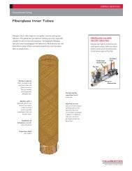
Swellpacker Technology<br />
The Swellpacker isolation system employs standard oilfield<br />
tubulars with rubber layers chemically bonded along their<br />
length. The rubber element swells upon exposure to<br />
hydrocarbons to form an effective annular seal through a<br />
process known as diffusion, which occurs as hydrocarbon<br />
molecules are absorbed by the rubber molecules and cause<br />
4
them to stretch. The oil enters the rubber, which swells the<br />
packer and ensures that it will rema<strong>in</strong> swollen, unlike water<br />
swell<strong>in</strong>g systems which can shr<strong>in</strong>k due to the effect of the<br />
osmosis process be<strong>in</strong>g reversible. Mere trace amounts of<br />
hydrocarbons are sufficient to <strong>in</strong>itiate the thermodynamic<br />
absorption process.<br />
The wellbore fluid’s viscosity and temperature are key<br />
variables <strong>in</strong> determ<strong>in</strong><strong>in</strong>g the time required for the<br />
Swellpacker system to absorb hydrocarbon and ultimately to<br />
set. Swell<strong>in</strong>g of the packer is consistent along its length.<br />
Although hydrocarbons will not degrade the rubber, they<br />
will alter its mechanical properties, such as hardness and<br />
tensile strength, depend<strong>in</strong>g on the rubber’s volume <strong>in</strong>crease.<br />
Swellpacker elements are chemically bonded to a tub<strong>in</strong>g or<br />
cas<strong>in</strong>g jo<strong>in</strong>t with element lengths tailored to accommodate<br />
the desired differential pressure. Slip-on sleeve designs are<br />
also available, normally <strong>in</strong> 12-<strong>in</strong> and 3-ft lengths, but for<br />
low-pressure applications.<br />
Thousands of Swellpacker systems have been run <strong>in</strong><br />
numerous wells worldwide for a variety of applications,<br />
<strong>in</strong>clud<strong>in</strong>g zonal isolation across the reservoir as a substitute<br />
for cement and provid<strong>in</strong>g backup should the l<strong>in</strong>er<br />
cementation prove unsuccessful.<br />
This <strong>Halliburton</strong> white paper is a summary of SPE 100361<br />
“PDO’s Proactive Approach to Solv<strong>in</strong>g a <strong>Zonal</strong> Isolation<br />
Challenge <strong>in</strong> Harweel HP Wells Us<strong>in</strong>g Swell Packers” by M.S.<br />
Laws, J.E. Fraser, and H.F. Soek, Petroleum Development<br />
Oman, and N. Carter, Easywell (now with Sensornet Ltd.);<br />
paper presented at the 2006 IADC/SPE Asia Pacific Drill<strong>in</strong>g<br />
Technology Conference and Exhibition, Bangkok, Thailand,<br />
13–15 November.<br />
Sales of <strong>Halliburton</strong> products and services will be <strong>in</strong> accord solely<br />
with the terms and conditions conta<strong>in</strong>ed <strong>in</strong> the contract between<br />
<strong>Halliburton</strong> and the customer that is applicable to the sale.<br />
Biblio # 10/07<br />
© 2007 <strong>Halliburton</strong>. All Rights Reserved.<br />
HALLIBURTON<br />
www.halliburton.com/redtech