
Create successful ePaper yourself
Turn your PDF publications into a flip-book with our unique Google optimized e-Paper software.
VALVES • VESSELS • SYSTEMS • CONTROLS<br />
700XH SERIES<br />
HIGH-SIDE PILOT-OPERATED VALVE<br />
BULLETIN 700H-SB13-01<br />
SERVICE BULLETIN<br />
System drawings shown in this bulletin are for illustration purposes only. Refrigeration systems should only be serviced by a qualified technician.<br />
Always observe proper safety procedures when servicing a refrigeration system. For more information see the latest revision of <strong>Phillips</strong> Safety<br />
Bulletin SGRV.<br />
GENERAL INFORMATION<br />
Pressure Rating:<br />
300 psig (21 bar, gauge)<br />
Temperature Rating: -20°F to 240°F<br />
(-29°C to 116°C)<br />
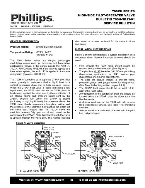
The 700H Series valves are flanged piston-type<br />
modulating valves used for ammonia and halocarbon<br />
applications. Valves in this series include the 700JRH,<br />
700XH, 700AXH and 700BXH. If the valve is applied to a<br />
halocarbon system, the suffix “F” is applied to the valve<br />
designation (example: 700JRHF).<br />
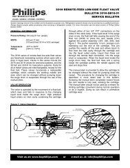
The 700H is controlled by a separate 275AP pilot float<br />
valve, typically to maintain a desired liquid level in a<br />
vertical condenser drain line or high pressure vessel.<br />
When the 275AP float valve is open (indicating a low<br />
liquid level), the PTFE seat disc on the 700H piston is<br />
held closed against the valve seat by the combination of<br />
an internal spring and pressure signal sent by the<br />
275AP. (Figure 1A) When the 275AP is closed<br />
(indicating a high liquid level) the pressure above the<br />
700H piston bleeds downstream through an orifice, and<br />
the pressure of the upstream flow pushes the piston off<br />
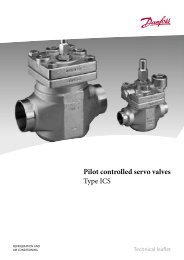
the valve seat. (Figure 1B) The 700XH valve will<br />
modulate between fully open and closed, based on the<br />
condition of the 275AP. Note that flow through the valve<br />
is upward, through the valve port. The manual opening<br />
stem must be screwed outward for the valve to close<br />
completely.<br />
INSTALLATION INSTRUCTIONS<br />
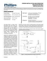
Figure 2 shows schematically a typical installation on a<br />
condenser drain. Several important features should be<br />
noted.<br />
Flow through the 700H valve should always be<br />
upward through the valve port. (See Figure 4)<br />
The pilot line MUST be either 3/8” OD copper tubing<br />
(halocarbon applications) or 1/4” nominal pipe<br />
(halocarbon or ammonia applications).<br />
The pilot line should include a shut-off valve,<br />
pressure gauge and gauge valve for diagnostics.<br />
(See Troubleshooting section, pages 3 & 4)<br />
The 275AP float valve should be at least 18 in.<br />
above the 700H valve.<br />
Any reduction in the condenser drain line should be<br />
located below the 275AP, after the elbow turns the<br />
flow horizontal.<br />
A strainer upstream of the 700H will help ensure<br />
long, dependable service. See Table 1 for matching<br />
strainers.<br />
Always install in a horizontal pipe line with the pilot<br />
line port pointing up.<br />
Figure 1: Valve Operation<br />
PILOT FLOW<br />
FROM 275AP<br />
SPRING<br />
PISTON<br />
PISTON ORIFICE<br />
VALVE SEAT<br />
VALVE PORT<br />
A: VALVE CLOSED B: VALVE OPEN<br />
700H-SB13-01 1<br />
Visit us at: www.haphillips.com or e-mail us at: info@haphillips.com
18"<br />
Recommended<br />
<strong>Co</strong>ndenser<br />
Drain<br />
Figure 2: Typical Installation<br />
275AP<br />
1 4 " Nom. Pipe<br />
or 3 8" Tubing<br />
700H with<br />
Optional<br />
Strainer<br />
Pressure<br />
Gauge<br />
To Lower Pressure<br />
Vessel<br />
Manual Bypass<br />
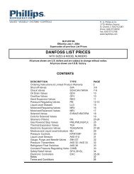
Figure 3: Replacement Parts and Dimensions<br />
C<br />
16<br />
15<br />
1<br />
E<br />
D<br />
A B C D E F<br />
700JRH 4.2 4.5 4.4 3.5 3.5 4.5<br />
700XH 4.2 4.5 5.0 4.0 3.8 4.5<br />
700AXH 5.4 5.3 4.8 8.8 9.8 7.8<br />
700BXH 6.9 6.9 6.0 10.0 12.3 10.0<br />
17<br />
6<br />
2<br />
1 4 " NPT<br />
4<br />
3<br />
7<br />
A<br />
10<br />
5<br />
F<br />
14<br />
12<br />
13<br />
9<br />
11<br />
8<br />
B<br />
700H-SB13-01 2
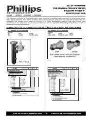
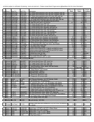
REPLACEMENT PARTS<br />
When contacting <strong>Phillips</strong> for replacement parts, have the complete valve model and serial number (shown on the valve<br />
nameplate) available to ensure you receive the correct components. For example: “700JRHF-ZEDDA” is a complete<br />
valve model, and “990123” or “E-12345” are complete serial numbers.<br />
Table 1: Replacement Parts<br />
Item<br />
#<br />
Description 700JRH 700XH 700AXH 700BXH<br />
1 Bonnet Screw 577 (4) 577 (4) 718 (4) 1459 (4)<br />
2 Bonnet 702JRS 702S 702AS 702BS<br />
3 Bonnet Gasket* 710 710 710A 710B<br />
4 Spring See Valves & Accessories Book – High Side <strong>Co</strong>ntrols Section or <strong>Co</strong>nsult Factory<br />
5 Piston 700-4JRH 700-4XH 700-4AXH 700-4BXH<br />
6 Valve Body 700JRF-VB 700F-VB 700AF-VB 700BXF-VB<br />
7 Flange Gasket* 506 (2) 725N (2) 73 (2) 326Y (2)<br />
8 Seat Disc* 703 700-3X 700-3AX 700-3BX<br />
9 Metering Plug <strong>Co</strong>nsult Factory<br />
10 Manual Stem 711XS 711XS 711X 711B<br />
11 Packing Ring 775 775 775 777BN<br />
12 Gland 8 8 8 8B<br />
13 Seal Cap 714 714 714 714B<br />
14 Seal Cap Gasket 720 720 720 720B<br />
15 Flange Bolt<br />
Valve without<br />
Strainer:<br />
726B (2)<br />
Valve without<br />
Strainer:<br />
726 (2)<br />
Valve without<br />
Strainer:<br />
23 (8)<br />
Valve without<br />
Strainer:<br />
24A (8)<br />
Valve with Strainer: Valve with Strainer: Valve with Strainer: Valve with Strainer:<br />
726D (2)<br />
Valve without<br />
Strainer:<br />
58 (2)<br />
726E (2)<br />
Valve without<br />
Strainer:<br />
58 (2)<br />
23 (12)<br />
Valve without<br />
Strainer:<br />
58 (8)<br />
24A (12)<br />
Valve without<br />
Strainer:<br />
59 (8)<br />
16 Flange Nut<br />
Valve with Strainer: Valve with Strainer: Valve with Strainer: Valve with Strainer:<br />
58 (2)<br />
58 (2)<br />
58 (12)<br />
59 (12)<br />
- Strainer S701JRP S701 S701A S701B<br />
Strainer Kit<br />
17 (Includes Filter<br />
S701JR-SA S701-SA S701A-SA S701B-SA<br />
Element & Gasket)<br />
-<br />
*Spare Parts Kit<br />
(Includes Items 3, 7, 8)<br />
SERVICE INSTRUCTIONS<br />
K700JR K700X K700AX K700BX<br />
The metering plug is threaded tightly into the piston and secured with thread locking compound. Be careful not to<br />
damage the piston surface when replacing a metering plug. Always use thread locking compound when installing the<br />
replacement plug.<br />
TROUBLESHOOTING<br />
Always be sure flow through the valve is in the proper<br />
direction. An arrow is affixed to each valve at the time it is<br />
manufactured. This arrow may not be visible in all<br />
installations. To ensure the 700H is installed properly,<br />
note the following. When facing the side of the valve<br />
bearing the name ”PHILLIPS” (Figure 4), flow should be<br />
From right-to-left for 700JRH, 700XH, 700AXH<br />
valves<br />
From left-to-right for 700BXH valves<br />
Valve Chatters: Chattering or vibration can be<br />
caused by an over-sized metering plug opening and<br />
closing rapidly in an attempt to satisfy a low<br />
refrigeration load. <strong>Co</strong>nsider using a smaller capacity<br />
plug.<br />
Broken Spring: A broken spring in a 700H valve<br />
that is less than a few years old can also indicate<br />
an over-sized metering plug. <strong>Co</strong>ntinual, rapid<br />
opening and closing to satisfy a small load will<br />
fatigue the spring. When replacing the spring, also<br />
consider replacing the metering plug with one<br />
having a smaller capacity.<br />
700H-SB13-01 3
<strong>Co</strong>ndenser Liquid Level is:<br />
TROUBLESHOOTING (<strong>Co</strong>ntinued)<br />
Figure 4: Direction of Flow<br />
Many problems with the operation of the<br />
pilot-operated 700H should be diagnosed in<br />
conjunction with the 275AP pilot. Figure 2<br />
shows schematically how these valves<br />
operate together.<br />
As the liquid level rises in the 275AP float<br />
chamber, the float ball rises and an internal<br />
needle shuts off flow to the top of the 700H.<br />
The pressure above the 700H piston drops<br />
and the piston rises due to higher pressure<br />
underneath, opening the valve port and<br />
allowing flow. <strong>Co</strong>nversely, as the liquid level<br />
drops, the 275AP opens and pressure<br />
above the piston rises, closing the 700H port<br />
with spring assist.<br />
FLOW DIRECTION FOR<br />
700JRH, 700XH,<br />
700AXH<br />
700BXH<br />
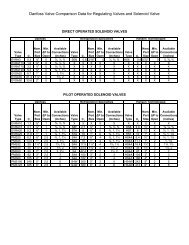
A pressure gauge in the pilot line is required<br />
to diagnose operating problems. To identify<br />
the cause of a problem, match the liquid<br />
condition (high or low) with the pressure gauge reading (condensing or downstream pressure) and note the possible<br />
causes given in Table 2.<br />
Table 2: Troubleshooting the 275AP & 700H<br />
T<br />
o<br />
o<br />
h<br />
i<br />
g<br />
h<br />
Approximately Downstream Pressure<br />
The pressure indicates that the 275AP is closed (as it<br />
should be). Therefore the 700H may be closed due to a<br />
malfunction.<br />
Check if the 700H is stuck partially or completely closed by<br />
dirt/debris, or if the strainer is blocked.<br />
Other possibilities: Operating conditions may have changed<br />
so that (1) The 700H cannot open fully due to too-strong<br />
spring, or (2) the 700H metering plug does not have<br />
sufficient capacity. <strong>Co</strong>ntact <strong>Phillips</strong> to resolve these issues.<br />
Pressure Gauge reads:<br />
Approximately <strong>Co</strong>ndensing Pressure<br />
The pressure indicates the 275AP is open (it is supposed to<br />
be closed). Therefore the 700H is being signaled to close<br />
inappropriately.<br />
Check if 275AP float is stuck in low (open) position, or if<br />
dirt/debris is keeping the needle from seating. See 275AP<br />
Service Bulletin to resolve the problem.<br />
Other possibilities: The 700H is installed backward. See<br />
Figure 4.<br />
T<br />
o<br />
o<br />
l<br />
o<br />
w<br />
The pressure indicates the 275AP is closed (it is supposed<br />
to be open). Therefore the 700H is being signaled to open<br />
inappropriately.<br />
Check if the 275AP is stuck in the closed position. See<br />
275AP Service Bulletin to resolve the problem.<br />
The pressure level indicates the 275AP is open (as it should<br />
be). Therefore the 700H is open due to malfunction.<br />
Check if the 700H is stuck partially or completely open by<br />
dirt/debris, or the spring may have broken.<br />
Other possibilities: (1) The manual opening stem is partly<br />
screwed inward. (2) The 700H piston or body may have<br />
worn, permitting blow-by that prevents the pressure above<br />
piston from rising sufficiently to close the valve. (3)<br />
Operating conditions may have changed so that the 275AP<br />
does not have sufficient capacity to close the 700H. <strong>Co</strong>ntact<br />
<strong>Phillips</strong> to resolve these issues.<br />
H. A. <strong>Phillips</strong> & <strong>Co</strong>.<br />
770 Enterprise Avenue<br />
DeKalb, IL 60115 U.S.A.<br />
Phone: (630) 377-0050<br />
Fax: (630) 377-2706<br />
Remit to:<br />
Department 20-8043<br />
P. O. Box 5998<br />
Carol Stream, IL 60197-5998<br />
700H-SB13-01 4