SERVICE BULLETIN - HA Phillips & Co.
SERVICE BULLETIN - HA Phillips & Co.
SERVICE BULLETIN - HA Phillips & Co.

Create successful ePaper yourself
Turn your PDF publications into a flip-book with our unique Google optimized e-Paper software.
VALVES • VESSELS • SYSTEMS • CONTROLS<br />
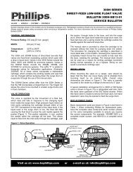
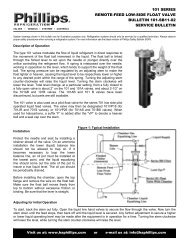
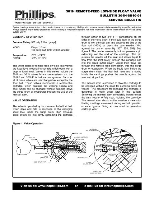
301H REMOTE-FEED LOW-SIDE FLOAT VALVE<br />
<strong>BULLETIN</strong> 301H-SB10-01<br />
<strong>SERVICE</strong> <strong>BULLETIN</strong><br />
System drawings shown in this bulletin are for illustration purposes only. Refrigeration systems should only be serviced by a qualified technician.<br />
Always observe proper safety procedures when servicing a refrigeration system. For more information see the latest revision of <strong>Phillips</strong> Safety<br />
Bulletin SGRV.<br />
GENERAL INFORMATION<br />
Pressure Rating: 300 psig [21 bar, gauge]<br />
MOPD:<br />
Temperature -20ºF to 240ºF<br />
Rating: [-29ºC to 116ºC]<br />
250 psi [17 bar]<br />
(120 psi [8 bar] 301H w/ 9/32 cartridge)<br />
The 301H series of remote-feed low-side float valves<br />
are fixed-level modulating controls which open with a<br />
drop in liquid level. Valves in this series include the<br />
301A and 301H valves for ammonia systems, and the<br />
301AF and 301HF for halocarbon systems. Parts for<br />
all of these valves are interchangeable, except for the<br />
float ball. These valves incorporate a replaceable<br />
cartridge, which contains the working needle and<br />
seat, which can be changed without pumping down<br />
the surge drum or evaporator through the use of the<br />
manual stem.<br />
VALVE OPERATION<br />
The valve is operated by the movement of a float ball,<br />
which rises and falls in response to the changing<br />
liquid level inside the surge drum. High pressure<br />
liquid enters an inlet cavity containing the cartridge<br />
through either of two 3/4” FPT connections on the<br />
sides of the valve body. If the liquid level in the surge<br />
drum is low, the float ball falls causing the end of the<br />
float rod (343H) to press the cam needle (314)<br />
against the pusher assembly (357, 358, 359). See<br />
figure 1. The pusher assembly, in turn, presses a pin<br />
extending out the end of the cartridge. This pin<br />
pushes the needle off the seat and allows liquid to<br />
flow from the inlet cavity through the cartridge and<br />
into the liquid outlet cavity. Liquid then flows out<br />
through the remote feed connection, into the surge<br />
drum or evaporator. When the liquid level inside the<br />
surge drum rises, the float ball rises and a spring<br />
inside the cartridge pushes the needle against the<br />
seat and stops flow.<br />
The manual stem is provided to allow the cartridge to<br />
be changed without the need for pumping down the<br />
vessel. The procedure for changing the cartridge is<br />
described in more detail later in this bulletin.<br />
Screwing the manual stem completely inward forces<br />
the cam needle to fully seat, isolating the cartridge.<br />
The manual stem should not be used as a means for<br />
limiting cartridge movement during normal operation<br />
or as a bypass. Doing so can result in premature<br />
cartridge wear.<br />
Figure 1: Valve Operation<br />
PIN EXTENDS<br />
OUT OF CARTRIDGE<br />
FLOAT<br />
FLOAT ROD<br />
(343H)<br />
MANUAL STEM<br />
LIQUID INLET CAVITY<br />
CARTRIDGE<br />
CAM NEEDLE (314)<br />
PUSHER<br />
(357, 358, 359)<br />
CAM NEEDLE (314)<br />
LIQUID OUTLET<br />
CAVITY<br />
LIQUID OUTLET CAVITY<br />
PUSHER<br />
(357, 358, 359)<br />
NEEDLE & SEAT<br />
(INSIDE CARTRIDGE)<br />
Visit us at: www.haphillips.com or e-mail us at: info@haphillips.com<br />
301H-SB11-01 1
INSTALLATION<br />
When mounting the valve on a vessel, care should be taken that the float can move freely and is shielded from<br />
incoming liquid by an internal baffle. Overall valve dimensions are shown in figure 2. The valve is typically mounted<br />
to the vessel by a flange on the end of a 3” pipe.<br />
Figure 2: Valve Dimensions<br />
0.8 [19]<br />
1.8 [44]<br />
3" SOCKET WELD<br />
CONNECTION<br />
3" FPT<br />
CONNECTION<br />
3/4" FPT LIQUID INLET<br />
EITHER SIDE OF BODY<br />
2.4 [60]<br />
12.3 [312] (301H)<br />
14.8 [375] (301A)<br />
BAFFLE SHIELDS FLOAT FROM<br />
FALLING LIQUID<br />
5.3 [135]<br />
MANUAL STEM<br />
3.0 [76]<br />
3.8 [95] (301H)<br />
4.0 [102] (301A)<br />
2.8 [71] (301H)<br />
3.3 [83] 301A<br />
7.5 [189] (301H)<br />
10.0 [254] (301A)<br />
13 [330] (301H)<br />
15.5 [394] (301A)<br />
KEEP AREA FREE OF OBSTRUCTIONS<br />
4.3 [108] MAX<br />
PIPE LENGTH<br />
45°<br />
3 4" FPT REMOTE<br />
FEED OUTLET<br />
Ø5.5 [Ø140]<br />
(6) 0.5 [13] HOLES ON<br />
Ø4.5 [114] B.C<br />
FOR 7/16-20 UNF<br />
A typical installation arrangement is shown in<br />
figure 3. Notice the optional shutoff solenoid in<br />
the liquid supply line. When the refrigeration<br />
load is greatly reduced on an individual air unit,<br />
or if fans are shut off, it is advisable to close<br />
the liquid line solenoid ahead of the float valve<br />
in order to stop liquid feed. Otherwise the body<br />
of liquid in the surge drum will flow down into<br />
the coil and the float valve will continue<br />
feeding, thus filling the coil with liquid<br />
refrigerant. Room thermostats can be used to<br />
stop liquid feed to the evaporators.<br />
Figure 3: Typical Installation<br />
GAS<br />
RETURN<br />
SURGE<br />
DRUM<br />
SUCTION<br />
3 4 " LIQUID SUPPLY<br />
SHUT-OFF<br />
SOLENOID<br />
VALVE<br />
<strong>HA</strong>ND<br />
EXPANSION<br />
VALVE<br />
LIQUID<br />
TO COIL<br />
301H SERIES<br />
FLOAT VALVE<br />
500 SERIES<br />
STRAINER<br />
OIL DRAIN<br />
301H-SB11-01 2
REPLACEMENT PARTS<br />
Basic replacement parts are shown in figure 4. When contacting <strong>Phillips</strong> for replacement parts, have the complete<br />
valve model and serial number (shown on the valve nameplate) available to ensure you receive the correct<br />
components. For example: 301HF-NZZ is a complete model number, and 990105 is a complete serial number.<br />
Figure 4: Replacement Parts<br />
20<br />
11<br />
1<br />
18<br />
12, 13, 14<br />
10<br />
27<br />
2<br />
16<br />
26<br />
21<br />
22<br />
8<br />
23<br />
9<br />
6<br />
3<br />
15<br />
19<br />
17<br />
7<br />
4<br />
5<br />
24, 25<br />
Table 1: Replacement Parts<br />
301H<br />
301A<br />
1 Valve Body 301-VB 301-VB<br />
2 Cartridge* 355 355<br />
3 Pusher* 358 358<br />
4 Gasket* 365 365<br />
5 Access Plug 363 363<br />
6 Boss 307B 307B<br />
7 Gasket 326 326<br />
8 Gland 8 8<br />
9 Cam Needle 314 314<br />
10 Float Block 315R 315R<br />
11 Lever Pin 11 11<br />
12 Adjusting Screw 369A 369A<br />
13 Nut 324 324<br />
14 Lock Washer 55 55<br />
15 Nut 88 88<br />
16 Lock Washer (2) 55A 55A<br />
17 Nut 87 87<br />
18 Pipe Plug 90P 90P<br />
19 Float Rod 343H 343H<br />
20<br />
Float Ball (Ammonia) 370M 370A<br />
Float Ball (Halocarbon) 370MF 370AF<br />
21 Retainer 776 776<br />
22 Packing Ring 775 775<br />
23 Stem 377 377<br />
24 Hex Nut 359 359<br />
25 Hex Head Screw 357 357<br />
26 Hex Head Cap Screws (6) 325 325<br />
27 Spacers 11S 11S<br />
Spare Parts Kit<br />
(Includes items 2, 3 & 4)<br />
Specify orifice diameter when ordering<br />
K355<br />
K355<br />
<strong>SERVICE</strong> INSTRUCTIONS<br />
Refrigeration systems should only be<br />
serviced by a qualified technician. Always<br />
observe proper safety procedures.<br />
Changing the Cartridge (Needle &<br />
Seat)<br />
When wear of the needle and seat<br />
justifies replacement, it is<br />
recommended that a completely new<br />
cartridge be obtained. These are<br />
assembled and tested at the factory<br />
for pressure tightness. Cartridge<br />
removal for replacement or cleaning<br />
is accomplished as follows.<br />
1. Shut off the hand valve in the<br />
liquid line and let the compressor<br />
run until the liquid line is<br />
completely empty. If the<br />
evaporator has been flooding<br />
badly, pump it down until the<br />
liquid level is below the float<br />
valve.<br />
(<strong>Co</strong>ntinued on next page)<br />
301H-SB11-01 3
2. Turn the float valve manual stem into the<br />
valve until firm. DO NOT USE A HEAVY<br />
WRENCH. The manual stem bears against<br />
the float block and seats the cam needle. This<br />
isolates the cartridge chamber without<br />
requiring a full pump down of the vessel.<br />
3. Close the hand valve in the remote feed line.<br />
4. Unscrew the access plug, venting refrigerant<br />
as necessary. Unscrew the cartridge by<br />
grasping it by the square shank (figure 5).<br />
5. The pusher assembly is now accessible for<br />
inspection and replacement if it shows signs<br />
of wear on the sliding surfaces. The pusher<br />
assembly should slide freely on the boss.<br />
Figure 5: Cartridge Removal<br />
Figure 6: Pusher Adjustment<br />
314<br />
CORRECT<br />
307B<br />
359<br />
358 357<br />
3/32" CAM<br />
NEEDLE<br />
MOVEMENT<br />
PROPERLY ADJUSTED<br />
PUSHER<br />
ADJUST<br />
AS REQ'D<br />
Figure 7: Rod Movement<br />
INSUFFICIENT<br />
MOVEMENT<br />
TOO<br />
SMALL<br />
IMPROPERLY ADJUSTED<br />
PUSHER CANNOT FULLY<br />
OPEN CARTRIDGE<br />
INCORRECT<br />
TOO MUCH<br />
MOVEMENT<br />
TOO<br />
LARGE<br />
IMPROPERLY ADJUSTED<br />
PUSHER CANNOT FULLY<br />
SEAT CAM NEEDLE<br />
343H<br />
355 CARTRIDGE<br />
APPROXIMATELY 5°<br />
APPROXMATELY 5°<br />
USE SQUARE S<strong>HA</strong>NK<br />
TO UNSCREW CARTRIDGE<br />
FROM BODY<br />
CARTRIDGE SIZE<br />
STAMPED ON<br />
HEX PLUG<br />
87, 55A<br />
365 GASKET<br />
363 PLUG<br />
6. If the pusher assembly must be replaced,<br />
carefully note the adjustment of the old pusher<br />
to ensure proper needle movement after<br />
reassembly (figure 6). The overall length of<br />
the pusher should be about 1.30” (33 mm).<br />
This should provide about 3/32” (2 mm)<br />
cartridge movement after reassembly.<br />
7. Install new parts in the valve, and tighten the<br />
new cartridge firmly. Replace the access plug<br />
using a new gasket.<br />
8. Back the manual stem out fully. The valve is<br />
now ready to be put back in service.<br />
Replacing parts other than the Cartridge and<br />
Pusher<br />
To replace parts other than the cartridge and<br />
pusher, the evaporator must be fully evacuated<br />
and the valve removed from the vessel. Figure 7<br />
shows proper movement of float rod when the rod<br />
is correctly threaded into the float block and<br />
locknut (87, 55A) is tightened.<br />
TROUBLESHOOTING<br />
Problem: Valve overfeeds, flooding the vessel.<br />
Causes/Solutions:<br />
• Cartridge worn, will not shut off properly. Replace<br />
cartridge.<br />
• Pusher assembly worn/jammed, will not allow cartridge<br />
to close. Replace pusher assembly.<br />
• Float ball developed leak, will not allow float rod to rise.<br />
<strong>Co</strong>nfirm leak by immersing ball in warm water and<br />
observing bubbles. Replace float ball.<br />
Problem: Valve underfeeds, starving the vessel.<br />
Causes/Solutions:<br />
• Pusher assembly worn/jammed, will not allow cartridge<br />
to open. Replace pusher assembly.<br />
Problem: Back-seating arrangement does not operate<br />
correctly.<br />
Causes/Solutions:<br />
• Parts worn or out of adjustment. Vessel must be<br />
pumped down for servicing. With manual stem backedout<br />
1/4-turn from full inward, adjusting screw (369A)<br />
should cause cam needle to fully seat. Fully backed-out<br />
manual stem should allow float to rise and close<br />
cartridge.<br />
H. A. <strong>Phillips</strong> & <strong>Co</strong>.<br />
770 Enterprise Avenue<br />
DeKalb, IL 60115 U.S.A.<br />
Phone: (630) 377-0050<br />
Fax: (630) 377-2706<br />
Remit to:<br />
Department 20-8043<br />
P. O. Box 5998<br />
Carol Stream, IL 60197-5998<br />
301H-SB11-01 4