screamin' eagle 64mm pro high flow efi throttle ... - Harley-Davidson
screamin' eagle 64mm pro high flow efi throttle ... - Harley-Davidson
screamin' eagle 64mm pro high flow efi throttle ... - Harley-Davidson

Create successful ePaper yourself
Turn your PDF publications into a flip-book with our unique Google optimized e-Paper software.
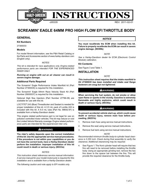
-J05335 REV. 2011-02-01<br />
SCREAMIN' EAGLE 64MM PRO HIGH FLOW EFI THROTTLE BODY<br />
GENERAL<br />
Kit Numbers<br />
27300033<br />
Models<br />
For model fitment information, see the P&A Retail Catalog or<br />
the Parts and Accessories section of www.harley-davidson.com<br />
(English only).<br />
NOTES<br />
This kit is intended for race applications only. Engine-related<br />
performance parts are intended FOR THE EXPERIENCED<br />
RIDER ONLY.<br />
Running an engine with out an air cleaner can result in<br />
severe engine damage.<br />
Additional Parts Required<br />
The Screamin' Eagle Performance Intake Manifold kit (Part<br />
Number 27300035) is required for this installation.<br />
The Screamin' Eagle <strong>64mm</strong> Race Velocity Stack Kit (Part<br />
Number 29000037) is required for this installation.<br />
Optional High <strong>flow</strong> Injectors (Part Number 27796-08) are<br />
available for use with this kit.<br />
LOCTITE ® 243 (Blue) Threadlocker and Sealant is needed for<br />
<strong>pro</strong>per installation of this kit. A 0.5 mL pack of Loctite 243 is<br />
included with this kit. A 6.0 mL tube (Part No. 99642-97) is<br />
available from a <strong>Harley</strong>-<strong>Davidson</strong> dealer.<br />
This engine related performance part is not legal for use on<br />
pollution controlled motor vehicles. This kit may reduce or void<br />
the Limited Vehicle Warranty coverage. Engine related performance<br />
parts are intended for the experienced rider only.<br />
The rider's safety depends upon the correct installation<br />
of this kit. Use the ap<strong>pro</strong>priate service manual <strong>pro</strong>cedures.<br />
If the <strong>pro</strong>cedure is not within your capabilities or you do<br />
not have the correct tools, have a <strong>Harley</strong>-<strong>Davidson</strong> dealer<br />
perform the installation. Im<strong>pro</strong>per installation of this kit<br />
could result in death or serious injury. (00333a)<br />
NOTES<br />
This instruction sheet references service manual information.<br />
A service manual for your model motorcycle is required for this<br />
installation and is available from a <strong>Harley</strong>-<strong>Davidson</strong> dealer.<br />
The following caution and note apply to EFI models only.<br />
You must recalibrate the ECM when installing this kit.<br />
Failure to <strong>pro</strong>perly recalibrate the ECM can result in severe<br />
engine damage. (00399b)<br />
NOTE<br />
See a <strong>Harley</strong>-<strong>Davidson</strong> dealer for ECM (Electronic Control<br />
Module) calibration.<br />
Kit Contents<br />
See Figure 3 and Table 1.<br />
INSTALLATION<br />
NOTE<br />
This instruction sheet requires that the intake manifold in<br />
Kit 27300035 has been installed and intake seal flange<br />
fasteners are snug but not tightened.<br />
When servicing the fuel system, do not smoke or allow<br />
open flame or sparks in the vicinity. Gasoline is extremely<br />
flammable and <strong>high</strong>ly explosive, which could result in<br />
death or serious injury. (00330a)<br />
To prevent accidental vehicle start-up, which could cause<br />
death or serious injury, remove main fuse before <strong>pro</strong>ceeding.<br />
(00251b)<br />
1. Remove main fuse using service manual instructions.<br />
2. Remove the seat using service manual instructions.<br />
3. Remove fuel tank using service manual instructions.<br />
NOTE<br />
Recommended minimum <strong>throttle</strong> body-to-cylinder head clearance<br />
is 0.250 inch. Check during final assembly to verify the<br />
clearance. Additional clearancing may be required.<br />
4. See Figure 1. The front cylinder head will require that two<br />
fins will need to be removed before installing the <strong>throttle</strong><br />
body. Using an ap<strong>pro</strong>priate grinding tool, remove the two<br />
fins down to the spacer bar between the fins. This will<br />
<strong>pro</strong>vide the required clearance for the <strong>throttle</strong> body.<br />
-J05335 1 of 3
is06927<br />
7. Install the O-rings (D) in the grooves around the velocity<br />
stack breather screw plugs (C). Lightly lubricate the O-<br />
rings with engine oil or white lithium grease.<br />
2<br />
1<br />
8. Install the breather screw plugs (C) with the O-rings to the<br />
velocity stack backplate.<br />
9. Alternately tighten the intake manifold seal flange screws<br />
to 96-144 in-lbs (10.9-16.3 Nm).<br />
10. Install connectors to fuel injectors.<br />
is06928<br />
1. Cylinder fins<br />
2. Spacer bar<br />
1<br />
Figure 1. Remove Fin Material for Throttle Body Clearance<br />
When servicing the fuel system, do not smoke or allow<br />
open flame or sparks in the vicinity. Gasoline is extremely<br />
flammable and <strong>high</strong>ly explosive, which could result in<br />
death or serious injury. (00330a)<br />
Throttle Body Installation<br />
1. See Figure 3 and Table 1. Install Throttle Control Actuator<br />
conversion (TCA) harness (2) to <strong>throttle</strong> body and TCA<br />
connector on vehicle. Push to close the yellow locking tab<br />
on TCA harness. This will make sure the connector is<br />
locked to the <strong>throttle</strong> body.<br />
2. Remove the backing from the adhesive side of the backplate<br />
gasket (E). Carefully align the holes, and install the<br />
gasket on the <strong>throttle</strong> body side of the backplate.<br />
3. Apply a small amount of Loctite to the <strong>throttle</strong> body screw<br />
(F) threads. Use the four screws (F) to fasten the <strong>throttle</strong><br />
body (1) to the velocity stack (A) backplate. Tighten the<br />
screws to 55-60 in-lbs (6.2-6.8 Nm).<br />
4. Assemble the velocity stack and intake tube (A) to the<br />
backplate using the instruction sheet.<br />
5. Insert the breather screws (B) through the backplate on<br />
the velocity stack (A). Install the new O-rings in the<br />
grooves around the breather screw holes on induction<br />
module side of the backplate.<br />
6. Apply a small amount of Loctite to the breather screw (B)<br />
threads and the mating tapped holes in the cylinder head.<br />
Install the velocity stack/<strong>throttle</strong> body subassembly to the<br />
cylinder heads/intake manifold and thread in the screws<br />
(B). Alternately tighten the screws to 120-144 in-lbs (13.6-<br />
16.3 Nm).<br />
1. Throttle body harness<br />
Figure 2.Tie Excess Throttle Body Harness Out of the Way<br />
11. See Figure 2. It is recommended to wrap the conversion<br />
harness lead around the bottom of the <strong>throttle</strong> body and<br />
ty-rap the harness securely. In all cases, to avoid chafing<br />
or other damage to the harnesses make sure:<br />
• Slack is allowed at cylinder heads for relative motion.<br />
• Extra wire harness leads should be cinched up as needed<br />
to keep from rubbing on cylinder, head fins, frame, etc.<br />
12. Refer to the service manual and install the fuel tank.<br />
13. Refer to the service manual and install the main fuse.<br />
After installing seat, pull upward on seat to be sure it is<br />
locked in position. While riding, a loose seat can shift<br />
causing loss of control, which could result in death or<br />
serious injury. (00070b)<br />
14. Install the seat using service manual instructions.<br />
-J05335 2 of 3
SERVICE PARTS<br />
is06926<br />
F<br />
1<br />
G<br />
E<br />
2<br />
B<br />
A<br />
C<br />
D<br />
Figure 3. Service Parts: Screamin' Eagle <strong>64mm</strong> Pro High Flow EFI Throttle Body<br />
Table 1. Service Parts Table<br />
Item<br />
Description (Quantity)<br />
1 ETC, EFI, Throttle body, <strong>64mm</strong><br />
2 Wire harness, ETC conversion<br />
Items mentioned in text, but not included in kit:<br />
A Velocity stack<br />
B Breather screw (2)<br />
C Plug (2)<br />
D O-ring, #6-021 (4)<br />
E Gasket, <strong>throttle</strong> body<br />
F Screw, TORX ® socket head 1/4-20 x 2 inch (4)<br />
G Intake manifold<br />
Part Number<br />
Not Sold Separately<br />
69200251<br />
-J05335 3 of 3