Chapter 6
Chapter 6
Chapter 6

You also want an ePaper? Increase the reach of your titles
YUMPU automatically turns print PDFs into web optimized ePapers that Google loves.
EE 201 ELECTRIC CIRCUITS<br />
LECTURE 20<br />
The material covered in this lecture will be as follows:<br />
The Inductor.<br />
Current-Voltage Relations of Inductor.<br />
Power and Energy in the Inductor.<br />
At the end of this lecture you should be able to:<br />
<br />
<br />
<br />
<br />
<br />
Understand and apply the inductor’s current-voltage differential relation.<br />
Derive and apply the inductor’s current-voltage integral relation.<br />
Understand that zero inductor’s voltage implies D.C. inductor’s current and vice versa.<br />
Derive the inductor’s power and energy relations.<br />
Apply the inductor’s energy relation.<br />
Energy Storage Elements:<br />
Some electric circuit elements can store electric energy. These include the capacitor and the<br />
inductor.<br />
A resistor clearly is not an energy storage element, because the electric energy it absorbs is<br />
converted to heat energy and thus it is lost.<br />
Ideal voltage sources and ideal current sources are not considered energy storage elements.<br />
Energy storage elements (ESE) can absorb electric energy. This energy remains in electric form<br />
(stored).<br />
ESE can also deliver electric energy, but they can only deliver the energy that has been previously<br />
absorbed (stored energy).<br />
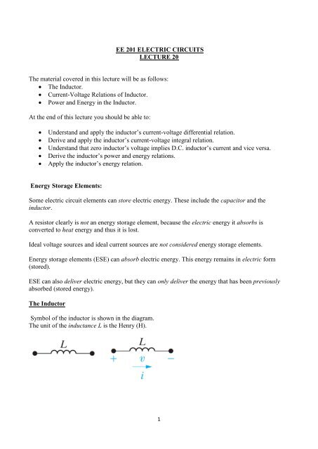
The Inductor<br />
Symbol of the inductor is shown in the diagram.<br />
The unit of the inductance L is the Henry (H).<br />
1
Current-Voltage Relationship in the Inductor:<br />
1- Differential Relation:<br />
The current-voltage relation in an inductor is:<br />
v L t = L di L(t)<br />
dt<br />
( eq.1)<br />
This differential relation is valid only if i L enters the (+) side of v L .<br />
A minus sign must be inserted in the above relation if i L enters the (-) side of v L [According to the<br />
passive sign convention].<br />
[The voltage across an inductor is proportional to the rate of change of the current through the<br />
inductor].<br />
Example 6.1<br />
The independent current source in the circuit generates zero current for t < 0 and a pulse of 10te -5t A<br />
for t > 0.<br />
i t =<br />
0 t < 0<br />
10te −5t A t > 0<br />
a) Sketch the current waveform.<br />
b) Express the voltage across the inductor as a function of time.<br />
c) Sketch the voltage waveform.<br />
v L t = L di L(t)<br />
dt<br />
di<br />
dt = 10e−5t + 10t(−5e −5t )<br />
di<br />
= (10 − 50t)e−5t<br />
dt<br />
v L t = (1 − 5t)e −5t V<br />
2
2- Integral Relation<br />
v L t = L di L(t)<br />
dt<br />
(eq. 2)<br />
v L dt = Ldi L (eq. 3)<br />
Integrate both sides<br />
i L t = 1 L<br />
t<br />
t 0<br />
v L d + i(t 0 )<br />
(eq.4)<br />
Example 6.2<br />
The voltage pulse applied to the 100 mH inductor shown in Figure is given by<br />
v t =<br />
0 t < 0<br />
20te −10t V t > 0<br />
Assume i = 0 for t ≤ 0.<br />
a) Sketch the voltage waveform.<br />
b) Express the inductor current as a function of time.<br />
c) Sketch the current waveform.<br />
3
i L t = 1<br />
0.1<br />
t<br />
0<br />
20e −10 d + i(0)<br />
i L t = 200<br />
−e −10<br />
100 (10 + 1) t 0<br />
= 2 − 20te −10t − 2e −10t A<br />
Power and Energy Relations in the Inductor:<br />
The instantaneous power p(t) absorbed by an inductor is given by:<br />
p t = v L t i L t<br />
p = Li di<br />
dt<br />
(eq.5)<br />
(eq.6)<br />
Or expressing the current in terms of the voltage<br />
p = v 1 L<br />
t<br />
t 0<br />
v d + i(t 0 )<br />
(eq.7)<br />
Also, power is the time rate of expending energy, so<br />
p = dw<br />
dt<br />
pdt = dw<br />
dw = pdt<br />
dw = Li di<br />
(eq.8)<br />
(eq.9)<br />
(eq.10)<br />
(eq.11)<br />
Integrate both sides<br />
w = 1 2 Li2<br />
(eq.12)<br />
4
Example 6.3<br />
The independent current source in the circuit generates zero current for t < 0 and a pulse of 10te -5t A<br />
for t > 0.<br />
i t =<br />
0 t < 0<br />
10te −5t A t > 0<br />
a) Derive the expressions for the inductor voltage, power, and energy.<br />
b) Sketch the current, voltage, power, and energy as functions of time.<br />
c) Specify the interval of time when energy is being stored in the inductor.<br />
d) Specify the interval of time when energy is being extracted from the inductor.<br />
e) Evaluate the integrals<br />
0.2<br />
p dt<br />
0<br />
and<br />
∞<br />
0.2<br />
p dt<br />
Solution<br />
a)<br />
v L t = (1 − 5t)e −5t V<br />
p t = vi = 10te −10 − 50t 2 e −10t W<br />
w t = 1 2 Li2 = 1 2 × 100 × 10−3 100t 2 e −10t<br />
b)<br />
= 5t 2 e −10t J<br />
5
c) Energy is being stored in the capacitor whenever the power is positive. In the interval (0, 0.2) s.<br />
d) Energy is being extracted whenever the power is negative. In the interval ( 0.2, ∞) s.<br />
e)<br />
0.2<br />
p dt<br />
0<br />
= 10 e−10t<br />
0.2<br />
100 −10t − 1 − 50 t2 e −10t<br />
−10 + 2<br />
10<br />
0<br />
e −10t<br />
100 −10t − 1 0<br />
0.2<br />
= 0.2e −2<br />
= 27.07 mJ.<br />
∞<br />
p dt<br />
0.2<br />
= 10 e−10t<br />
∞<br />
100 −10t − 1 − 50 t2 e −10t<br />
−10 + 2<br />
10<br />
0.2<br />
e −10t<br />
∞<br />
100 −10t − 1 0.2<br />
= −0.2e −2<br />
= −27.07 mJ.<br />
6
EE 201 ELECTRIC CIRCUITS<br />
LECTURE 21<br />
The material covered in this lecture will be as follows:<br />
Energy Storage Elements.<br />
The Capacitor.<br />
Capacitor’s Current-Voltage Relations.<br />
Power and Energy in the Capacitor.<br />
At the end of this lecture you should be able to:<br />
Differentiate between energy storage elements and non-energy storage elements.<br />
Derive and apply the differential relation between the capacitor’s current and voltage.<br />
Derive and apply the integral relation between the capacitor’s current and voltage.<br />
Apply the passive sign convention to the differential and integral relations.<br />
Recognize that zero capacitor’s current implies D.C. capacitor’s voltage and vice versa.<br />
Derive and apply the power and energy relations for the capacitor.<br />
Understand the relationship between the energy and power for an energy storage element.<br />
The Capacitor:<br />
Symbol of the capacitor is shown in the diagram<br />
The unit of the capacitance C is in Farads (F)<br />
The charge q stored in the capacitor is proportional to the voltage across the capacitor. The constant of<br />
proportionality is the capacitance C.<br />
q = Cv C<br />
7
Voltage-Current Relationship in the Capacitor:<br />
1- Differential Relation:<br />
dq<br />
dt = C dv C<br />
dt<br />
i C = C dv C<br />
dt<br />
[Explicit time dependence is not shown for simplicity]<br />
This is a differential relation between the voltage and current in a capacitor. It is valid only if i C enters the<br />
(+) side of v C . [Passive sign convention]<br />
2- Integral Relation:<br />
t<br />
v C t = 1 i<br />
C C d + v t 0<br />
t 0<br />
Power and Energy Relations in the Capacitor:<br />
p t = v C t i C t = Cv dv<br />
dt<br />
w = 1 2 Cv2<br />
8
Example 6.5<br />
An uncharged 0.2 µF capacitor is driven by a triangular current pulse. The current pulse is described<br />
by<br />
i t =<br />
0 t ≤ 0<br />
5000t A 0 ≤ t ≤ 20 × 10 −6 s<br />
0.2 − 5000t A 20 ≤ 2 ≤ 40 × 10 −6 s<br />
0 t ≥ 40 × 10 −6 s<br />
a) Derive the expressions for the capacitor voltage, power, and energy.<br />
b) Sketch the voltage, current, power, and energy as functions of time.<br />
Solution<br />
For 0 ≤ t ≤ 20 µs<br />
t<br />
v = 5 × 10 6 5000 d + 0<br />
0<br />
= 12.5 × 10 9 t 2 V<br />
10
p = vi = 62.5 × 10 12 t 3 W<br />
w = 1 2 Cv2 = 15.625 × 10 12 t 4 J<br />
For 20 ≤ t ≤ 40 µs<br />
t<br />
v = 5 × 10 6 (0.2 − 5000) d + 5<br />
20µs<br />
= (10 6 t − 12.5 × 10 9 t 2 − 10) V<br />
p = vi = (62.5 × 10 12 t 3 − 7.5 × 10 9 t 2 + 2.5 × 10 5 t − 2) W<br />
w = 1 2 Cv2 = (15.625 × 10 12 t 4 − 2.5 × 10 9 t 3 + 0.125 × 10 6 t 2 − 2t + 10 −5 ) J<br />
For t ≥ 40 µs<br />
v = 10 V<br />
p = vi = 0<br />
w = 1 2 Cv2 = 10 µJ<br />
11
EE 201 ELECTRIC CIRCUITS<br />
LECTURE 22<br />
The material covered in this lecture will be as follows:<br />
⇒ Inductors and Capacitors in Series and in Parallel<br />
⇒ Inductors and Capacitors in D.C. Circuits<br />
⇒ Continuity Relations for the Inductor and the Capacitor<br />
At the end of this lecture you should be able to:<br />
⇒Combine inductors and capacitors in series and in parallel<br />
⇒ Understand the meaning of a D.C. circuit<br />
⇒ Deal with inductors and capacitors in D.C. circuits<br />
⇒ Understand that the inductor’s current is continuous<br />
⇒ Understand that the capacitor’s voltage is continuous<br />
Inductors and Capacitors in Series and in Parallel:<br />
Inductors in series and in parallel are combined in the same way as resistance.<br />
12
Capacitors in series and in parallel are combined in the same way as conductance.<br />
13
AP6.4<br />
i(t)<br />
+<br />
v(t)<br />
-<br />
i 1 (t)<br />
60 mH<br />
i 2 (t)<br />
240 mH<br />
i 1 0 = +3 A<br />
i 2 0 = −5 A<br />
v t = −30e −5t mV for t ≥ 0<br />
(a) L eq =<br />
60 240<br />
60+240<br />
= 48 mH.<br />
(b) i 0 = +3 + −5 = −2 A.<br />
(c) i = 1<br />
0.048<br />
(d) i 1 = 1<br />
0.06<br />
t<br />
0<br />
−0.03e −5τ d + (−2)<br />
= 0.125e −5t − 2.125 A<br />
t<br />
0<br />
= 0.1e −5t + 2.9 A<br />
i 2 = 1 t<br />
0.24<br />
−0.03e −5τ d + (3)<br />
−0.03e −5τ d + (−5)<br />
0<br />
= 0.025e −5t − 5.025 A<br />
i 1 + i 2 = i<br />
15
AP6.5<br />
i(t) + v 1 -<br />
2 mF<br />
+<br />
v 2<br />
-<br />
8 mF<br />
i t = 240e −10t μA for t ≥ 0<br />
v 1 0 = −10 V<br />
v 2 0 = −5 V<br />
t<br />
1<br />
v 1 =<br />
2 × 10 −6 240e−10τ × 10 −6 d + (−10)<br />
0<br />
= −12e −10t + 2 V<br />
v 1 ∞ = 2 V<br />
v 2 ∞ = −2 V<br />
t<br />
1<br />
v 2 =<br />
8 × 10 −6 240e−10τ × 10 −6 d + (−5)<br />
0<br />
= −3e −10t − 2 V<br />
W = 1 2 2 2 2 + 1 2 8 −2 2 × 10 −6<br />
= 20μJ<br />
See P6.6 and P6.11<br />
16