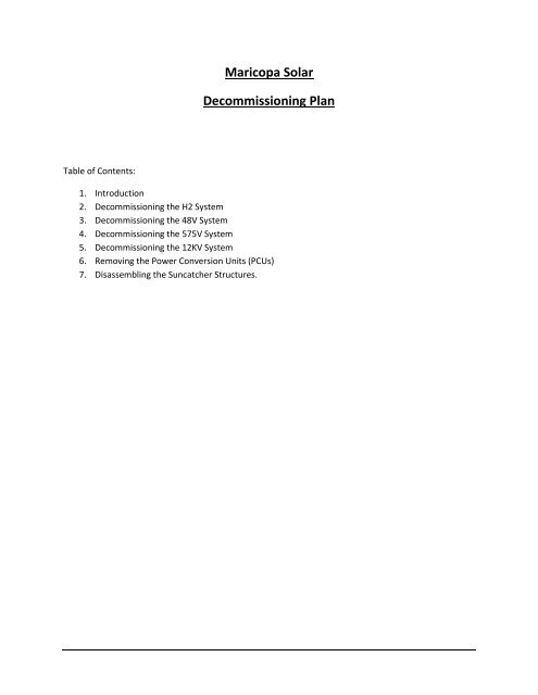
Maricopa Solar Decommissioning Plan - Liquidation Auction ...
Maricopa Solar Decommissioning Plan - Liquidation Auction ...
Maricopa Solar Decommissioning Plan - Liquidation Auction ...

Create successful ePaper yourself
Turn your PDF publications into a flip-book with our unique Google optimized e-Paper software.
<strong>Maricopa</strong> <strong>Solar</strong><br />
<strong>Decommissioning</strong> <strong>Plan</strong><br />
Table of Contents:<br />
1. Introduction<br />
2. <strong>Decommissioning</strong> the H2 System<br />
3. <strong>Decommissioning</strong> the 48V System<br />
4. <strong>Decommissioning</strong> the 575V System<br />
5. <strong>Decommissioning</strong> the 12KV System<br />
6. Removing the Power Conversion Units (PCUs)<br />
7. Disassembling the Suncatcher Structures.
Section 1: Introduction<br />
This document has been prepared to serve as a guideline to assist with the decommissioning of<br />
the <strong>Maricopa</strong> <strong>Solar</strong> power plant. It does not purport to cover all eventualities. Persons performing the<br />
work should adhere to the highest safety standards and personally ensure that all equipment is deenergized<br />
prior to commencing work on any portion of the plant. Only people suitably qualified to work<br />
on electrical, excavation, and heavy-lifting equipment should do so.<br />
As-built drawings should be referred to at all times to ensure correct connections are being<br />
work on. Contractor should refer to the Mortensen and Wilson Electric as – built manuals and drawings.<br />
It is the contractor responsibility to control Lock-Out Tag Out on the site and to ensure that all systems<br />
are truly de-energized before any disassembly takes place.<br />
Material Safety Data sheets are held in the plant control room. The main substances to be aware<br />
of include: Compressed H2, Lubricating Oil, Engine Coolant, Ceramics.<br />
Disclaimer:<br />
"This decommissioning plan sets forth our reasonable estimate, based on known conditions at<br />
the plant, of the procedures needed to take place in order to fully decommission the plant in a<br />
safe and secure manner, returning the land to its prior state. However, there may be<br />
conditions or circumstances that are not known to us that could materially impact the required<br />
procedures necessary to decommission the plant. It is ultimately the responsibility of the<br />
contractor performing the decommissioning work to properly assess all site conditions and to<br />
ensure that all decommissioning work is performed in a safe and secure manner utilizing best<br />
practices."
Section 2 : <strong>Decommissioning</strong> the H2 system.<br />
Overview:<br />
H2 is used as the thermal fluid for the Suncatcher stirling engines. H2 is compressed at the H2<br />
skid and fed through ½ inch tubing to each Suncatcher. Tubing runs in trenches throughout the site.<br />
Refer to the as built drawing for the trench arrangements and layouts.<br />
The H2 systems main components are:<br />
H2 Skid.<br />
H2 In-ground tubing.<br />
H2 On-Suncatcher tubing.<br />
H2 within the Stirling engines.<br />
Safety Concerns:<br />
H2 is a flammable compressed gas. System is maintained under pressure up to 3000 psi.<br />
Voltages are present on the H2 skid up to 575V AC and instrument voltages are fed via the H2 plc .<br />
Applicable MSDS:<br />
Compressed H2<br />
Hydraulic Oil<br />
Coolant<br />
Reference Drawings/Documents:<br />
Hydro-Pac User Manual<br />
As-Built Electrical Drawings (E0 thru E15)<br />
As-Built H2 Distribution Drawings. ( M-000/1/2/3)<br />
Hydro Pac electrical schematic.
H2 Skid:<br />
The 575V should be disconnected at the 50A switch which is located next to the XN100<br />
cabinet and at the H2 control panel MCB. Ensure there is no voltage present on the skid. This<br />
includes control voltages to the instrumentation and the 575V.<br />
All H2 bottles should be closed using the bottle shutoff valve. These bottles will have to<br />
be removed from site by a qualified contractor.<br />
Nitrogen should be introduced to the H2 in ground tubing using the current fill<br />
point for H2. A N2 regulator will be required to do this and N2 bottles will need to be<br />
sourced. All H2 vents at the end of each row should be left open once the purge has<br />
been completed.<br />
The Hydro-Pac compressor contains coolant and hydraulic fluid which should be<br />
drained according to the HydroPac manuals. These fluids should be disposed of in a safe<br />
manner.<br />
Once the in-ground tubing has been purged the two valves shown above should be<br />
closed and all vent lines on the skid should be opened. Individual bottles should be disconnected<br />
from the tubing system. All tubing on the pad should be dismantled to clear the way for the H2<br />
skid to be removed.<br />
1/8 th inch tubing runs from the base of each pedestal to each PCU. These lines should<br />
be disconnected.
H2 pressure in the engines can be released using the SC View program or manually at<br />
the gas management block. Once the engines are vented they can be removed per the PCU<br />
removal instructions – see section 6 .
Section 3: <strong>Decommissioning</strong> the 48V DC system<br />
Overview:<br />
The 48 V DC system is used to drive the dish movements. There are 5 UPS cabinets in the field – one for<br />
each dish group. Batteries are charged via the 575AC system. System voltage for each UPS can be<br />
monitored in the control room. Cabling runs in trenches throughout the site and will have to be<br />
excavated. Refer to the as built drawing for the trench arrangements and layouts.<br />
Safety Concerns:<br />
575 VAC present. 48VDC present.<br />
MSDS: None<br />
Reference Drawings: As built Electrical Dwgs: E1-3; E1-4. Mortensen as built files.<br />
Go to the UPS cabinets and open the breakers feeding each group of 3 dishes. This will remove<br />
the 48V DC supply to the dishes.
Photo: Shows breakers in each UPS to be opened to disconnect 48V DC from the UPS to the dishes.<br />
Disconnect the 575VAC feed to the UPS using the 30A disconnect switch located beside each XN cabinet.<br />
Contractor should remove the 12V batteries and dispose of same in a safe manner.<br />
Note that there will be some residual capacitive charge in the motor amplifiers on each dish. This will<br />
bleed to zero in time but each dish should be checked for this residual charge before work commences<br />
at the dish level.<br />
Go to the 48V DC boxes at each dish and open all breakers. Ensure all voltages are dissipated and<br />
reading 0V before disconnecting any cables. The contractor will have to decide the best way to remove<br />
the cabling from the center of the pedestals. Refer to E 1-4.<br />
There are 12x batteries in each UPS cabinet. Each battery is 12 volt rating. These should be removed and<br />
disposed of in a proper manner prior to lifting the UPS cabinet.
Section 4 : <strong>Decommissioning</strong> the 575 V System<br />
Overview:<br />
The suncatchers generate electricity at 575V AC – 3 phase. Each dish group of 12 feeds into an XN<br />
cabinet which in turn feeds to the 575V bus at the main switch board SWBD 1. Cabling runs in trenches<br />
throughout the site and will have to be excavated. Refer to the as built drawing for the trench<br />
arrangments and layouts.<br />
Safety Concerns: 575 V AC – 3 ph present.<br />
Applicable MSDS: none<br />
Reference Drawings/Documents: E1-2. Mortensen as built drawings.<br />
Open the circuit breakers CB 1 thru 5 which feed to each XN cabinet – photo below.<br />
Open the main 2000 amp circuit breaker – photo below.
Go to each pedestal and ensure all 575 switches are open. Verify no voltage is present before<br />
commencing to undo terminations.
Section 5 : <strong>Decommissioning</strong> the 12 KV system<br />
Overview:<br />
The Suncatcher power is stepped up from 575 to 12.47 KV for supply to the SRP distribution<br />
network. It will be necessary to liaise with SRP to ensure the disconnect switch is open and locked out to<br />
prevent energizing the HV side during decommissioning. Only contractors licensed to work on these high<br />
voltages should be utilized.<br />
Safety Concerns:<br />
Hi Voltage Present<br />
Applicable MSDS: None<br />
Reference Drawings/Documents:<br />
As built electrical drawings. E 1 – 15.<br />
Refer to the as built drawings for the in ground cable runs. It will be necessary to liaise with SRP<br />
for the removal of the SRP supplied 15KV switch and metering equipment.<br />
The S&C supplied breaker should be set to the open position – this can be done using the local<br />
operation mode. Once this is done the metering enclosure and 2000 KVA GSU transformer will be deenergized.<br />
This should be verified before work commences. This will also allow the capicor bank and the<br />
high resistance ground to be disconnected.<br />
Refer to each supplier manual for weights of each cabinet.<br />
Refer to the drawing E4-1 for all HV cable connections.<br />
Refer to drawing E8-1 for conduit plan.<br />
Refer to drawings E 15 -1 thru 6 for cable schedules.<br />
Refer to Mortensen civil drawings for pad construction.
Section 6 : Removing the Power Conversion Units (PCUs)<br />
PCU REMOVAL<br />
1. OVERVIEW<br />
This procedure consists of removing the PCU from the SunCatcher. Normally PCUs are<br />
removed with the Suncatcher in the service position. This will not be possible for<br />
decommissioning purposes. Ensure dish is properly locked out and de-energized. The PCUs<br />
need to be removed from the dishes as they weigh approx. 1300 lb and would adversely affect<br />
the center of gravity if a lift was attempted with the PCU still in place on the dish.<br />
Any crane will need sufficient rating and reach to set up over the 40 ft diameter dish. The PCU<br />
sits approx.. 40 ft. above ground. A manlift will be required to disconnect tubing, 2x retaining<br />
bolts and electrical connections between the PCU and the boom.<br />
2. SUGGESTED TOOLS & EQUIPMENT LIST<br />
DESCRIPTION<br />
QTY<br />
Crane 1<br />
Slings, Eye-to Eye 2<br />
Manlift 1<br />
Impact Gun 1<br />
Torque Wrench 1<br />
Ratchet 1 1/8” Bolts 1<br />
9/16 box wrench for ground strap bolt 1<br />
¾ box wrench for removal of gas line connection 2
Step 1:<br />
Step 2:<br />
Step 3:<br />
Un-latch the PCU dog house cover, to open the PCU cover so that it gives clearance to the PCU lift<br />
slots.<br />
Install qty 2 Hoist Ring on slots located on each side of the PCU and install qty 1 tag line on the<br />
PCU.<br />
Obtain long eye-to-eye sling strap and install Hoist Rings onto the boom truck (or equivalent).<br />
Step 4:<br />
Turn off the H₂ valves to a ¼ turn and relieve H₂ pressure by opening lines half way to let pressure<br />
dissipate. Relieve pressure in engine at the gas management block.<br />
Step 5:<br />
Un-install and remove the following from the SCC Box:<br />
1. SCC Harness from the SCC box (P/N 700211) per Figure 1.<br />
2. 575VAC harness from the SCC box (P/N 700210) per Figure 1.<br />
3. Ground Strap (P/N 700234) per Figure 1.<br />
Step 6:<br />
Step 7:<br />
4. H₂ lines from valves and cap the lines.<br />
Secure the 575VAC and SCC harnesses using zip-ties beside the PCU Boom end.<br />
Remove qty 2 bolts ¾” that secure the PCU to the Boom.<br />
Figure 1 – PCU Removal
Step 8:<br />
Lift the PCU with the crane, un-hook the pins located in the PCU slots until rear members<br />
are not contacting with PCU. Lift and place PCU on truck for removal to area where liquids<br />
can be removed.<br />
Step 9:<br />
Step 10:<br />
Drain lube oil – approx. 2 quarts.<br />
Drain engine coolant – approx. 5 gallons.
Section 7 : Disassembling the Suncatcher Structures<br />
Overview:<br />
Once the PCUs are removed the dish and boom can be lifted as one. The dish boom structure<br />
weights approx. 12,000 lbs. Given the large surface area lifting should be done in low wind conditions,<br />
where the movement of the dish can be controlled. Care must also be given to glint which could cause<br />
significant injury to personnel and damage equipment, including cranes, hoists etc. For this reason it is<br />
recommended that all dish lifts be done at night. If lifts are to be performed during the day then it will<br />
be necessary to cover the mirrored surface.<br />
The pedestals are 36ft long and weigh approx. 4,000 lb. including the azimuth drive. They have<br />
no foundation and have only been pile-driven into the ground. It will be necessary to dig to the side of<br />
the pedestal to dislodge it.<br />
Safety Concerns:<br />
Heavy Lifting<br />
Glint<br />
Applicable MSDS:<br />
Grease – present in gear mechanisms<br />
Reference Drawings/Documents:<br />
Procedure:<br />
SES Dish Installation procedure<br />
Special tooling for lifting the dish/boom assembly is colored orange and is located at the<br />
<strong>Maricopa</strong> site. While this was used during construction, the contractor should ensure it is still fit for use<br />
or acquire another .<br />
Access the center of the pedestal through the port-hole near the top. Release/cut all cables and<br />
tubing running through the center of the pedestal. Remove H2 coils at hub and ensure all cables are free<br />
to be lifted.<br />
Refer to the Installation procedure for the lifting method and attach rigging hardware. Take<br />
tension on the rigging.<br />
Refer to the Dish Installation procedure for bolting layout and remove all bolts.<br />
Once the dish has been safely placed on the ground the boom and yoke should be removed.<br />
Again this must be done at night unless the mirrors are covered. If there is no concern about damaging
the mirrors the contractor may consider flipping the dish to have mirrors facing the ground, once the<br />
boom and yoke are removed.<br />
The mirrors are attached to the structure on 3 pins with a locking nut arrangement. These can<br />
either be unbolted or cut depending on the salvage intentions.
Reference Drawings:<br />
Dish Structure – SES 000032-02<br />
Yoke Assembly – SES 00035-02<br />
Boom Assembly – SES 000040-03<br />
Tube Foundation ( Pedestal ) – SES 000442<br />
PCU Assembly – SES 300175-01<br />
Dish Lifting Instructions – SES procedure 900013-00
8 7 6 5 4 3 2 1<br />
D<br />
29<br />
30<br />
1<br />
4<br />
2<br />
REVISIONS<br />
REV ECN # DESCRIPTION DATE APPROVED<br />
01 000076 INITIAL RELEASE 04-01-09<br />
02 000227 UPDATE FOUNDATION PN 8-19-09<br />
D<br />
C<br />
B<br />
A<br />
5. ITEM TO BE SECURED UNDER MOTOR MOUNTING<br />
BOLT HEAD (2 PLACES).<br />
4. MAXIMUN QTY SHOWN. ACTUAL QTY AND AREA<br />
ARRANGMENT TO BE SPECIFIED PER SITE SPECIFIC<br />
REQUIERMENTS.<br />
3. LOWER EDGE OF ITEM 25 TO BE FLUSH<br />
WITH LOWER EDGE OF ITEM 27.<br />
2. TORQUE ALL FASTENERS PER 000301.<br />
1. MASS: 13740 LB (REF).<br />
NOTES: UNLESS OTHERWISE SPECIFIED.<br />
8<br />
7<br />
6<br />
5<br />
7<br />
4<br />
4<br />
4<br />
30 1<br />
29 KIT. CONDUIT BRKTS 1<br />
28 000424 ASSY, WIRE RACEWAY, POWER 1<br />
27 KIT, H2 LINES AND BRKTS 1<br />
26 KIT, SENSOR BRKTS 1<br />
25 000300 BOLT,HEX .75-10 X 3.00 LG 16<br />
24 SCREW, SOCKET HEAD CAP .75-10 X 2.25 10<br />
23 000406 ASSY, WIRE RACEWAY, CONTROLS 1<br />
22 000263 PIN, COTTER, .25 X 2.5 1<br />
21 000404 KIT, GLINT SHILED 1<br />
30 000043 ASSY, OUTER FACET 27<br />
29 000042 ASSY, INNER FACET 13<br />
21 000259 HEX NUT .75-10 37<br />
20 000260 WASHER, FLAT .75 51<br />
19 000371 BOLT, HEX .75-10 x 7.50 LG 4<br />
17 000118 BOLT, HEX .75-10 x 2.25 LG 21<br />
16 000258 BOLT, HEX .75-10 x 1.5 LG 8<br />
13 000030 ASSY, AZIMUTH DRIVE 1<br />
12 000257 PLATE, AXLE 4<br />
11 000272 WASHER, THRUST, TRUNNION 2<br />
10 000127 WASHER, THRUST, YOKE 2<br />
9 000028 ASSY, ELEVATION DRIVE 1<br />
8 000262 PIN, CLEVIS, YOKE 1<br />
7 000446 ASSY, FOUNDATION MARICOPA PLANT 1<br />
6 000037 ASSY, TRUNNION 1<br />
5 000035 ASSY, YOKE 1<br />
4 000039 ASSY, PILLOW BLOCK, TRUNNION 2<br />
3 000038 ASSY, PILLOW BLOCK, YOKE 2<br />
2 000040 ASSY, BOOM 1<br />
1 000041 ASSY, FACET SUPPORT STRUCTURE 1<br />
ITEM NUMBER DESCRIPTION QTY<br />
UNLESS OTHERWISE SPECIFIED:<br />
NAME DATE<br />
DIMENSIONS ARE IN INCHES<br />
TOLERANCES:<br />
ANGLE: .5<br />
.X = 0.1<br />
.XX = 0.03<br />
.XXX= 0.010<br />
ALL FRACTION<br />
TOLERANCES 1/16"<br />
INTERPRET PER: ASME Y14.5<br />
MATERIAL<br />
NOTED<br />
FINISH<br />
NONE<br />
DO NOT SCALE DRAWING<br />
3<br />
DRAWN<br />
CHECKED<br />
APPROVED<br />
SKRELL 12-15-08<br />
PROPRIETARY AND CONFIDENTIAL<br />
THE INFORMATION CONTAINED IN THIS<br />
DRAWING IS THE SOLE PROPERTY OF<br />
STIRLING ENERGY SYSTEMS. ANY<br />
REPRODUCTION IN PART OR AS A WHOLE<br />
WITHOUT THE WRITTEN PERMISSION OF<br />
STIRLING ENERGY SYSTEMS IS<br />
PROHIBITED.<br />
2<br />
TITLE:<br />
P/N:<br />
ASSY, DISH<br />
CONCENTRATOR<br />
REV<br />
000032 02<br />
APPLICATION:<br />
SCALE: 1:80<br />
SUN CATCHER GEN 1<br />
SHT 1 OF 4<br />
1<br />
SIZE<br />
B<br />
C<br />
B<br />
A
8 7 6 5 4 3 2 1<br />
12<br />
2X<br />
16<br />
2X<br />
D<br />
10X<br />
20<br />
24<br />
20<br />
4X<br />
19<br />
2X 10<br />
3<br />
2X<br />
D<br />
25<br />
20<br />
21<br />
8X<br />
C<br />
13<br />
YOKE<br />
PIVOT<br />
C<br />
B<br />
16X<br />
?<br />
?<br />
?<br />
5<br />
8<br />
B<br />
2X<br />
11<br />
25<br />
20<br />
21<br />
8X<br />
4<br />
2X<br />
A<br />
8<br />
22<br />
7<br />
6<br />
5<br />
4<br />
12 2X 16<br />
TRUNNION<br />
PIVOT<br />
2X<br />
3<br />
PROPRIETARY AND CONFIDENTIAL<br />
THE INFORMATION CONTAINED IN THIS<br />
DRAWING IS THE SOLE PROPERTY OF<br />
STIRLING ENERGY SYSTEMS. ANY<br />
REPRODUCTION IN PART OR AS A WHOLE<br />
WITHOUT THE WRITTEN PERMISSION OF<br />
STIRLING ENERGY SYSTEMS IS<br />
PROHIBITED.<br />
2<br />
TITLE:<br />
P/N:<br />
ASSY, DISH<br />
CONCENTRATOR<br />
APPLICATION:<br />
000032<br />
SUN CATCHER GEN 1<br />
SCALE: 1:192 SHT 2 OF 4<br />
1<br />
REV<br />
02<br />
SIZE<br />
B<br />
A
8 7 6 5 4 3 2 1<br />
D<br />
21<br />
6<br />
D<br />
C<br />
5<br />
21<br />
9<br />
16<br />
4X<br />
C<br />
3X<br />
21<br />
17 20 21<br />
1<br />
B<br />
2<br />
B<br />
17 20 21<br />
18X<br />
A<br />
8<br />
7<br />
6<br />
5<br />
4<br />
3<br />
PROPRIETARY AND CONFIDENTIAL<br />
THE INFORMATION CONTAINED IN THIS<br />
DRAWING IS THE SOLE PROPERTY OF<br />
STIRLING ENERGY SYSTEMS. ANY<br />
REPRODUCTION IN PART OR AS A WHOLE<br />
WITHOUT THE WRITTEN PERMISSION OF<br />
STIRLING ENERGY SYSTEMS IS<br />
PROHIBITED.<br />
2<br />
TITLE:<br />
P/N:<br />
ASSY, DISH<br />
CONCENTRATOR<br />
APPLICATION:<br />
000032<br />
SUN CATCHER GEN 1<br />
SCALE: 1:192 SHT 3 OF 4<br />
1<br />
REV<br />
02<br />
SIZE<br />
B<br />
A
8 7 6 5 4 3 2 1<br />
D<br />
A<br />
A<br />
D<br />
2X (55 1/4")<br />
ITEMS 26 & 27<br />
3<br />
12 3/8"<br />
C<br />
C<br />
B<br />
B<br />
2X (1 1/8")<br />
LEFT & RIGHT<br />
SIDES<br />
A<br />
8<br />
7<br />
PARTIAL SECTION A-A<br />
SCALE 1 : 50<br />
ITEMS OMITTED FOR CLARITY<br />
6<br />
5<br />
4<br />
2X (37 7/16")<br />
LEFT AND RIGHT SIDES<br />
3<br />
GLINT SHIELD<br />
POSITIONS<br />
PROPRIETARY AND CONFIDENTIAL<br />
THE INFORMATION CONTAINED IN THIS<br />
DRAWING IS THE SOLE PROPERTY OF<br />
STIRLING ENERGY SYSTEMS. ANY<br />
REPRODUCTION IN PART OR AS A WHOLE<br />
WITHOUT THE WRITTEN PERMISSION OF<br />
STIRLING ENERGY SYSTEMS IS<br />
PROHIBITED.<br />
2<br />
TITLE:<br />
P/N:<br />
ASSY, DISH<br />
CONCENTRATOR<br />
000032<br />
APPLICATION:<br />
SUN CATCHER GEN 1<br />
SCALE: 1:192 SHT 4 OF 4<br />
1<br />
REV<br />
02<br />
SIZE<br />
B<br />
A
8 7 6 5 4 3 2 1<br />
REVISIONS<br />
REV ECN # DESCRIPTION DATE APPROVED<br />
01 N/A INITIAL RELEASE 11-24-08 S.K.<br />
02 000076 REVISED FOR CLARITY 4-1-09 E.B.<br />
D<br />
D<br />
2<br />
2X<br />
3<br />
2X 2 3<br />
C<br />
C<br />
B<br />
B<br />
1<br />
3 000267 SCREW, SET, SOCKET HEAD, AXLE, YOKE 2<br />
2 000083 AXLE, YOKE 2<br />
1 000082 YOKE, MACHINED 1<br />
A<br />
4. APPLY P/N 000128, A/R, TO AREA SHOWN PRIOR<br />
TO ASSEMBLY.<br />
3. APPLY THREADLOCKER, LOCTITE 262 OR EQUIV.,<br />
A/R, PER MANUFACTURER'S INSTRUCTIONS,<br />
TO ITEM 3 PRIOR TO ASSEMBLY.<br />
2. TORQUE TO 320 FT. LB. ABOVE RUNNING TORQUE.<br />
1. MASS: 388 LB (REF).<br />
NOTES: UNLESS OTHERWISE SPECIFIED.<br />
8<br />
7<br />
6<br />
2.00 3.00<br />
4<br />
DETAIL ITEM 2<br />
5<br />
4<br />
ITEM NUMBER DESCRIPTION QTY.<br />
UNLESS OTHERWISE SPECIFIED:<br />
DIMENSIONS ARE IN INCHES<br />
TOLERANCES:<br />
ANGLE: .5<br />
.X = 0.1<br />
.XX = 0.03<br />
.XXX= 0.010<br />
ALL FRACTION<br />
TOLERANCES 1/16"<br />
INTERPRET PER: ASME Y14.5M-1994<br />
MATERIAL<br />
N/A<br />
FINISH<br />
N/A<br />
DO NOT SCALE DRAWING<br />
3<br />
DRAWN<br />
CHECKED<br />
APPROVED<br />
NAME<br />
DATE<br />
S. KRELL 11-24-08<br />
PROPRIETARY AND CONFIDENTIAL<br />
THE INFORMATION CONTAINED IN THIS<br />
DRAWING IS THE SOLE PROPERTY OF<br />
STIRLING ENERGY SYSTEMS. ANY<br />
REPRODUCTION IN PART OR AS A WHOLE<br />
WITHOUT THE WRITTEN PERMISSION OF<br />
STIRLING ENERGY SYSTEMS IS<br />
PROHIBITED.<br />
2<br />
TITLE:<br />
P/N:<br />
APPLICATION:<br />
SCALE: 1:8<br />
ASSY, YOKE<br />
000035<br />
SHT 1 OF 1<br />
1<br />
SES<br />
REV<br />
02<br />
SIZE<br />
B<br />
A
8 7 6 5 4 3 2 1<br />
REV ECN # DESCRIPTION DATE APPROVED<br />
01 000014 INITIAL RELEASE 11-20-08<br />
02 000048 REVISED AND REDRAWN. 04-01-09<br />
03 000105 REVISED HOLES/SLOTS FOR CABLING. 5-14-09 EB<br />
D<br />
22<br />
D<br />
21<br />
76X<br />
23<br />
21<br />
7<br />
20<br />
2X<br />
C<br />
5<br />
17<br />
14<br />
19<br />
2X<br />
13<br />
4<br />
24 000292 L CHANNEL, SUPPORT 4, BOOM 1<br />
23 000291 BOLT, HEX, .50-13 X 1.50 LG, GRADE 5 76<br />
22 000290 NUT, HEX .50-13, TOP LOCK 76<br />
21 000284 WELDMENT, BRACE, HUB, IB 1<br />
20 000275 L CHANNEL, X-BRACE 2, UPPER 2<br />
19 000274 L CHANNEL, X-BRACE 1, UPPER 2<br />
C<br />
3<br />
18 000255 WASHER, FLAT, 1/2" 76<br />
17 000185 PLATE, INNER, OUTER BOOM SUPPORT 1<br />
16 000184 L CHANNEL, LOWER SUPPORT, FRONT, BOOM 1<br />
15 000180 L CHANNEL, SUPPORT 3, BOOM 1<br />
B<br />
A<br />
24<br />
15<br />
16 12<br />
2. TORQUE ALL FASTENERS PER 000301.<br />
1. MASS: 2034 LB (REF).<br />
NOTES: UNLESS OTHERWISE SPECIFIED.<br />
8<br />
2X<br />
7<br />
11<br />
2X<br />
9<br />
2X<br />
6<br />
2X<br />
10<br />
8<br />
2X<br />
5<br />
6<br />
4<br />
14 000179 L CHANNEL, SUPPORT 2, BOOM 1<br />
13 000178 L CHANNEL, SUPPORT 1, BOOM 1<br />
12 000177 L CHANNEL, X-BRACE 5 2<br />
11 000176 L CHANNEL, X-BRACE 4 2<br />
10 000175 L CHANNEL, X-BRACE 3 2<br />
9 000174 L CHANNEL, X-BRACE 2 2<br />
8 000173 L CHANNEL, X-BRACE 1 2<br />
7 000172 C CHANNEL, UPPER CHORD, BOOM, LH 1<br />
6 000171 C CHANNEL, UPPER CHORD, BOOM, RH 1<br />
5 000131 ASSY, OUTER BOOM 1<br />
4 000130 ASSY, INNER BOOM, LH 1<br />
3 000129 ASSY, INNER BOOM, RH 1<br />
ITEM NUMBER DESCRIPTION QTY<br />
UNLESS OTHERWISE SPECIFIED:<br />
DIMENSIONS ARE IN INCHES<br />
TOLERANCES:<br />
ANGLE: .5<br />
.X = 0.1<br />
.XX = 0.03<br />
.XXX= 0.010<br />
ALL FRACTION<br />
TOLERANCES 1/16"<br />
INTERPRET PER: ASME Y14.5M-1994<br />
MATERIAL<br />
N/A<br />
FINISH<br />
N/A<br />
DO NOT SCALE DRAWING<br />
3<br />
DRAWN<br />
CHECKED<br />
APPROVED<br />
NAME<br />
DATE<br />
S. KRELL 11-20-08<br />
PROPRIETARY AND CONFIDENTIAL<br />
THE INFORMATION CONTAINED IN THIS<br />
DRAWING IS THE SOLE PROPERTY OF<br />
STIRLING ENERGY SYSTEMS. ANY<br />
REPRODUCTION IN PART OR AS A WHOLE<br />
WITHOUT THE WRITTEN PERMISSION OF<br />
STIRLING ENERGY SYSTEMS IS<br />
PROHIBITED.<br />
2<br />
TITLE:<br />
P/N:<br />
APPLICATION:<br />
SCALE: 1:35<br />
ASSY, BOOM<br />
000040<br />
SUN CATCHER GEN 1<br />
SHT 1 OF 3<br />
1<br />
REV<br />
03<br />
SIZE<br />
B<br />
B<br />
A
8 7 6 5 4 3 2 1<br />
D<br />
17 19 2X 20 2X<br />
"A"<br />
5<br />
D<br />
DETAIL D<br />
SCALE 1 : 24<br />
C<br />
5<br />
C<br />
A<br />
D<br />
B<br />
11<br />
C<br />
10<br />
E<br />
17.54<br />
A - B<br />
"B"<br />
F<br />
12<br />
B<br />
A<br />
B<br />
C<br />
254.96<br />
A - B<br />
F<br />
13.5°<br />
6.8°<br />
3<br />
B<br />
DETAIL E<br />
SCALE 1 : 16<br />
16 9 2X 8 2X<br />
2.50°<br />
A<br />
5.00°<br />
TITLE:<br />
ASSY, BOOM<br />
A<br />
8<br />
7<br />
6<br />
5<br />
4<br />
3<br />
PROPRIETARY AND CONFIDENTIAL<br />
THE INFORMATION CONTAINED IN THIS<br />
DRAWING IS THE SOLE PROPERTY OF<br />
STIRLING ENERGY SYSTEMS. ANY<br />
REPRODUCTION IN PART OR AS A WHOLE<br />
WITHOUT THE WRITTEN PERMISSION OF<br />
STIRLING ENERGY SYSTEMS IS<br />
PROHIBITED.<br />
2<br />
P/N:<br />
APPLICATION:<br />
000040<br />
SUN CATCHER GEN 1<br />
SCALE: 1:35 SHT 2 OF 3<br />
1<br />
REV<br />
03<br />
SIZE<br />
B
8 7 6 5 4 3 2 1<br />
D<br />
D<br />
13<br />
15<br />
2X<br />
10<br />
2X<br />
12<br />
C<br />
C<br />
21<br />
SECTION A-A<br />
SCALE 1 : 25<br />
ITEMS REMOVED<br />
FOR CLARITY<br />
SECTION C-C<br />
SCALE 1 : 25<br />
ITEMS REMOVED<br />
FOR CLARITY<br />
14<br />
B<br />
B<br />
4<br />
2X<br />
14<br />
20 2X<br />
A<br />
8<br />
SECTION F-F<br />
SCALE 1 : 25<br />
ITEMS REMOVED<br />
FOR CLARITY<br />
7<br />
6<br />
5<br />
SECTION B-B<br />
SCALE 1 : 25<br />
ITEMS REMOVED<br />
FOR CLARITY<br />
4<br />
3<br />
PROPRIETARY AND CONFIDENTIAL<br />
THE INFORMATION CONTAINED IN THIS<br />
DRAWING IS THE SOLE PROPERTY OF<br />
STIRLING ENERGY SYSTEMS. ANY<br />
REPRODUCTION IN PART OR AS A WHOLE<br />
WITHOUT THE WRITTEN PERMISSION OF<br />
STIRLING ENERGY SYSTEMS IS<br />
PROHIBITED.<br />
2<br />
TITLE:<br />
P/N:<br />
APPLICATION:<br />
ASSY, BOOM<br />
000040<br />
SUN CATCHER GEN 1<br />
SCALE: 1:35 SHT 3 OF 3<br />
1<br />
REV<br />
03<br />
SIZE<br />
B<br />
A
8 7 6 5 4 3 2 1<br />
D<br />
1.25 THRU<br />
NEAR SIDE<br />
3/8-16 UNC<br />
THRU NEAR SIDE<br />
0<br />
3.0<br />
4.5<br />
12.0<br />
.375 NOM<br />
REVISIONS<br />
REV ECN # DESCRIPTION DATE APPROVED<br />
01 000227 INITIAL RELEASE 8-19-09<br />
D<br />
12.94 THRU<br />
NEAR SIDE<br />
24.00±.24<br />
0<br />
0<br />
C<br />
5.69 THRU<br />
NEAR SIDE<br />
C<br />
3/8-16 UNC<br />
THRU NEAR SIDE<br />
180.5<br />
198.5<br />
See Note 3<br />
B<br />
1/8<br />
45°<br />
B<br />
389.8<br />
.50<br />
1.00<br />
23.25" OD X 1/8" THK<br />
A<br />
1. MATERIAL: STEEL PER ASTM A53 GRADE 50 (HYDRAULIC TEST NOT REQUIRED)<br />
2. OPTIONAL MATERIAL: ASTM A252, GRADE 50<br />
3. OPTIONAL SPLICING: FULL PENETRATION WELD PER ANSI-AWS D1.1 2006<br />
4. MASS: 3418 LB (REF).<br />
NOTES: UNLESS OTHERWISE SPECIFIED.<br />
8<br />
7<br />
6<br />
5<br />
437.8 1.0<br />
VIEW<br />
4<br />
UNLESS OTHERWISE SPECIFIED:<br />
DIMENSIONS ARE IN INCHES<br />
TOLERANCES:<br />
ANGLE: .5<br />
.X = 0.1<br />
.XX = 0.03<br />
.XXX= 0.010<br />
INTERPRET PER: ASME Y14.5<br />
MATERIAL<br />
FINISH<br />
ALL FRACTION<br />
TOLERANCES 1/16"<br />
SEE NOTES<br />
N/A<br />
DO NOT SCALE DRAWING<br />
3<br />
DRAWN<br />
CHECKED<br />
APPROVED<br />
NAME<br />
DATE<br />
BN 8-19-09<br />
PROPRIETARY AND CONFIDENTIAL<br />
THE INFORMATION CONTAINED IN THIS<br />
DRAWING IS THE SOLE PROPERTY OF<br />
STIRLING ENERGY SYSTEMS. ANY<br />
REPRODUCTION IN PART OR AS A WHOLE<br />
WITHOUT THE WRITTEN PERMISSION OF<br />
STIRLING ENERGY SYSTEMS IS<br />
PROHIBITED.<br />
2<br />
TITLE:<br />
TUBE, FOUNDATION FEATURES<br />
MARICOPA PLANT<br />
P/N:<br />
APPLICATION:<br />
SCALE: 1:24<br />
000442<br />
SUN CATCHER GEN 1<br />
SHT 1 OF 1<br />
1<br />
REV<br />
01<br />
SIZE<br />
B<br />
A
MARICOPA SOLAR<br />
DISH LIFT<br />
DOC. NO. 900013<br />
REV 00<br />
Stirling Energy Systems, Inc.<br />
4800 North Scottsdale Road, Ste. 5500 -<br />
Scottsdale, AZ 85261<br />
This document and all information and expression contained herein are the property and copyright of Stirling<br />
Energy Systems (SES), Inc., are loaned in confidence, and may not, in whole or in part, be used, duplicated, or<br />
disclosed for any purpose without prior written consent from Stirling Energy Systems, Inc. All rights reserved.<br />
All print versions and any electronic version of this document outside the SES configuration management controlled<br />
repository are uncontrolled documentation.
REVISIONS<br />
Author: Yariela Mejia Created : 01/08/2010<br />
Doc. Title Dish Lift Doc No. 900013<br />
REV RFA DESCRIPTION DATE APPROVAL<br />
00 900013 INITIAL RELEASE 3/2/2010 SD<br />
<strong>Maricopa</strong> <strong>Solar</strong><br />
SES Proprietary -See Title Page for Details Page 2 of 16
SUNCATCHER BUILD INSTRUCTIONS<br />
DOC. NO. 900013<br />
TABLE OF CONTENTS<br />
DISH LIFT .......................................................................................................................... 4<br />
1. OVERVIEW .............................................................................................................. 4<br />
2. PART LIST ............................................................................................................... 5<br />
3. TOOLS & EQUIPMENT LIST ..................................................................................... 6<br />
4. SAFETY KEY POINTS ................................................................................................ 7<br />
5. QUALITY KEY POINTS .............................................................................................. 8<br />
6. DISH LIFT ................................................................................................................ 9<br />
6.1. SUNCATCHER DISH LIFT SET-UP ....................................... 9<br />
6.2. DISH LIFT PROCESS ........................................................ 13<br />
6.3. INSTALL YOKE HARDWARE ON SOUTH SIDE .................. 15<br />
<strong>Maricopa</strong> <strong>Solar</strong><br />
SES Proprietary -See Title Page for Details Page 3 of 16
SUNCATCHER BUILD INSTRUCTIONS<br />
DOC. NO. 900013<br />
DISH LIFT<br />
1. OVERVIEW<br />
This build instruction details the process to lift the assembled Facet Support<br />
Structure with Facets. The installation procedure to assemble the dish on the<br />
pedestal of the SunCatcher is part of this instructional manual.<br />
I. Dish Lift Set-Up<br />
II.<br />
III.<br />
Dish Lift Process<br />
Install Yoke on Pedestal<br />
Ensure to read the instruction manual, understand the build sequence before<br />
commencement of build. Pay special attention to all safety and quality alerts to<br />
ensure a safe environment, quality, and risk-free product.<br />
<strong>Maricopa</strong> <strong>Solar</strong><br />
SES Proprietary -See Title Page for Details Page 4 of 16
SUNCATCHER BUILD INSTRUCTIONS<br />
DOC. NO. 900013<br />
2. PART LIST<br />
PART NO. PART DESCRIPTION QTY<br />
000446 Assembly, Foundation, SunCatcher 1<br />
Facet Support Structure & Facets 1<br />
SCREW, SOCKET HEAD CAP .75-10 X 2.25” 10<br />
000260 WASHER, FLAT .75” 10<br />
000371 SCREW, SOCKET HEAD CAP .75-10 X 7.5” 4<br />
<strong>Maricopa</strong> <strong>Solar</strong><br />
SES Proprietary -See Title Page for Details Page 5 of 16
SUNCATCHER BUILD INSTRUCTIONS<br />
DOC. NO. 900013<br />
3. TOOLS & EQUIPMENT LIST<br />
DESCRIPTION<br />
QTY<br />
2” x 4 Ply x 22’ Long Eye-to-Eye Slings –Main Sling 2<br />
2” x 4 Ply x 18’ Long Eye-to-Eye Slings –Main Sling 2<br />
1 ¼” Shackle –Main Sling 2<br />
2” x 4 Ply x 20’ Long Eye-to-Eye Slings –Hub Stabilizer Sling 2<br />
3 Ton Come-A-Longs 2<br />
¾” Hoist Rings 4<br />
3” x 4 Ply x 2’ Long Endless Sling 2<br />
2” x 4 Ply x 5’ Long Eye-to-Eye Slings –Boom Stabilizer Sling 2<br />
¾-10 Grade 8 Nuts 2<br />
Tag Lines 50’ 4<br />
¾” Six Point Socket for ¾” Drive 1<br />
Man Lift 2<br />
Crane 1<br />
Loctite 242<br />
A/R<br />
Paint marker<br />
A/R<br />
Sockets (15/16) 1<br />
Torque Wrench (3/4 drive) 1<br />
Impact wrench (3/4”) 1<br />
Impact wrench (1/2”) 1<br />
Allen wrench (5/8 x ½”) 1<br />
Reducer (3/4 x ½”) 1<br />
<strong>Maricopa</strong> <strong>Solar</strong><br />
SES Proprietary -See Title Page for Details Page 6 of 16
SUNCATCHER BUILD INSTRUCTIONS<br />
DOC. NO. 900013<br />
4. SAFETY KEY POINTS<br />
Review the Safety key points below, these Safety points are to be followed at all<br />
times. There are additional safety notes throughout the build instructions which<br />
will notify and alert the reader of hazardous activities and/or precautions where<br />
there must be specific care.<br />
• Personal Protective Equipment (PPE) must be worn at all times.<br />
o Sturdy leather work boots (Steel Toe Shoes)<br />
o Safety Vest<br />
o Safety Eyewear (Z87 ANSI rated)<br />
o Safety Gloves<br />
o Safety Hard Hat (Z94)<br />
o Ear Plugs (when applicable)<br />
o Safety Harness with SRL’s (or adjustable lanyards)<br />
• Caution with predictable hand injuries:<br />
o Caution with pinch points.<br />
o Caution with sharp points.<br />
o Caution with hot items.<br />
o Caution with rough items.<br />
• No one shall be located under a Load (i.e. crane load, crane boom, man<br />
lift, forklift load, etc.).<br />
• Pay attention and follow instructed Safety Alerts (i.e. Warning).<br />
• Qualified operators can only operate forklift, manlift, crane, etc.<br />
• Ear Plugs must be worn if noise is above 85 dB.<br />
<strong>Maricopa</strong> <strong>Solar</strong><br />
SES Proprietary -See Title Page for Details Page 7 of 16
5. QUALITY KEY POINTS<br />
SUNCATCHER BUILD INSTRUCTIONS<br />
DOC. NO. 900013<br />
Main quality key points are called-out throughout the build instructions, these call<br />
outs are quality alerts that need to be address at a certain time of the build.<br />
Confirm, Verify, and Inspect are quality key words that signal check points either<br />
before or after performing a task or step. Review the key points below so that<br />
when quality key points appear in the instructions you are aware when check<br />
points need to be perform.<br />
CONFIRM: check point activity that need to be performed before a step of build.<br />
VERIFY: check point activity that must be performed after a step of build.<br />
INSPECT: checkpoint activity that must be performed when indicated during build<br />
in the QA Check Sheet Traveler.<br />
<strong>Maricopa</strong> <strong>Solar</strong><br />
SES Proprietary -See Title Page for Details Page 8 of 16
SUNCATCHER BUILD INSTRUCTIONS<br />
DOC. NO. 900013<br />
6. DISH LIFT<br />
6.1. SUNCATCHER DISH LIFT SET-UP<br />
Step 1:<br />
Step 2:<br />
Step 3:<br />
Review the entire lift plan before commencing any work between<br />
assembly and crane crew. Layout crane position.<br />
Move Crane into position.<br />
Assembly crew perform a visual sweep of the SunCatcher Dish by<br />
checking the following:<br />
1. Verify all rivets are securely installed.<br />
2. Verify all Facet stud rings are securely installed.<br />
3. Verify there are no loose components on dish.<br />
4. Verify Yoke Lifting Bracket is installed.<br />
5. Verify Hub Hoist Rings are installed.<br />
6. Confirm Alignment Pins are installed on Azimuth drive.<br />
7. Confirm Alignment Spears are installed on Azimuth drive.<br />
Step 4:<br />
Step 5:<br />
Install qty 2 tag lines on FSS dish on opposite sides of the dish,<br />
usually on East and West sides.<br />
Using a manlift, install 3 point tie-outs (see Figure 4) per the<br />
following locations:<br />
Step 5.1. Install Hub Stabilizer Slings on opposite side of hub opening (Figure 1).<br />
a. Obtain qty 2 Hoist Rings and install on the opposite side of the Hub<br />
opening, if not installed.<br />
b. Obtain qty 2 (2” x 4 Ply x 20’) Long Eye-to-Eye Slings –Hub Stabilizer<br />
Slings and install one to each hoist ring.<br />
c. Install Sling to Crane 3 Ton Come-A-Long.<br />
<strong>Maricopa</strong> <strong>Solar</strong><br />
SES Proprietary -See Title Page for Details Page 9 of 16
SUNCATCHER BUILD INSTRUCTIONS<br />
DOC. NO. 900013<br />
Figure 1 – Install Hub Stabilizer Tie-Out<br />
Step 5.2. Install Lifting bracket on Yoke, if not installed (Figure 2).<br />
a. Obtain qty 2 hoist rings and install on each side of the the yoke lifting<br />
bracket.<br />
b. Install qty 2 (2” x 4 Ply x 20’) long eye-to-eye slings on additional qty 2<br />
hoist rings to install to yoke lifting device.<br />
c. Install Sling to Crane 3 Ton Come-A-Long.<br />
Figure 2 –Yoke Lifting Bracket<br />
<strong>Maricopa</strong> <strong>Solar</strong><br />
SES Proprietary -See Title Page for Details Page 10 of 16
Step 5.3. PCU Outer Boom end, as indicated in Figure 3.<br />
SUNCATCHER BUILD INSTRUCTIONS<br />
DOC. NO. 900013<br />
a. Obtain qty 1 (2”x 4 Ply x 8’) long Eye-to-Eye sling to PCU Boom outer<br />
cross-bar per Figure 3.<br />
b. Install qty 2 (2” x 4 Ply x 20’) long eye-to-eye slings to qty 2 hoist rings<br />
on yoke lifting device.<br />
c. Install Sling to Crane 3 Ton Come-A-Long.<br />
Figure 3 – Install PCU Outer Boom Cross-Bar Tie-Out<br />
<strong>Maricopa</strong> <strong>Solar</strong><br />
SES Proprietary -See Title Page for Details Page 11 of 16
SUNCATCHER BUILD INSTRUCTIONS<br />
DOC. NO. 900013<br />
PCU Boom<br />
Cross-Bar End<br />
Tie-out<br />
Yoke Lift<br />
Bracket Tie-out<br />
Hoist Rings Tieout<br />
on Hub<br />
Figure 4 – Install Dish Tie-Outs<br />
CONFIRM: Wind Speed must be ≤ 10 mphbefore lifting dish to pedestal.<br />
Step 6:<br />
Manlift operator must check that wind speed is 10 mph or below, to lift dish with<br />
the crane.<br />
- If wind speed is > 10 mph, wait until it is ≤ 10 mph.<br />
- If wind speed is ≤ 10 mph continue to the next Step.<br />
Step 7:<br />
Obtain a ladder and place on the Hub opening (south) to remove qty 4 bolts on<br />
the Yoke, securing it to the Assembly stand.<br />
<strong>Maricopa</strong> <strong>Solar</strong><br />
SES Proprietary -See Title Page for Details Page 12 of 16
VERIFY: Tag lines are in place as crane lifts dish to set on pedestal.<br />
6.2. DISH LIFT PROCESS<br />
SUNCATCHER BUILD INSTRUCTIONS<br />
DOC. NO. 900013<br />
Step 8:<br />
Lift the dish over the pedestal with the crane. The Hub opening<br />
must remain facing south during the lift using the Tag Lines to<br />
stabilize dish. Reference Figure 5.<br />
Figure 5 – Dish Lift<br />
Step 9:<br />
Lower the dish until the bottom of the yoke is 1’-2’ above the top<br />
pedestal flange.<br />
Step 10: On the manlift, guide the dish down as the hub is moved such that<br />
the base of the Yoke slips into the Yoke Alignment Pins and then<br />
down over the Alignment Spears. Reference Figure 6.<br />
Step 11: Once the load is supported on the pedestal, install the hardware<br />
through the Yoke into the Azimuth Drive, using the manlift.<br />
<strong>Maricopa</strong> <strong>Solar</strong><br />
SES Proprietary -See Title Page for Details Page 13 of 16
SUNCATCHER BUILD INSTRUCTIONS<br />
DOC. NO. 900013<br />
Alignment<br />
Spears<br />
Yoke Alignment<br />
Pins<br />
Figure 6 – Align Yoke on Pedestal<br />
Step 12: Remove Alignment Spears from the Azimuth Drive. Reference<br />
Figure 6.<br />
INSTALL YOKE HARDWARE ON NORTH SIDE<br />
Step 13: Obtain qty 7 (¾”x 2.25”long) socket head cap screws, apply Loctite<br />
242 (or equivalent) and install, using an impact gun on the North<br />
side of Yoke. Do not torque at this time. Reference Figure 7.<br />
Step 14: Obtain 2 ( ¾”x7.5”long) socket head cap screws, apply Loctite 242<br />
(or equivalent), and install using an impact gun on the North side of<br />
the Yoke. Do not torque at this time. Reference Figure 7.<br />
Step 15: Torque qty 9 Yoke hardware to 300 ft-lbs, per 000301. Apply a<br />
stripe on bolts using a paint marker.<br />
VERIFY: Stripe bolts are applied for torque QA.<br />
<strong>Maricopa</strong> <strong>Solar</strong><br />
SES Proprietary -See Title Page for Details Page 14 of 16
6.3. INSTALL YOKE HARDWARE ON SOUTH SIDE<br />
SUNCATCHER BUILD INSTRUCTIONS<br />
DOC. NO. 900013<br />
Step 16: Obtain Apply Loctite 242 (or equivalent) and install, using an impact<br />
gun, qty 3 (¾”x 2.25” long) socket head cap screws on the South<br />
side of the Yoke. Reference Figure 7. Do not torque at this time.<br />
Step 17: Obtain qty 2 (¾”x7.5” long) socket head cap screws, apply loctite<br />
242 (or equivalent), and install using an impact gun on the South<br />
side of the Yoke. Do not torque at this time. Reference Figure 7.<br />
Step 18: Torque qty 5 Yoke hardware to 300 ft-lbs, per 000301. Apply a<br />
stripe on bolts using a paint marker.<br />
VERIFY: Stripe bolts are applied for torque QA.<br />
Install Hex Bolt<br />
¾”x7.5”long<br />
(Qty 2, North Side)<br />
Install socket head<br />
cap screws<br />
¾”x2.25” long<br />
(Qty 7, North Side)<br />
Install Hex Bolt<br />
¾”x7.5”long<br />
(Qty 2, South Side)<br />
Install Bolts<br />
¾”x2.25” long<br />
(Qty 3, South Side)<br />
Figure 7 – Install Yoke Hardware (South View)<br />
Step 19: Remove the Yoke Alignment Pins from the Azimuth drive (Figure 6)<br />
and insert the qty 4 Socket Head Cap Screws (5/8 x 2 ½”) back on<br />
where alignment pins used to be.<br />
Step 20: Torque Azimuth qty 4 bolts to 168 ft-lbs. Apply a stripe on hardware<br />
using a paint marker.<br />
VERIFY: Stripe bolts are applied for torque QA.<br />
<strong>Maricopa</strong> <strong>Solar</strong><br />
SES Proprietary -See Title Page for Details Page 15 of 16
SUNCATCHER BUILD INSTRUCTIONS<br />
DOC. NO. 900013<br />
Step 21: Un-install and remove the Lift Bracket from the Yoke.<br />
Step 22: Remove Tie-Outs from Yoke Lift bracket, Hub /Hoist Rings, and from<br />
the PCU Boom Outer Cross-Bar end. Reference Figure 4.<br />
Step 23: Disconnect the dish tie-out slings from the Crane.<br />
END OF INSTRUCTIONS<br />
<strong>Maricopa</strong> <strong>Solar</strong><br />
SES Proprietary -See Title Page for Details Page 16 of 16