WDH WDH
WDH WDH
WDH WDH

Create successful ePaper yourself
Turn your PDF publications into a flip-book with our unique Google optimized e-Paper software.
your AIR, OUR PASSION<br />
H E A T P U M P S<br />
01/2010
Company Profi le<br />
Applications<br />
INDEX<br />
2<br />
4<br />
What is a heat pump?<br />
How the heat pump works<br />
The source, the user<br />
Types of heat pumps<br />
Air to water heat pumps; Water to water heat pumps<br />
Ground source heat pumps; Hybrid heat pumps<br />
Effi ciency of the heat pump<br />
Why using a heat pump<br />
The using of primary energy<br />
Applications of the heat pumps<br />
Domestic hot water (D.H.W)<br />
How to design a heat pump<br />
Monovalent Systems<br />
Solution with ground source heat pump<br />
Solution with ait to water heat pump LZT series<br />
Monovalent systems with electric integration<br />
Selection software<br />
What is the E.V.I. technology<br />
6<br />
6<br />
7<br />
7<br />
8<br />
9<br />
10<br />
10<br />
11<br />
12<br />
12<br />
13<br />
14<br />
15<br />
15<br />
16<br />
18<br />
20<br />
LZT<br />
High effi ciency air to water heat pumps with E.V.I compressor<br />
22<br />
LZH<br />
High effi ciency air to water heat pumps with Scroll HP compressor<br />
28<br />
CZT<br />
WZT<br />
WZH<br />
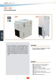
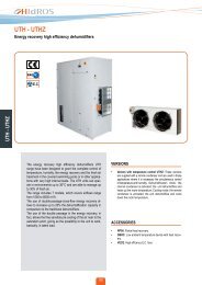
<strong>WDH</strong><br />
LWZ<br />
LPH<br />
High effi ciency air to water heat pumps with E.V.I compressor<br />
High effi ciency air to water heat pumps with E.V.I compressor splitted version<br />
Ground source heat pump<br />
Ground source heat pump<br />
Hybrid high effi ciency air to water heat pumps with E.V.I compressor<br />
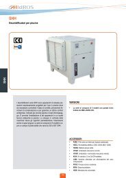
Swimming pool air to water heat pumps<br />
34<br />
40<br />
46<br />
52<br />
60<br />
66<br />
Heat pump systems<br />
Installation description<br />
70<br />
86
The Company<br />
HIDROS<br />
HIDROS was born in 1993 as a trading company involved in the market of dehumidifi cation and humidifi cation of the air.<br />
Quite soon the necessity to satisfy the great demand of special products, in a wide variety of applications and capacities, lead the company<br />
in 2001, to develop and produce its own production.<br />
Today HIDROS with its qualifi ed staff, designs, develops and tests dehumidifying systems and air handling units based on refrigerant<br />
cycle, heat pumps and water chillers.<br />
2
Hidros catalogue includes standard dehumidifi ers with capacities from 25 to 3000 l/24h, heat pumps and water chiller with cooling and<br />
heating capacities from 5 to 900 kW. At this range HIDROS adds a wide range of tailor made machines to meet any customer requirement.<br />
High competence and enthusiasm are the other essential elements that guarantee quick, fl exible and adequate solutions.<br />
HIDROS<br />
Where we are<br />
BOLZANO<br />
BELLUNO<br />
UDINE<br />
TRENTO<br />
PORDENONE<br />
GORIZIA<br />
BRESCIA<br />
VICENZA<br />
VERONA<br />
TREVISO<br />
TRIESTE<br />
PADOVA<br />
VENEZIA<br />
MANTOVA<br />
ROVIGO<br />
From Milan airport:<br />
take the A4 motorway (in the direction to Venice) - leave the motorway at the Padova Est exit<br />
From Bologna airport:<br />
take the A13 motorway (in the direction to Padova), then continue on the A4 (in the direction of Venice) - leave the motorway at the<br />
Padova Est exit<br />
From Venice airport:<br />
take the A4 motorway (in the direction to Milan) - leave the motorway at the Padova Est exit<br />
From Treviso airport:<br />
take the A27 motorway (in the direction to Venice) - at the Venezia-Mestre junction take the A4 motorway (in the direction of Milan) -<br />
leave the motorway at the Padova Est exit<br />
From Verona airport:<br />
take the A4 motorway (in the direction to Venice) - leave the motorway at the Padova Est exit<br />
From the Padova Est exit, to HIDROS:<br />
take the Tangenziale Est (eastern bypass, also called Corso Argentina) and follow the directions for Chioggia, continue along the bypass<br />
for around 5 km until reaching the turnoff at via G. Marconi (Statale Piovese, SS516), follow the directions for Piove di Sacco - continue<br />
for around 12 km, once having passed through the town of Vigorovea, after around 1 km, turn right and follow the directions for Brugine,<br />
after around 800 metres (before the traffi c lights), turn right into Via dell’Industria; HIDROS is on your left at number 5.<br />
3<br />
www.hidros.it
Applications<br />
HIDROS<br />
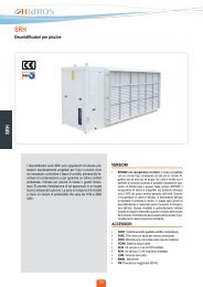
Heat Pump <strong>WDH</strong>/RV in two sections 152-162 model with refrigerant R134a.<br />
Heat Pump air to water model LDKHP 300 SP. Heat Pump air to water model LZT 36.<br />
4
HIDROS<br />
Heat Pump water to water model <strong>WDH</strong> 260. Heat Pump water to water model <strong>WDH</strong>/RV 090.<br />
Heat Pump air to water model LZT 14. Heat Pump air to water model LZH 06.<br />
5<br />
www.hidros.it
WHAT IS A HEAT PUMP?<br />
HIDROS<br />
A heat pump is a device that moves heat<br />
from one location (called the 'source') to<br />
another location (called the 'user'),<br />
using energy.<br />
Basically, a heat pump operates under the<br />
same principles of an air conditioner, but in<br />
the reverse way.<br />
Compressor<br />
Evaporator<br />
Condenser<br />
Expansion device<br />
HOW THE HEAT PUMP WORKS<br />
The heat pump is equipped with a<br />
refrigerant circuit and uses a special fl uid<br />
(called refrigerant fl uid) that, depending on<br />
the temperature and pressure conditions in<br />
which it is working, it can be in gaseous or<br />
liquid state.<br />
The refrigerant circuit is made by:<br />
• The compressor;<br />
• The condenser (also called user heat<br />
exchanger);<br />
• The expansion valve;<br />
•The evaporator (also called source heat<br />
exchanger).<br />
The refrigerant fl uid, in its gaseous state,<br />
is pressurized and circulated through the<br />
system by the compressor.<br />
On the discharge side of the compressor,<br />
the hot and highly pressurized gas is<br />
cooled in a heat exchanger, the condenser,<br />
until it condenses into a high pressure,<br />
moderate temperature liquid. The<br />
condensed refrigerant fl uid then passes<br />
through a pressure-lowering device (the<br />
expansion valve). This device then passes<br />
the low pressure, (almost) liquid refrigerant<br />
to another heat exchanger, the evaporator<br />
where the refrigerant fl uid evaporates into<br />
gas via heat absorption. The refrigerant<br />
then returns to the compressor and the<br />
cycle is repeated.<br />
In such a system it is essential that the<br />
refrigerant fl uid reaches a suffi ciently high<br />
temperature when compressed. Similarly,<br />
the fl uid must reach a suffi ciently low<br />
temperature when allowed to expand and<br />
in particular, the pressure difference must<br />
be great enough for the fl uid to condense<br />
at the hot side and still evaporate in the<br />
lower pressure region at the cold side. The<br />
greater is the temperature difference, the<br />
greater is the required pressure difference,<br />
and consequently more energy is needed<br />
to compress the fl uid.<br />
Thus as with all heat pumps, the energy<br />
effi ciency (amount of heat moved per unit<br />
of input work required) decreases with<br />
increasing temperature difference.<br />
Heat pumps are also available in reversible<br />
versions; this means that during winter<br />
season they produce heating, during<br />
summer period they can produce cooling.<br />
This process is carried out by the use of a<br />
4 way reversing valve; This valve switches<br />
between "heating mode" and "cooling<br />
mode" by an electric signal given via the<br />
unit controls. By switching the valve, the<br />
freon fl ows one way to produce hot water<br />
and changes over via the control signal to<br />
produce chilled water.<br />
6
THE SOURCE, THE USER.<br />
THE SOURCE<br />
The external mean from which the energy is<br />
absorbed is called cold source. In the heat<br />
pump the refrigerant fl uid absorbs heat<br />
from the cold source in the evaporator. The<br />
LZT, WZT and LPH heat pumps use the<br />
ambient air as cold source, that’s why they<br />
are identifi ed as Air-to–water heat pumps.<br />
The WZH and <strong>WDH</strong> heat pumps use water<br />
as cold source and they are identifi ed as<br />
water to water heat pumps.<br />
THE USER<br />
The water to be heated is called user. In<br />
the heat pump the user is the condenser<br />
in which the refrigerant fl uid transfers<br />
(releases) the thermal energy absorbed<br />
from the source. The thermal energy can<br />
be transferred to the building by a heating<br />
system normally using:<br />
Fan coils,<br />
Radiators;<br />
Underfl oor heating systems.<br />
HIDROS<br />
TYPES OF HEAT PUMPS<br />
There are different types of heat pumps, classifi ed by the type of the source; the main types are:<br />
• AIR TO WATER HEAT PUMPS;<br />
• WATER TO WATER HEAT PUMPS;<br />
• GROUND SOURCE HEAT PUMPS;<br />
• HYBRID HEAT PUMPS;<br />
7<br />
www.hidros.it
HIDROS<br />
• AIR TO WATER HEAT PUMPS;<br />
Air is used as the cold source; it has the<br />
advantage of being available at all times; when<br />
the ambient temperature is close and below<br />
0°C, it is necessary to incorporate a defrost<br />
system into the source heat exchanger.<br />
The aspect that should be considered in the air<br />
to water heat pump, infact, is the occurrence<br />
of a problem with ice on the source coil during<br />
those ambient temperatures.<br />
As a fail-safe to this, the heat pump will melt this<br />
ice (defrost cycle) on it's own, but it requires the<br />
switching of the valve to allow the Freon to run<br />
in reverse direction. After successfully melting<br />
the ice that builds up on the outside coils, the<br />
heat pump will then reverse the valve again<br />
and consequentely the refrigerant cycle.The<br />
internal coils are hot,the external ones are cold,<br />
while the heat pumps produce hot water again.<br />
The defrost cycle absorbs energy from the heat<br />
pump, energy that is lost, and not put into the<br />
hot water circuit, temporarily reducing the heat<br />
pumps heating output. In most cases we can<br />
estimate that, in major European countries the<br />
energy lost during defrost cycle may vary from<br />
5 to 13%.<br />
• WATER TO WATER HEAT PUMPS;<br />
Water is used as cold source; this solution<br />
grants the best performances without the<br />
variations caused due to the external climatic<br />
conditions (typical of the air to water heat<br />
pumps); but the water is not always available,<br />
and it requires an additional cost due to the<br />
external hydraulic connections.<br />
8
• GROUND SOURCE HEAT PUMPS;<br />
Cold source is used from the energy stored in<br />
the ground. The thermal energy (cold source)<br />
is "absorbed" from the ground by pipes,<br />
inside which brine, mixed with water glycol,<br />
is circulating. The brine can be fi tted either<br />
vertically a horizzontally, designed to absorb<br />
the max possible energy.<br />
The horizontal pipes are normally buried at<br />
1 or 1,5 meters depth to avoid variations in<br />
the performances due to different ambient<br />
conditions and to keep the advantages of the<br />
solar irradiation. It is normally necessary, in<br />
these executions to have an underground<br />
piping equal to 2-3 times than the ones in the<br />
surface area of the building to be heated.<br />
In case of vertical pipes, they are normally<br />
designed down to 100 meters deep to obtain,<br />
as average, between 4 to 6 kW each one.<br />
The ground source heat pumps have the<br />
advantage of a constant C.O.P. and heating<br />
capacity without the variations caused due<br />
to the external climatic conditions, but they<br />
present also a sensible cost due to the drilling<br />
to be done.<br />
HIDROS<br />
• HYBRID HEAT PUMPS;<br />
In these versions, there are the advantages<br />
of the air to water heat pumps (in terms of<br />
economicity and installation) and also the<br />
higher effi ciencies typical of the water to water<br />
heat pumps.<br />
These units are always working as air to water<br />
units and they are equipped with fi nned coil and<br />
fans.<br />
The units, are also using a second heat<br />
exchanger, water source, that is used in case of<br />
low ambient temperatures (for example below<br />
0°C).<br />
In these conditions, then, using a small water<br />
source or a small ground probe, it is possible<br />
to keep high the C.O.P. of the unit even with<br />
severe ambient conditions. In this way we can<br />
obtain an excellent ratio between costs and<br />
performances.<br />
9<br />
www.hidros.it
HIDROS<br />
EFFICIENCY OF THE HEAT PUMP<br />
During its operation the heat pump:<br />
•“Absorbs” electricity in the compressor;<br />
•“Absorbs” thermal energy from the source<br />
(air or water);<br />
• Releases thermal energy in the user heat<br />
exchanger (water).<br />
value of 3 to 5. This means that for 1 kWh<br />
of electric input energy , the unit will supply<br />
from 3 to 5 kWh of thermal energy to the<br />
user.<br />
The C.O.P. may vary, depending on the<br />
temperature at which the heat is transferred.<br />
The colder is the source temperature, the<br />
lower is the C.O.P.<br />
The main advantage of the heat pump is the<br />
capacity to supply more energy (thermal)<br />
than the one required for its operation<br />
(electrical).<br />
The effi ciency of a heat pump is measured<br />
by the coeffi cient of performance “C.O.P.”<br />
that is the RATIO between the thermal<br />
energy supplied to the user and the electric<br />
input power absorbed by the unit.<br />
The C.O.P. is variable depending on the<br />
type of the heat pump and the working<br />
conditions, and it is generally around a<br />
Input Power<br />
1 kWh<br />
Heating Capacity<br />
4 kWh<br />
WHY USING A HEAT PUMP<br />
The graphic shows what is the use of<br />
energy in a typical north European region<br />
(i.e. Germany):<br />
The national energetic load is divided as<br />
follows:<br />
• 77,8% Heating;<br />
• 10,5% Domestic hot water;<br />
• 6,6% Home appliances;<br />
• 3,7% Cooking;<br />
• 1,4% Lighting.<br />
It is evident how the reduction of the<br />
energy used for heating (is much more<br />
predominant compared to the other uses)<br />
allows a massive reduction of the energy<br />
bill in different countries.<br />
The heat pump is far more effi cient than<br />
any other heat source available in the<br />
market. Where C.O.P’s between 3 and 5,<br />
the energy used compared to a typical gas<br />
or oil system is from 3 to 5 times less.<br />
This means that not only it gives running<br />
saving but also all other benefits which<br />
include:<br />
• Low emission of greenhouse gases like<br />
CO2;<br />
•Use of electricity, available anywhere;<br />
• Use of renewable energies;<br />
• No need of fuels, gas, oil tanks,<br />
chimneys;<br />
• No environmental pollution;<br />
•In case the electricity used by the heat<br />
pump is produced by photovoltaic<br />
panels , we have an ideal system, with<br />
environmental impact of ZERO.<br />
77,8 %<br />
Heating<br />
10,5 %<br />
Domestic hot water<br />
6,6 %<br />
Home appliances<br />
3,7 %<br />
Cooking<br />
1,4 %<br />
Lighting<br />
10
THE USE OF PRIMARY ENERGY<br />
The diagrams below show the use of primary energy by the different heating system available on the market.<br />
167W + 27W<br />
3W<br />
HIDROS<br />
100W<br />
Electric heating<br />
297W<br />
103W<br />
14W<br />
11W<br />
111W<br />
Oil<br />
125W<br />
100W<br />
11W<br />
8W<br />
Natural Gas<br />
119W<br />
111W<br />
100W<br />
57W + 9W<br />
1W<br />
34W<br />
67W<br />
Air to water heat pump<br />
C.O.P. 3<br />
100W<br />
33W<br />
100W<br />
43W + 7W<br />
1W<br />
26W<br />
75W<br />
Water to water heat pump<br />
C.O.P. 4<br />
76W<br />
25W<br />
100W<br />
11<br />
www.hidros.it
The use of heat pumps reduces the use of primary energy compared to other heating systems showing a massive reduction of CO2<br />
emissions;<br />
HIDROS<br />
Heating system<br />
Used primary energy percentage<br />
Electric heating (297%),<br />
Oil (125%),<br />
Natural Gas (120%).<br />
Air to water heat pump (100%).<br />
Water to water heat pump (76%).<br />
• Heat pumps are the heating system of the future; (easy to maintain, efficient, environment respectful);<br />
• The heat pump can be used for heating, cooling and domestic hot water production;<br />
• Because of their efficient performances, many users have already heat pumps, widely used in North Europe<br />
countries<br />
• The price of electricity remain quite stable, on the contrary of the gas. This allows a correct planning of<br />
investment.<br />
• Once installed, the heat pump does not require maintenance.<br />
APPLICATIONS OF THE HEAT PUMPS<br />
The heat pumps are now commonly used both in residential, commercial buildings and in the service industry as an alternative to the<br />
ordinary systems of heating and cooling using boilers and water chillers. As a matter of fact the same unit is able to produce heating in<br />
winter and cooling in summer thanks to a simple valve, which changes the functions of evaporator and condenser (reversible type). The<br />
application of the heat pump for heating and cooling is much more effi cient and the pay back period is shorter compared to a heating only<br />
application. The heat pump, anyway, can also be used for the production of residential heating and of the domestic water only.<br />
DOMESTIC HOT WATER (SW)<br />
HIDROS heat pumps are able to produce hot water up to 55÷63°C(depending on different versions) that allow the installation of the units in<br />
all applications where domestic hot water is required.In this case, it is necessary to use tanks bigger than those used in the normal boilers<br />
since the water temperature stocked doesn’t normally exceed 45-50°C. The average domestic hot water quantities at 45°C are reported<br />
in the following table:<br />
N°User<br />
D.H.W.<br />
(lt/24h)<br />
N°User<br />
D.H.W.<br />
(lt/24h)<br />
N°User<br />
D.H.W.<br />
(lt/24h)<br />
N°User<br />
D.H.W.<br />
(lt/24h)<br />
1 70 2 140 3 190 5 270<br />
12
HOW TO DESIGN A HEAT PUMP<br />
The correct design of the heat pumps is extremely<br />
important in the calculation of the<br />
total effi ciency of the heating system; An<br />
oversized heat pump could create comfort<br />
problems in the room due to wide pendulations<br />
of the hot water (and having a high<br />
economic impact), while an undersized<br />
heat pump could create important reduction<br />
in the effi ciency of the system due to<br />
the necessity of integration with external<br />
sources (like electric heaters or boilers).<br />
It is clear that, an excellent heat pump<br />
combined to a bad heating system brings<br />
anyway to a general bad result, confi rming<br />
then the necessity of a correct combination<br />
heat pump/heating system.<br />
In general, we can assume that, every °C<br />
less in the hot water temperature corresponds<br />
to an average C.O.P. increase of<br />
about 2-2,5% (even higher in the water to<br />
water units) with important consequents in<br />
the effi ciency of the whole system and the<br />
relative energy saving.<br />
The underfl oor heating systems, from this<br />
point of view, are extremely interesting since<br />
they allow the operation in heating with<br />
water temperatures around 30÷38°C, while<br />
radiators or fan coil systems require higher<br />
temperatures (around 50°C) with inevitable<br />
reduction of the general C.O.P.<br />
In line of principle, heat pump systems<br />
are designed with a maximum water outlet<br />
temperature at 55°C. In case higher temperatures<br />
are required (for example, restructiring<br />
of old buildings where it is not possible<br />
to replace the old heating elements), it has<br />
to be considered the integration of the heat<br />
pump with other energy sources (electric<br />
heaters or boilers) especially at low ambient<br />
conditions.<br />
In case of water temperature lower than<br />
55°C, heat pumps normally do not need<br />
integration with other energy sources and<br />
its use is to be taken into consideration only<br />
for economic or fi nancial evaluations that<br />
we will discuss in the next pages.<br />
HIDROS<br />
Some examples:<br />
Heat pump LZT14T @: Ambient temperature: 2°C<br />
Water temperature 35°C C.O.P. 3,8<br />
Water temperature 45°C C.O.P. 3,3<br />
Water temperature 55°C C.O.P. 2,8<br />
Heat pump <strong>WDH</strong> 50 @: Source water temperature: 10°C<br />
Water temperature 35°C C.O.P. 5,3<br />
Water temperature 45°C C.O.P. 4,0<br />
Water temperature 55°C C.O.P. 3,1<br />
Today, the main solutions with heat pumps available on the market are:<br />
• Monovalent systems;<br />
• Monovalent systems with electric integration;<br />
• Bivalent systems.<br />
In this issue, we will not talk about bivalent systems (which include the use of other energetic sources besides the electric one) and we<br />
will focus on the 2 fi rst systems:<br />
13<br />
www.hidros.it
HIDROS<br />
MONOVALENT SYSTEMS<br />
In general, with monovalent systems are intended those applications where it is not necessary to integrate the heating capacity produced<br />
by the unit. The heat pump supplies the 100% of the heating capacity required by the building.<br />
The design of the heat pumps in the monovalent systems is done by taking the heating capacity of the unit in the minimum ambient<br />
conditions.<br />
Example:<br />
Location: Stuttgart (Germany)<br />
This location has the following climatic trend (see below graphic):<br />
Ore<br />
600<br />
500<br />
400<br />
300<br />
200<br />
100<br />
0<br />
-30 -25 -20 -15 -10 -5 0 5 10 15 20 25 30 35 40<br />
(°C)<br />
Ambient temperature °C -30 -29 -28 -27 -26 -25 -24 -23 -22 -21 -20 -19 -18 -17 -16 -15 -14 -13 -12 -11 -10<br />
Hours/Year 0 0 0 0 0 0 0 0 0 0 0 0 0 0 0 0 6 12 11 11 24<br />
Ambient temperature °C -9 -8 -7 -6 -5 -4 -3 -2 -1 0 1 2 3 4 5 6 7 8 9 10 11<br />
Hours/Year 20 38 27 29 45 74 141 171 214 338 426 421 329 395 430 332 345 343 345 353 366<br />
Ambient temperature °C 12 13 14 15 16 17 18 19 20 21 22 23 24 25 26 27 28 29 30 31 32<br />
Hours/Year 368 437 400 382 350 345 279 215 197 146 111 97 61 50 34 17 12 6 4 3 0<br />
Ambient temperature °C 33 34 35 36 37 38 39 40<br />
Hours/Year 0 0 0 0 0 0 0 0<br />
From the graphic it is evident that the location has a minimum ambient temperature of -14°C for 6 hours per year. In case we have a<br />
building which has a heat loss of 9 kw at -5°C ambient, with an indoor temperature of 20°C, located in Stuttgart, we will have a heat loss<br />
(calculated in accordance to UNI12813*) represented by the following table.<br />
* Refer always to the load laws in force in the country in which the heat pump is installed.<br />
14
SOLUTION WITH GROUND SOURCE HEAT PUMP<br />
The main characteristic of the ground source and/or water to water heat pumps is the one of keeping constant the heating capacity and<br />
the C.O.P. at different ambient conditions; this aspect allows an optimal unit sizing which allows costant and high C.O.P., since it’s not<br />
infl uenced by the external temperature.<br />
20<br />
(kW)<br />
HIDROS<br />
15<br />
Heating capacity WZH09<br />
10<br />
5<br />
Building Heat Loss<br />
0<br />
-30 -25 -20 -15 -10 -5 0 5 10 15 20 25 30 35 40<br />
(°C)<br />
In this case, the ground source heat pump which satispies the required capacity is the model WZH09. It has a heating capacity of 12,9<br />
kw with source water temperature 0°C and user water outlet 35°C.<br />
SOLUTION WITH AIR TO WATER HEAT PUMP LZT SERIES<br />
If we install, in the same building, an air to water heat pump (LZT or WZT series), the trend of the heating capacity becomes the following:<br />
(kW)<br />
35<br />
Ambient temperature: Heat Loss Heating capacity WZH09<br />
0°C 7 kW 12,2 kW<br />
-5°C 9 kW 12,2 kW<br />
-14°C 12,2 kW 12,2 kW<br />
30<br />
25<br />
Heating capacity LZT 21<br />
20<br />
15<br />
10<br />
Building Heat Loss<br />
5<br />
0<br />
-30 -25 -20 -15 -10 -5 0 5 10 15 20 25 30 35 40<br />
(°C)<br />
Ambient temperature: User Heat Loss Heating capacity LZT21<br />
0°C 35°C 7 kW 17,8 kW<br />
-5°C 35°C 9 kW 16,0 kW<br />
-14°C 35°C 12,2 kW 12,9 kW<br />
15<br />
www.hidros.it
HIDROS<br />
In this case, if we intend to use a monovalent<br />
system, we should select an LZT21<br />
that, at -14°C ambient temperature, produces<br />
a heating capacity of 12,9 kW.<br />
The selection of the LZT21, anyway, even<br />
being technically correct, is not economically<br />
and energetically interesting, since it<br />
involves an OVERSIZED unit, clearly too<br />
big for the remaining period of the year.<br />
The use of the LZT21, also involves a bigger<br />
water pump, bigger pipe diameters and<br />
the unit could result noisy and having not<br />
compatible dimensions.<br />
The above example shows the main difference<br />
between a ground source heat pump<br />
and an air to water heat pump; it consists<br />
on the different heating capacity when the<br />
ambient temperature varies.<br />
While the ground source heat pump (or water<br />
to water) has a constant source temperature<br />
and a consequent constant heating<br />
capacity, the air to water heat pump shows<br />
a decisive variation of the heating capacity<br />
when the ambient temperature varies.<br />
This characteristic could have negative<br />
infl uence if the unit is installed in locations<br />
with severe ambient conditions (very cold)<br />
while could be positive if the unit is installed<br />
in warmer locations, where the use of an<br />
air to water heat pump instead of a ground<br />
source one, should be more effi cient.<br />
Generally speaking, in a the installations<br />
with air to water heat pumps, it is not used a<br />
monovalent system but it is preferred a monovalent<br />
system with electric integration.<br />
MONOVALENT SYSTEMS WITH ELECTRIC INTEGRATION<br />
Normally, it’s considered a monovalent system<br />
with electric integration a plant where<br />
the heating capacity generated by the heat<br />
pump is supported, for short periods, by<br />
electric heaters.<br />
In this case the heat pump supplies just a<br />
part of the heating capacity required by the<br />
building, a value that, to obtain a good compromise<br />
costs/benefi ts, it is normally calculated<br />
in a way that the unit should be able<br />
to satisfy the building heat loss for 90-95%<br />
of the time of winter season.<br />
The design of the heat pumps in the monovalent<br />
systems with electric integration is<br />
done excluding the minimum ambient temperatures<br />
present for 5% to 10% of the time<br />
of the winter season.<br />
Specifi cally, the selected location shows<br />
the following diagram:<br />
Ambient temperature: N°hours year: Winter season<br />
-14°C a 20°C 8219 Total winter season<br />
-14°C a +5°C 3162 38,4%<br />
-14 a 0°C 1161 14,0%<br />
-14 a -5°C 223 2,70%<br />
-14 a -10°C 64 0,77%<br />
-14°C 6 0.07%<br />
If we consider the possibility of using an air<br />
to water heat pump in the same building of<br />
the previous example we will proceed in the<br />
following way:<br />
A minimum ambient temperature, to which<br />
the heat pump can satisfy, by the building<br />
has to be established.<br />
This because the period of time during<br />
which the heat pump will be undersized can<br />
not be more than 5/10 %.<br />
The below graphic shows that the ambient<br />
temperature “goes” from -14°C (minimum<br />
winter ambient temperature) to -5°C,<br />
during a period of time of 223 hours per<br />
year, corresponding of 2,7% of the total<br />
winter season.<br />
In the same way, we can see that the<br />
location shows an ambient temperature<br />
below 0°C for 1161 hours, equivalent to the<br />
14% of the total winter season.<br />
If we report in the below diagram the heating<br />
capacities of the sizes LZT10T, 14T and 21,<br />
we can notice the following trends:<br />
16
(kW)<br />
35<br />
30<br />
25<br />
Heating capacity LZT21<br />
HIDROS<br />
20<br />
15<br />
Heating capacity LZT14T<br />
10<br />
Heating capacity LZT10T<br />
5<br />
Building Heat Loss<br />
0<br />
-30 -25 -20 -15 -10 -5 0 5 10 15 20 25 30 35 40<br />
(°C)<br />
The intersection point between the segments identify the minimum ambient temperature at which the selected heat pump is able to satisfy<br />
the heat loss of the building; It's necessary to integrate the heating capacity of the heat pump with electric heaters with lower ambient<br />
temperatures.<br />
Using a Heat Pump:<br />
Using an LZT21 the balance point will be at -14°C;<br />
Using an LZT14T the balance point will be at -8°C;<br />
Using an LZT10T the balance point will be at -2°C;<br />
The correct selection, in this case, will be the LZT14T that, with a balance point of -8°C, shows the best compromise between costs and<br />
benefits.<br />
17<br />
www.hidros.it
HIDROS<br />
SELECTION SOFTWARE<br />
For a right selection of the heat pump, Hidros has developed and makes available to installers a sofi sticated software which permits to<br />
calculate all the parameters of the system:<br />
• Intersection point heat pump/installation;<br />
• Season thermal energy produced by the heat pump;<br />
• Calculation of the thermic power for the hot domestic water;<br />
• Energy losses for thefrosting (only air to water heat pump);<br />
Project reference:<br />
Reference location:<br />
Building heat loss @ -5°C<br />
Number of persons<br />
Heat pump kWh electric cost<br />
Integration electric heater kWh cost<br />
Heat pump model:<br />
HEAT PUMP SEASON EFFICIENCY SIMULATION<br />
Heat pump type<br />
Hidros srl<br />
Sede legale: via della Croce Rossa 32/2 35129 (Pd) Italy<br />
Sede operativa: via dell’industria 5, 35020 Brugine (Pd) Italy<br />
VAT IT 03598340283 Codice fiscale 03598340283<br />
Tel. +39 049 9731022 Fax. +39 049 5806928<br />
Web:www.hidros.it E-mail: info@hidros.it<br />
Germany - Stuttgart<br />
Indoor temperature<br />
°C<br />
kW 9,0 Source inlet temperature (Dt=3°C) °C<br />
n. 4 Hot water temperature<br />
°C<br />
€/kWh 0,11 Ambient temperature with off installation ≥°C<br />
€/kWh 0,11 Domestic hot water quantity per person l<br />
Domestic hot water temperature<br />
LZT14T 400/3<br />
°C<br />
Domestic water inlet temperature °C<br />
√<br />
Air/Water<br />
Water/Water<br />
Ground source<br />
20<br />
…<br />
35<br />
16<br />
50<br />
50<br />
10<br />
BUILDING HEAT LOSS / HEATING PRODUCED BY THE HEAT PUMP<br />
The graphic shows the building energy loss (in kwh including DHW energy - red line), compared to the heating capacity developed by the heat<br />
pump (in kwh- black line). The graphic includes the heat loss of the heat pump due to the defrost cycle.<br />
(kWh)<br />
3500<br />
3000<br />
2500<br />
2000<br />
1500<br />
1000<br />
500<br />
0<br />
-30 -25 -20 -15 -10 -5 0 5 10 15 20 25 30 35 40<br />
(°C)<br />
AMBIENT TEMPERATURE TREND<br />
In the table it's underlined the number of hours / year of the selected location, in relation to the ambient temperature (Dry Bulb).<br />
Ambient temperature (°C)<br />
Hours (h)<br />
Ambient temperature (°C)<br />
Hours (h)<br />
Ambient temperature (°C)<br />
Hours (h)<br />
Ambient temperature (°C)<br />
Hours (h)<br />
Ambient temperature (°C)<br />
Hours (h)<br />
-30 -29 -28 -27 -26 -25 -24 -23 -22 -21 -20 -19 -18 -17 -16 -15<br />
0 0 0 0 0 0 0 0 0 0 0 0 0 0 0 0<br />
-14 -13 -12 -11 -10 -9 -8 -7 -6 -5 -4 -3 -2 -1 0 1<br />
6 12 11 11 24 20 38 27 29 45 74 141 171 214 338 426<br />
2 3 4 5 6 7 8 9 10 11 12 13 14 15 16 17<br />
421 329 395 430 332 345 343 345 353 366 368 437 400 382 350 345<br />
18 19 20 21 22 23 24 25 26 27 28 29 30 31 32 33<br />
279 215 197 146 111 97 61 50 34 17 12 6 4 3 0 0<br />
34 35 36 37 38 39 40<br />
0 0 0 0 0 0 0<br />
Total hours 8760<br />
18
• Electric energy with integrations;<br />
• Operating costs;<br />
• Installation season C.O.P..<br />
Please contact the company for the availability of the software.<br />
HIDROS<br />
HEAT PUMP SEASON EFFICIENCY SIMULATION<br />
Hidros srl<br />
Sede legale: via della Croce Rossa 32/2 35129 (Pd) Italy<br />
Sede operativa: via dell’industria 5, 35020 Brugine (Pd) Italy<br />
VAT IT 03598340283 Codice fiscale 03598340283<br />
Tel. +39 049 9731022 Fax. +39 049 5806928<br />
Web:www.hidros.it E-mail: info@hidros.it<br />
Building heat loss<br />
Building heat loss + DHW<br />
Domestic hot water request (DHW)<br />
Seasonal energy produced by the HP<br />
Seasonal heat pump input energy<br />
Integration electric energy<br />
Integration electric power<br />
kwh 34530 Total winter season<br />
h 7183<br />
kwh 37925 Heat pump hours operation<br />
h 3303<br />
kwh 3395 Heat loss due to defrost cycle<br />
kw 6226<br />
kWh 35850 Heat loss due to defrost cycle<br />
% 16,8%<br />
kwh 11343 Electric energy cost of the heat pump € 1247,7<br />
kwh 1464 Integration electric energy cost<br />
€ 161,0<br />
kw 3,2 Total seasonal electric energy cost € 1408,7<br />
Seasonal heat pump<br />
efficiency<br />
C.O.P.<br />
3,2<br />
Seasonal heat pump efficiency +<br />
integration heating<br />
C.O.P.<br />
2,9<br />
AMBIENT TEMPERATURE TREND<br />
In the graphic it's underlined the number of hours / year of the selected location, in relation to the ambient temperature (Dry Bulb).<br />
400<br />
300<br />
h<br />
200<br />
100<br />
(°C)<br />
0<br />
-30 -25 -20 -15 -10 -5 0 5 10 15 20 25 30 35 40<br />
BALANCE POINT<br />
The graphic shows the balance point between the power building heat loss + DHW and the heating capacity produced by the HP.<br />
kW<br />
40,0<br />
30,0<br />
20,0<br />
10,0<br />
(°C)<br />
0,0<br />
-30 -25 -20 -15 -10 -5 0 5 10 15 20<br />
19<br />
www.hidros.it
WHAT IS THE E.V.I. TECHNOLOGY<br />
HIDROS<br />
HIDROS LZT and WZT heat pump units<br />
starting from model 10 are supplied<br />
with compressors equipped with E.V.I.<br />
technology, a versatile method of improving<br />
system capacity and effi ciency. The vapour<br />
injection technology consists of injecting<br />
refrigerant vapour in the middle of the<br />
compression process, to boost capacities<br />
and effi ciencies signifi cantly. Each scroll<br />
compressor used in the LZT and WZT units<br />
is similar to a two-stage compressor but<br />
with built-in interstage cooling. In the above<br />
diagram are shown the main phases of the<br />
refrigerant cycle in a E.V.I. unit.<br />
P<br />
Pi<br />
Pm<br />
i<br />
m+i<br />
h<br />
Compressor<br />
i<br />
Injection<br />
Condenser<br />
m + i<br />
Expansion<br />
valve<br />
Evaporator<br />
m<br />
The high stage consists of extracting<br />
a portion of the condenser liquid and<br />
expanding it through an expansion valve<br />
into a heat exchanger acting as a sub<br />
cooler. The superheated vapour is then<br />
injected into an intermediate part in the<br />
scroll compressor.<br />
The additional sub cooling increases the<br />
evaporator capacity. The bigger it's the<br />
pressure ratio between condensing and<br />
evaporating pressures, the more signifi cant<br />
is the performance compared to any other<br />
compressor technology. This technology<br />
allows the LZT and WZT units to produce<br />
hot water up to 63°C with the possibility<br />
to operate down to -15°C ambient<br />
temperature.<br />
20
The graphics below show the trend of the coeffi cient of performance C.O.P. in 2 conditions: hot water production at 40°C and 55°C. The<br />
lines show different types of scroll compressors today available on the market also using different refrigerant gases: R407C, R410a. It is<br />
evident that the working range of R407C is wider than R410A ones, especially in case of low ambient conditions.<br />
C.O.P<br />
5<br />
Water produce at 40°C<br />
C.O.P<br />
4<br />
Water produce at 55°C<br />
HIDROS<br />
4,5<br />
3,5<br />
4<br />
3<br />
3,5<br />
3<br />
2,5<br />
2,5<br />
2<br />
2<br />
-20 -15 -10 -5 0 5 10<br />
Ambient temperature (°C)<br />
The effi ciency of the EVI compressors at<br />
low ambient conditions is about 25% higher<br />
than the standard scroll compressors;<br />
Such differences become even much more<br />
evident in applications with quite high hot<br />
water temperatures (i.e. when domestic<br />
hot water is required). In this case we<br />
can also notice that the operational limits<br />
of a standard scroll compressor are not<br />
suffi cient to produce the required hot<br />
water temperature (55°C) at ambient<br />
temperatures below 5°C.<br />
1,5<br />
-20 -15 -10 -5 0 5 10<br />
Ambient temperature (°C)<br />
The below graphic shows the operation<br />
range of the EVI scroll compressors supplied<br />
in the LZT and WZT units; at -15°C ambient<br />
the water outlet temperature is still 55°C;<br />
this allows the heat pump to be installed in<br />
much more diverse ambient conditions.<br />
Water Temperature °C<br />
65<br />
60<br />
55<br />
50<br />
45<br />
40<br />
35<br />
30<br />
25<br />
20<br />
-20 -15 -10 -5 0 5 10 15 20 25 30<br />
Ambient temperature (°C)<br />
Units equipped with scroll compressors<br />
with vapour injection technology E.V.I. with<br />
freon R407C.<br />
Units equipped with scroll compressors<br />
HP (high performance) without the vapour<br />
injection system E.V.I. freon R407C.<br />
Units equipped with standard scroll<br />
compressors with freon R407C.<br />
Units equipped with standard scroll<br />
compressors with freon R410A.<br />
21<br />
www.hidros.it
LZT<br />
High efficiency air to water heat pumps with E.V.I.<br />
compressors<br />
LZT<br />
-15°C<br />
+63°C<br />
E.V.I.<br />
C.O.P.≥4,1<br />
The high effi ciency LZT heat pump series have been<br />
especially designed for application with radiant fl oor heating<br />
systems or in those applications where it is necessary to<br />
have the highest maximum effi ciency in heating mode. The<br />
units have been optimized for heating mode, they are able<br />
to produce water up to 63°C and they can operate down to<br />
-15°C ambient temperature.<br />
The LZT units are available in the 2 pipes version and in the<br />
SW6 version, with 4 pipes.<br />
Both the versions can produce domestic hot water; the LZT<br />
through the activation of an external 3-way-valve, the SW6<br />
one, through a suitable hydraulic circuit for the domestic hot<br />
water which allows its production independently from the unit<br />
version.<br />
All models are supplied standard with reverse cycle valve for<br />
cold water production.<br />
OTHER VERSION<br />
• LZT 2 pipes reversible standard.<br />
• LZT/SW6 4 pipes unit able to produce hot and cold<br />
water at the same time on two independent hydraulic<br />
circuits.<br />
ACCESSORIES<br />
•<br />
•<br />
•<br />
•<br />
•<br />
•<br />
•<br />
•<br />
•<br />
LS low noise version.<br />
Pumps contacts (user pump, domestic hot water<br />
pump).<br />
Electronic soft starter.<br />
Rubber vibration dampers.<br />
Spring vibration dampers.<br />
Refrigerant pressure gauges.<br />
Remote control panel.<br />
Serial interface card RS 485.<br />
condensate discharge drip tray with antifreeze heater.<br />
22
LZT<br />
Model LZT - LZT/SW6 10M 10T 14M 14T 21 26<br />
Heating capacity (EN14511) (1) kW 9,6 9,6 13,9 13,9 19,6 26,5<br />
Total input power (EN14511) (1) kW 2,3 2,3 3,4 3,2 4,5 6,4<br />
COP (EN14511) (1) W/W 4,2 4,2 4,1 4,3 4,4 4,1<br />
Heating capacity (EN14511) (2) kW 9,5 9,4 14,0 13,9 19,1 26,4<br />
Total input power (EN14511) (2) kW 2,7 2,7 4,0 3,8 5,3 7,7<br />
COP (EN14511) (2) W/W 3,5 3,5 3,5 3,7 3,6 3,4<br />
Heating capacity (EN14511) (3) kW 6,8 6,7 10,0 10,0 14,2 18,8<br />
Total input power (EN14511) (3) kW 2,1 2,0 3,1 3,0 4,1 6,0<br />
COP (EN14511) (3) W/W 3,2 3,4 3,2 3,3 3,5 3,1<br />
Cooling capacity (EN14511) (4) kW 11,3 11,3 15,4 15,5 21,4 30,9<br />
Total input power (EN14511) (4) kW 3,0 3,0 4,1 4,0 5,6 8,1<br />
EER (EN14511) (4) W/W 3,8 3,8 3,8 3,9 3,8 3,8<br />
Cooling capacity (EN14511) (5) kW 8,6 8,9 11,7 11,8 16,5 22,2<br />
Total input power (EN14511) (5) kW 2,6 2,5 3,7 3,6 5,0 7,5<br />
EER (EN14511) (5) W/W 3,3 3,6 3,2 3,3 3,3 3,0<br />
Power supply V/Ph/Hz 230/1/50 400/3+N/50 230/1/50 400/3+N/50<br />
Max input current A 25,5 8,0 33,0 12,0 19,5 22,0<br />
Peak current A 100,0 45,0 162,0 60,0 106,0 101,0<br />
Fans n° 1 1 2 2 2 2<br />
Compressors n°/tipo 1/Scroll with EVI<br />
Sound power level (6) dB (A) 69 69 71 71 75 79<br />
Sound pressure level (7) dB (A) 41 41 43 43 47 51<br />
Water pump (optional) kW 0,2 0,2 0,3 0,3 0,45 0,55<br />
Water tank (optional) l 40 40 60 60 60 180<br />
LZT<br />
Model LZT - LZT/SW6 36 46 52 72 82 92<br />
Heating capacity (EN14511) (1) kW 37,4 44,7 52,0 74,8 89,4 106,4<br />
Total input power (EN14511) (1) kW 8,4 10,0 11,8 18,1 22,0 26,2<br />
COP (EN14511) (1) W/W 4,5 4,5 4,5 4,1 4,1 4,1<br />
Heating capacity (EN14511) (2) kW 36,4 45,1 52,2 72,3 90,2 106,1<br />
Total input power (EN14511) (2) kW 10,0 12,2 14,4 21,1 26,5 30,2<br />
COP (EN14511) (2) W/W 3,6 3,7 3,6 3,4 3,4 3,5<br />
Heating capacity (EN14511) (3) kW 25,7 32,2 37,0 50,5 64,6 75,1<br />
Total input power (EN14511) (3) kW 7,5 9,1 10,7 16,4 20,4 23,9<br />
COP (EN14511) (3) W/W 3,4 3,5 3,5 3,1 3,2 3,1<br />
Cooling capacity (EN14511) (4) kW 42,2 46,6 57,8 84,4 93,2 117,0<br />
Total input power (EN14511) (4) kW 10,8 12,5 15,2 23,6 27,0 33,2<br />
EER (EN14511) (4) W/W 3,9 3,7 3,8 3,6 3,5 3,5<br />
Cooling capacity (EN14511) (5) kW 30,9 37,3 42,8 61,0 74,6 89,0<br />
Total input power (EN14511) (5) kW 9,7 12,0 13,4 21,3 26,0 30,8<br />
EER (EN14511) (5) W/W 3,2 3,1 3,2 2,9 2,9 2,9<br />
Power supply V/Ph/Hz 400/3+N/50<br />
Max input current A 26,0 31,1 39,7 50,0 58,0 71,2<br />
Peak current A 129,0 170,0 121,0 155,0 199,0 237,0<br />
Fans n° 2 2 2 2 2 2<br />
Compressors n°/tipo 1/Scroll with EVI 2/Scroll with EVI<br />
Sound power level (6) dB (A) 79 79 82 82 82 83<br />
Sound pressure level (7) dB (A) 51 51 54 54 54 55<br />
Water pump (optional) kW 0,55 1,0 1,3 1,3 1,5 1,5<br />
Water tank (optional) l 180 300 300 300 300 300<br />
Performance refer to the following conditions:<br />
(1) Heating: Ambient temperature 7°C DB, 6°C WB, water temperature 35/30°C. (2) Heating: Ambient temperature 7°C DB, 6°C WB, water temperature 45/40°C.<br />
(3) Heating: Ambient temperature -7°C DB, -8°C WB, water temperature 35/30°C. (4) Cooling: ambient temperature 35°C, water temperature 23/18°C.<br />
(5) Cooling: ambient temperature 35°C, water temperature 12/7°C. (6) Sound power level according to ISO 3746 (LS version).<br />
(7) Sound pressure level at 10 mt from the unit in free fi eld conditions direction factor Q=2, according<br />
to ISO 3746 (LS version).<br />
23<br />
www.hidros.it
LZT<br />
LZT<br />
FRAME<br />
All LZT units are made from hot-galvanised<br />
thick sheet metal, painted with polyurethane<br />
powder enamel at 180°C to ensure the<br />
best resistance against the atmospheric<br />
agents. The frame is self-supporting<br />
REFRIGERANT CIRCUIT<br />
The refrigerant gas used in these units is<br />
R407C. The refrigerant circuit is made by<br />
using international primary brands components<br />
and according to ISO 97/23 concerning<br />
welding procedures. The refrigerant<br />
circuit includes:<br />
sight glass, fi lter drier, double thermal expansion<br />
valves (one for cooling mode, one<br />
for heating mode) with external equalizer,<br />
4 way reverse cycle valve, one way valves,<br />
liquid receiver, Schrader valves for<br />
maintenance and control, pressure safety<br />
device (according to PED regulation). Models<br />
starting from 10 are also supplied with<br />
an AISI316 stainless steel heat exchanger<br />
used as economizer and additional expansion<br />
valve for refrigerant vapour injection.<br />
COMPRESSORS<br />
The compressors used are high performance<br />
scroll type, supplied with a special scroll<br />
design which enhances the effi ciency of the<br />
refrigerant cycle at low ambient conditions.<br />
Starting from size 52, the compressors are<br />
in tandem execution. Units starting from<br />
model 10 are also supplied with economizer<br />
and vapour injection system, a versatile<br />
method of improving system capacity and<br />
effi ciency. The vapour injection technology,<br />
consists of injecting refrigerant vapour in<br />
the middle of the compression process, to<br />
boost capacities and effi ciencies signifi cantly.<br />
Each scroll compressor used in the LZT<br />
units is basically similar to a two-stage compressor<br />
but with built-in interstage cooling.<br />
The highest stage consists of extracting a<br />
portion of the condenser liquid and expanding<br />
it through an expansion valve into a<br />
heat exchanger acting as a sub cooler. The<br />
superheated vapour is then injected into<br />
an intermediate port in the scroll compressor.<br />
The additional sub cooling increases<br />
the evaporator capacity. The bigger is the<br />
pressure ratio between condensing and<br />
evaporating pressures, the more signifi cant<br />
the performance gains with this system<br />
compared to any other compressor tech-<br />
nology. The compressors are all supplied<br />
with crankcase heater and thermal overload<br />
protection by a klixon embedded in<br />
the motor winding. They are mounted in a<br />
separate chamber in order to be separated<br />
from the air stream. The crankcase heater<br />
is always powered when the compressor<br />
is in stand-by. The inspection is possible<br />
through the frontal panel of the unit that allows<br />
the maintenance of the compressors<br />
even if the unit is working.<br />
SOURCE HEAT EXCHANGER<br />
The source heat exchangers are made of<br />
copper pipes and aluminium fi ns. The diameter<br />
of the copper pipes is 3/8” and the<br />
thickness of the aluminium fi ns is 0,1 mm.<br />
The tubes are mechanically expanded into<br />
the aluminium fi ns to improve the heat exchange<br />
factor. The geometry of these condensers<br />
guarantees a low air side pressure<br />
drop and then the use of low rotation (and<br />
low noise emission) fans. The source heat<br />
exchangers can be protected by a metallic<br />
fi lter to be installed on request.<br />
USER HEAT EXCHANGERS<br />
The user heat exchangers are made of AISI<br />
316 stainless steel braze-welded plates<br />
type. The use of this kind of heat exchangers<br />
allows a massive reduction of the refrigerant<br />
charge of the unit compared to the<br />
traditional shell-in-tube evaporators and<br />
also a reduction of the overall dimensions<br />
of the unit. The user heat exchangers are<br />
factory insulated with fl exible close cell material<br />
and can be equipped with antifreeze<br />
heater (optional). Each heat exchanger is<br />
provided with a temperature sensor as antifreeze<br />
protection.<br />
FANS<br />
The fans are axial type with aluminium aerofoil<br />
blades. They are statically and dynamically<br />
balanced and supplied complete of<br />
the safety fan guard according to EN 60335.<br />
They are mounted on the unit frame by interposition<br />
of rubber vibration dampers. The<br />
electric motors are all at 6 poles (about 900<br />
rpm). The motors are directly driven with an<br />
integrated thermal overload protection. The<br />
protection class of the motors is IP 54.<br />
MICROPROCESSORS<br />
All LZT units are supplied standard with microprocessor<br />
controls. The microprocessor<br />
controls the following functions: regulation<br />
of the water temperature, antifreeze protection,<br />
compressor timing, compressor<br />
automatic starting sequence (if more than<br />
one compressor is present), alarm reset.<br />
The control panel is supplied with display<br />
showing all operational icons. The microprocessor<br />
is set for automatic defrost (in<br />
case of operation in severe ambient conditions)<br />
and for summer/winter change over.<br />
The control is also able to manage the program<br />
of thermic shock against legionella,<br />
integration with other thermic sources (electric<br />
heaters), solar panels etc, control and<br />
management of a modulating valve and, of<br />
the domestic circuit pump. Upon request<br />
any microprocessor can be connected to<br />
a BMS system for the remote control and<br />
management. The technical department is<br />
available to study, together with the customer,<br />
different solutions using MODBUS.<br />
ELECTRIC BOX<br />
The electric box is made according to electromagnetic<br />
compatibility norms CEE 73/23<br />
and 89/336. The accessibility to the board is<br />
possible after removing the front panel of the<br />
unit. In all LZT units is installed, standard,<br />
the compressors sequence relay which disables<br />
the operation of the compressor in<br />
case the power supply phase sequence is<br />
not the correct one (scroll compressors in<br />
fact, can be damaged if they rotate reverse<br />
wise). The following components are also<br />
standard installed: main switch, magneticthermal<br />
switches (as a protection of pumps<br />
and fans), compressors fuses, control circuit<br />
automatic breakers, compressor contactors,<br />
fan contactors, pump contactors.<br />
The terminal board is supplied with voltage<br />
free contacts for remote ON-OFF , winter/<br />
summer change over and general alarm.<br />
CONTROL AND PROTECTION DEVICES<br />
All units are supplied with the following<br />
control and protection devices: Return user<br />
water temperature sensor, antifreeze protection<br />
sensor installed on the user outlet<br />
water temperature, return and supply, high<br />
pressure switch with manual reset, low<br />
pressure switch with automatic reset, high<br />
pressure safety valve, compressor thermal<br />
overload protection, fans thermal overload<br />
24
LZT<br />
protection, pressure transducer (used to<br />
optimize the defrost cycle and the fan speed<br />
depending on the ambient conditions),<br />
fl ow switch.<br />
OTHER VERSIONS<br />
LZT/SW6 UNIT WITH INDEPENDENT<br />
DOMESTIC HOT WATER PRODUCTION<br />
This version is suitable to produce<br />
domestic hot water: the unit is supplied<br />
with an additional heat exchanger used as<br />
condenser for the domestic hot water which,<br />
is independent from the operation mode of<br />
the unit. The activation of the additional<br />
heat exchanger is done automatically by the<br />
microprocessor control when the domestic<br />
hot water temperature measured by the<br />
sensor is lower than the required set point.<br />
This unit allows the production of cold and<br />
hot water at the same time independently.<br />
This version is supplied with return/supplied<br />
domestic hot water sensors and advanced<br />
control panel with specifi c software able to<br />
manage the operation<br />
priorities.<br />
VERSIONS<br />
LZT / A1 HIGH EFFICIENCY HEAT PUMP<br />
WITH INTEGRATED HYDRAULIC KIT<br />
The LZT heat pumps can be delivered<br />
as option, with a built in hydraulic kit that<br />
includes:<br />
Water tank in different sizes (depending on<br />
the size of the unit), factory insulated with<br />
fl exible close cell material and prepared<br />
for the installation of antifreeze kit (option).<br />
The water tank is installed on the hot water<br />
outlet water side to minimize the inevitable<br />
fl uctuations in the water temperature due to<br />
the compressors starts and stops.<br />
Water pump, centrifugal type, suitable<br />
for chilled water operation. The pump is<br />
directly controlled by the microprocessor<br />
that controls its correct operation. In the<br />
hydraulic circuit are also present the<br />
expansion vessel, the safety valve and the<br />
eventual manual valves with fi ttings.<br />
LZT/LS LOW NOISE VERSION<br />
This version includes the complete<br />
acoustic insulation of the unit (compressor<br />
+ heat exchangers vanes) with compressor<br />
jackets and insulating material made with<br />
high density media and the interposition of<br />
heavy bitumen layer.<br />
OPERATION LIMITS<br />
LZT<br />
65<br />
60<br />
55<br />
Water temperature production(°C).<br />
50<br />
45<br />
40<br />
35<br />
30<br />
25<br />
20<br />
-20 -15 -10 -5 0 5 10 15 20 25 30<br />
Ambient air temperature (°C).<br />
LZT 2 PIPES VERSION.<br />
LZT/SW6 4 PIPES VERSION.<br />
25<br />
www.hidros.it
LZT<br />
LZT<br />
Versions LZT - LZT/SW6 Codice 10M 10T 14M 14T 21 26<br />
Main switch<br />
Compressor automatic switch<br />
Flow switch<br />
Evap/condens pressure control by transducer and fan speed control<br />
Fresh air temperature probe for set-point compensation<br />
Specifi c software for operation priorities<br />
Remote ON/OFF digital input<br />
Summer/Winter digital input<br />
A1 Hydraulic kit (tank and pump)<br />
A1ZZ<br />
A2 Hydraulic kit (tank and 2 pumps) A2ZZ – – – – – –<br />
A1NT Hydraulic kit (pump only)<br />
A1NT<br />
A2NT Hydraulic kit (2 pumps only) A2NT – – – – – –<br />
A0NP Hydraulic kit (with tank, without pump) AONP – – – – – –<br />
LS Low noise version<br />
LS00<br />
Rubber vibration dampers<br />
KAVG<br />
Evaporator antifreeze heater (basic version only)<br />
RAEV<br />
Antifreeze kit (only for A versions)<br />
RAES<br />
Integrative electric heater kit<br />
RIAO<br />
Refrigerant pressure gauges<br />
MAML<br />
Electronic Soft starter<br />
DSSE<br />
Remote control panel<br />
PCRL<br />
Condensate discharge drip tray with antifreeze heater<br />
BRCA<br />
Coil protection mesh with metallic fi lter FAMM – – – – –<br />
Serial interface card RS485 with MODBUS protocol<br />
INSE<br />
Standard, Optional, – Not available.<br />
LZT 10M÷10T LZT 14÷21<br />
Mod. A (mm) B (mm) C (mm) Kg<br />
06/06A1 989 1103 380 95/148<br />
08/08A1 989 1103 380 104/163<br />
10M/10MA1 989 1103 380 118/179<br />
10T/10TA1 989 1103 380 120/181<br />
Mod. A (mm) B (mm) C (mm) Kg<br />
14M/14MA1 1323 1203 423 127/207<br />
14T/14TA1 1323 1203 423 133/212<br />
21/21A1 1424 1453 473 390/550<br />
26
LZT<br />
Versions LZT - LZT/SW6 Codice 36 46 52 72 82 92<br />
Main switch<br />
Compressor automatic switch<br />
Flow switch<br />
Evap/condens pressure control by transducer and fan speed control<br />
Fresh air temperature probe for set-point compensation<br />
Specifi c software for operation priorities<br />
Remote ON/OFF digital input<br />
Summer/Winter digital input<br />
A1 Hydraulic kit (tank and pump)<br />
A1ZZ<br />
A2 Hydraulic kit (tank and 2 pumps) A2ZZ –<br />
A1NT Hydraulic kit (pump only)<br />
A1NT<br />
A2NT Hydraulic kit (2 pumps only) A2NT –<br />
A0NP Hydraulic kit (with tank, without pump) AONP –<br />
LS Low noise version<br />
LS00<br />
Rubber vibration dampers<br />
KAVG<br />
Evaporator antifreeze heater (basic version only)<br />
RAEV<br />
Antifreeze kit (only for A versions)<br />
RAES<br />
Integrative electric heater kit<br />
RIAO<br />
Refrigerant pressure gauges<br />
MAML<br />
Electronic Soft starter<br />
DSSE<br />
Remote control panel<br />
PCRL<br />
Condensate discharge drip tray with antifreeze heater<br />
BRCA<br />
Coil protection mesh with metallic fi lter<br />
FAMM<br />
Serial interface card RS485 with MODBUS protocol<br />
INSE<br />
Standard, Optional, – Not available.<br />
LZT<br />
LZT 26÷36 LZT 46÷82<br />
LZT 92<br />
Mod. A (mm) B (mm) C (mm) Kg<br />
26/26A1 1406 1870 850 350/510<br />
36/36A1 1406 1870 850 390/550<br />
46/46A1 1759 2608 1105 660/810<br />
Mod. A (mm) B (mm) C (mm) Kg<br />
52/52A1 1759 2608 1105 710/880<br />
72/72A1 1842 2608 1105 725/895<br />
82/82A1 1842 2608 1105 810/980<br />
92/92A1 1842 3608 1105 1070/1280<br />
27<br />
www.hidros.it
LZH<br />
High efficiency air to water heat pumps with HP<br />
compressor<br />
LZH<br />
-10°C<br />
+55°C<br />
C.O.P.≥4,1<br />
The high effi ciency air to water heat pump series LZH have<br />
been especially designed for application with radiant fl oor<br />
heating systems or in those applications where it is necessary<br />
to have the highest maximum effi ciency in heating mode. The<br />
units have been optimized for heating mode. They are able<br />
to produce water up to 55°C and they can operate down to<br />
-10°C ambient temperature.<br />
The LZH units are available in the 2 pipes version and in the<br />
SW6 version, with 4 pipes.<br />
Both the versions can produce domestic hot water; the<br />
LZH through the activation of an external 3-way-valve,<br />
while the SW6 ones through a separate hydraulic circuit<br />
specifi cally designed for the domestic hot water production.<br />
The SW6 versions are able to produce domestic hot water<br />
independently from the unit operation mode.<br />
All models are supplied standard with reverse cycle valve for<br />
cold water production in summer.<br />
OTHER VERSIONS<br />
• LZH 2 pipes reversible standard.<br />
• LZH/SW6 4 pipes unit able to produce hot and cold<br />
water at the same time on two independent hydraulic<br />
circuits.<br />
ACCESSORIES<br />
•<br />
•<br />
•<br />
•<br />
•<br />
•<br />
•<br />
•<br />
•<br />
LS low noise version.<br />
Pumps contacts (user pump, domestic hot water<br />
pump).<br />
Electronic soft starter.<br />
Rubber vibration dampers.<br />
Spring vibration dampers.<br />
Refrigerant pressure gauges.<br />
Remote control panel.<br />
Serial interface card RS 485.<br />
Condensate discharge drip tray with antifreeze<br />
heater.<br />
28
LZH<br />
Model LZH - LZH/SW6 06 08 10M 10T 14M<br />
Heating capacity (EN14511) (1) kW 6,6 8,7 11,0 11,1 15,5<br />
Total input power (EN14511) (1) kW 1,6 2,1 2,5 2,5 3,7<br />
COP (EN14511) (1) W/W 4,1 4,1 4,4 4,4 4,2<br />
Heating capacity (EN14511) (2) kW 6,3 8,3 10,6 10,6 14,8<br />
Total input power (EN14511) (2) kW 1,9 2,5 3,0 3,0 4,4<br />
COP (EN14511) (2) W/W 3,3 3,3 3,5 3,5 3,4<br />
Heating capacity (EN14511) (3) kW 4,5 5,9 7,6 7,6 10,6<br />
Total input power (EN14511) (3) kW 1,5 1,9 2,3 2,3 3,5<br />
COP (EN14511) (3) W/W 3,0 3,1 3,3 3,3 3,0<br />
Cooling capacity (EN14511) (4) kW 6,9 9,6 11,9 11,9 17,2<br />
Total input power (EN14511) (4) kW 2,1 2,5 3,1 3,1 4,5<br />
EER (EN14511) (4) W/W 3,3 3,8 3,8 3,8 3,8<br />
Cooling capacity (EN14511) (5) kW 5,0 7,3 8,9 9,3 12,5<br />
Total input power (EN14511) (5) kW 1,8 2,2 2,7 2,7 4,0<br />
EER (EN14511) (5) W/W 2,7 3,3 3,3 3,4 3,1<br />
Power supply V/Ph/Hz 230/1/50 400/3+N//50 230/1/50<br />
Max input current A 15,1 17,2 21,6 7,8 30,6<br />
Peak current A 58,5 77,0 98,0 47,0 152,0<br />
Fans n° 1 1 1 1 2<br />
Compressors n°/tipo 1/Scroll HP 1/Scroll HP<br />
Sound power level (6) dB (A) 68 68 69 69 71<br />
Sound pressure level (7) dB (A) 40 40 41 41 43<br />
Water pump (optional) kW 0,13 0,13 0,2 0,2 0,3<br />
Water tank (optional) l 40 40 40 40 60<br />
LZH<br />
Model LZH - LZH/SW6 14T 21 26 36 46<br />
Heating capacity (EN14511) (1) kW 15,6 18,5 23,4 33,1 40,4<br />
Total input power (EN14511) (1) kW 3,6 4,1 6,1 7,8 9,5<br />
COP (EN14511) (1) W/W 4,3 4,5 3,8 4,2 4,3<br />
Heating capacity (EN14511) (2) kW 14,9 17,8 22,2 30,9 37,9<br />
Total input power (EN14511) (2) kW 4,3 4,9 6,5 8,9 10,9<br />
COP (EN14511) (2) W/W 3,5 3,6 3,4 3,5 3,5<br />
Heating capacity (EN14511) (3) kW 10,6 12,7 15,9 22,2 27,6<br />
Total input power (EN14511) (3) kW 3,3 3,8 5,2 6,9 8,4<br />
COP (EN14511) (3) W/W 3,2 3,3 3,1 3,2 3,3<br />
Cooling capacity (EN14511) (4) kW 17,2 20,5 25,5 36,5 43,5<br />
Total input power (EN14511) (4) kW 4,5 5,3 7,7 10,0 12,0<br />
EER (EN14511) (4) W/W 3,8 3,9 3,3 3,7 3,6<br />
Cooling capacity (EN14511) (5) kW 12,5 15,3 17,6 26,3 31,3<br />
Total input power (EN14511) (5) kW 4,0 4,7 6,8 8,7 10,7<br />
EER (EN14511) (5) W/W 3,1 3,3 2,6 3,0 2,9<br />
Power supply V/Ph/Hz 400/3+N/50<br />
Max input current A 12,1 13,6 18,6 23,6 27,6<br />
Peak current A 66,0 75,8 101,6 129,6 169,6<br />
Fans n° 2 2 2 2 2<br />
Compressors n°/tipo 1/Scroll HP<br />
Sound power level (6) dB (A) 71 75 79 79 79<br />
Sound pressure level (7) dB (A) 43 47 51 51 51<br />
Water pump (optional) kW 0,3 0,45 0,55 0,55 1,0<br />
Water tank (optional) l 60 60 180 180 300<br />
Performance refer to the following conditions:<br />
(1) Heating: Ambient temperature 7°C DB, 6°C WB, water temperature 35/30°C. (2) Heating: Ambient temperature 7°C DB, 6°C WB, water temperature 45/40°C.<br />
(3) Heating: Ambient temperature -7°C DB, -8°C WB, water temperature 35/30°C. (4) Cooling: ambient temperature 35°C, water temperature 23/18°C.<br />
(5) Cooling: ambient temperature 35°C, water temperature 12/7°C. (6) Sound power level according to ISO 3746 (LS version).<br />
(7) Sound pressure level at 10 mt from the unit in free fi eld conditions direction factor Q=2, according<br />
to ISO 3746 (LS version).<br />
29<br />
www.hidros.it
LZH<br />
LZH<br />
FRAME<br />
All LZH units are made from hot-galvanised<br />
thick sheet metal, painted with polyurethane<br />
powder enamel at 180°C to ensure the<br />
best resistance against the atmospheric<br />
agents. The frame is self-supporting with<br />
removable panels. All screws and rivets for<br />
outdoor installations are in stainless steel.<br />
The colour of the units is RAL 9018.<br />
REFRIGERANT CIRCUIT<br />
The refrigerant gas used in these units is<br />
R407C. The refrigerant circuit is made by<br />
using international primary brands components<br />
and according to ISO 97/23 concerning<br />
welding procedures. The refrigerant<br />
circuit includes:<br />
sight glass, fi lter drier, double thermal expansion<br />
valves (one for cooling mode, one<br />
for heating mode) with external equalizer, 4<br />
way reverse cycle valve, one way valves,<br />
liquid receiver, Schrader valves for maintenance<br />
and control, pressure safety device<br />
(according to PED regulation).<br />
COMPRESSOR<br />
The compressors used are high performance<br />
scroll type, supplied with a special<br />
scroll design which enhances the effi ciency<br />
of the refrigerant cycle at low ambient conditions.<br />
The compressors are all supplied<br />
with crankcase heater and thermal overload<br />
protection by a klixon embedded in the<br />
motor winding. The crankcase heater is always<br />
powered when the compressor is in<br />
stand-by. The inspection is possible through<br />
the frontal panel of the unit that allows<br />
the maintenance of the compressors even<br />
if the unit is working.<br />
SOURCE HEAT EXCHANGER<br />
The source heat exchangers are made of<br />
copper pipes and aluminium fi ns. The diameter<br />
of the copper pipes is 3/8” and the<br />
thickness of the aluminium fi ns is 0,1 mm.<br />
The tubes are mechanically expanded into<br />
the aluminium fi ns to improve the heat exchange<br />
factor. The geometry of these condensers<br />
guarantee a low air side pressure<br />
drop and then the use of low rotation (and<br />
low noise emission) fans with a decrease<br />
of the noise. The source heat exchangers<br />
can be protected by a metallic fi lter to be<br />
installed on request.<br />
USER HEAT EXCHANGERS<br />
The user heat exchangers are made of AISI<br />
316 stainless steel braze-welded plates<br />
type. The use of this kind of heat exchangers<br />
allows a massive reduction of the refrigerant<br />
charge of the unit compared to the<br />
traditional shell-in-tube evaporators and<br />
also a reduction of the overall dimensions<br />
of the unit. The user heat exchangers are<br />
factory insulated with fl exible close cell material<br />
and can be equipped with antifreeze<br />
heater (optional). Each heat exchanger is<br />
provided with a temperature sensor as antifreeze<br />
protection.<br />
FANS<br />
The fans are axial type with aluminium aerofoil<br />
blades. They are statically and dynamically<br />
balanced and supplied complete of<br />
the safety fan guard according to EN 60335.<br />
They are mounted on the unit frame by interposition<br />
of rubber vibration dampers. The<br />
electric motors are all at 6 poles (about 900<br />
rpm). The motors are directly driven with an<br />
integrated thermal overload protection. The<br />
protection class of the motors is IP 54.<br />
MICROPROCESSORS<br />
All LZH units are supplied standard with microprocessor<br />
controls. The microprocessor<br />
controls the following functions: regulation<br />
of the water temperature, antifreeze protection,<br />
compressor timing, compressor<br />
automatic starting sequence, alarm reset.<br />
The control panel is supplied with display<br />
showing all operational icons. The microprocessor<br />
is set for automatic defrost (in case<br />
of operation in severe ambient conditions)<br />
and for summer/winter hot water change<br />
over. The control is also able to manage<br />
the program of thermic shock against legionella,<br />
integration with other thermic sources<br />
(electric heaters), solar panels etc, control<br />
and management of a modulating valve<br />
and, of the domestic circuit pump.<br />
Upon request any microprocessor can be<br />
connected to a BMS system for the remote<br />
control and management. The technical<br />
department is available to study, together<br />
with the customer, different solutions using<br />
MODBUS protocols.<br />
ELECTRIC BOX<br />
The electric box is made according to<br />
electromagnetic compatibility norms CEE<br />
73/23 and 89/336. The accessibility to the<br />
board is possible after removing the front<br />
panel of the unit. In all LZH units is installed,<br />
standard, the compressors sequence<br />
relay which disables the operation of the<br />
compressor in case the power supply phase<br />
sequence is not the correct one (scroll<br />
compressors in fact, can be damaged if<br />
they rotate reverse wise). The following<br />
components are also standard installed:<br />
main switch, magnetic-thermal switches<br />
(as a protection of pumps and fans), compressors<br />
fuses, control circuit automatic<br />
breakers, compressor contactors, fan contactors,<br />
pump contactors (if present). The<br />
terminal board is supplied with voltage free<br />
contacts for remote ON-OFF , winter/summer<br />
change over and general alarm.<br />
CONTROL AND PROTECTION DEVICES<br />
All units are supplied with the following<br />
control and protection devices: Return user<br />
water temperature sensor, antifreeze protection<br />
sensor installed on the user outlet<br />
water temperature, high pressure switch<br />
with manual reset, low pressure switch with<br />
automatic reset, high pressure safety valve,<br />
compressor thermal overload protection,<br />
fans thermal overload protection, pressure<br />
transducer (used to optimize the defrost<br />
cycle and the fan speed depending on the<br />
ambient conditions), fl ow switch, weather<br />
compensated external air sensor.<br />
OTHER VERSIONS<br />
LZH/SW6 UNIT WITH DOMESTIC HOT<br />
WATER PRODUCTION<br />
This version is suitable to produce<br />
domestic hot water: the unit is supplied<br />
with an additional heat exchanger used as<br />
condenser for the domestic hot water that,<br />
is independently from the operation mode<br />
of the unit. The activation of the additional<br />
heat exchanger is done automatically by the<br />
microprocessor control when the domestic<br />
hot water temperature measured by the<br />
sensor is lower than the required set point.<br />
This unit allows the production of cold and<br />
hot water at the same time independently.<br />
This version is supplied with return/supplied<br />
domestic hot water sensors and advanced<br />
control panel with specifi c software able to<br />
manage the operation priorities.<br />
30
LZH<br />
VERSIONS<br />
LZH / A1 UNIT WITH HYDRAULIC KIT<br />
INTEGRATED<br />
The LZH heat pumps can be delivered<br />
as option, with a built in hydraulic kit that<br />
includes:<br />
Water tank in different sizes (depending on<br />
the size of the unit), factory insulated with<br />
fl exible close cell material and prepared<br />
for the installation of antifreeze kit (option).<br />
The water tank is installed on the hot water<br />
outlet water side to minimize the inevitable<br />
fl uctuations in the water temperature due<br />
to the compressors starts and stops. The<br />
installation of the water tank on the hot<br />
water outlet water side keeps constant, for<br />
a period of time, the user water temperature<br />
when the compressors are Off, while this<br />
can not be obtained if the water tank is<br />
installed on the hot water inlet water side.<br />
Water pump, centrifugal type, suitable<br />
for chilled water operation. The pump is<br />
directly controlled by the microprocessor<br />
that controls its correct operation. In the<br />
hydraulic circuit are also present the<br />
expansion vessel, the safety valve and the<br />
eventual manual valves with fi ttings.<br />
LZH/LS LOW NOISE VERSION<br />
This version includes the complete<br />
acoustic insulation of the unit (compressor<br />
+ heat exchangers vanes) with compressor<br />
jackets and insulating material made with<br />
high density media and the interposition of<br />
heavy bitumen layer.<br />
LZH<br />
65<br />
OPERATION LIMITS<br />
60<br />
55<br />
Water temperature production(°C).<br />
50<br />
45<br />
40<br />
35<br />
30<br />
25<br />
20<br />
-20 -15 -10 -5 0 5 10 15 20 25 30<br />
Ambient temperature (°C).<br />
LZH 2 PIPES VERSION.<br />
LZH/SW6 4 PIPES VERSION.<br />
31<br />
www.hidros.it
LZH<br />
LZH<br />
Versions LZH- LZH/SW6 Code 06 08 10M 10T 14M<br />
Main switch<br />
Compressor automatic switch<br />
Flow switch<br />
Evap/condens pressure control by transducer and fan speed control<br />
Fresh air temperature probe for set-point compensation<br />
Specifi c software for operation priorities<br />
Remote ON/OFF digital input<br />
Summer/Winter digital input<br />
A1 Hydraulic kit (tank and pump)<br />
A1ZZ<br />
A2 Hydraulic kit (tank and 2 pumps) A2ZZ – – – – –<br />
A1NT Hydraulic kit (pump only)<br />
A1NT<br />
A2NT Hydraulic kit (2 pumps only) A2NT – – – – –<br />
A0NP Hydraulic kit (with tank, without pump) AONP – – – – –<br />
LS Low noise version<br />
LS00<br />
Rubber vibration dampers<br />
KAVG<br />
Evaporator antifreeze heater (basic version only)<br />
RAEV<br />
Antifreeze kit (only for A versions)<br />
RAES<br />
Integrative electric heater kit<br />
RIAO<br />
Refrigerant pressure gauges<br />
MAML<br />
Electronic Soft starter<br />
DSSE<br />
Remote control panel<br />
PCRL<br />
Condensate discharge drip tray with antifreeze heater<br />
BRCA<br />
Coil protection mesh with metallic fi lter FAMM – – – – –<br />
Serial interface card RS485 with MODBUS protocol<br />
INSE<br />
Standard, Optional, – Not available.<br />
LZH 06÷10T LZH 14÷21<br />
Mod. A (mm) B (mm) C (mm) Kg<br />
06/06A1 989 1103 380 95/148<br />
08/08A1 989 1103 380 104/163<br />
10M/10MA1 989 1103 380 118/179<br />
10T/10TA1 989 1103 380 120/181<br />
Mod. A (mm) B (mm) C (mm) Kg<br />
14M/14MA1 1323 1203 423 127/207<br />
14T/14TA1 1323 1203 423 133/212<br />
21/21A1 1424 1453 473 390/550<br />
32
LZH<br />
Versions LZH- LZH/SW6 Code 14T 21 26 36 46<br />
Main switch<br />
Compressor automatic switch<br />
Flow switch<br />
Evap/condens pressure control by transducer and fan speed control<br />
Fresh air temperature probe for set-point compensation<br />
Specifi c software for operation priorities<br />
Remote ON/OFF digital input<br />
Summer/Winter digital input<br />
A1 Hydraulic kit (tank and pump)<br />
A1ZZ<br />
A2 Hydraulic kit (tank and 2 pumps) A2ZZ – – – –<br />
A1NT Hydraulic kit (pump only)<br />
A1NT<br />
A2NT Hydraulic kit (2 pumps only) A2NT – – – –<br />
A0NP Hydraulic kit (with tank, without pump) AONP – – – –<br />
LS Low noise version<br />
LS00<br />
Rubber vibration dampers<br />
KAVG<br />
Evaporator antifreeze heater (basic version only)<br />
RAEV<br />
Antifreeze kit (only for A versions)<br />
RAES<br />
Integrative electric heater kit<br />
RIAO<br />
Refrigerant pressure gauges<br />
MAML<br />
Electronic Soft starter<br />
DSSE<br />
Remote control panel<br />
PCRL<br />
Condensate discharge drip tray with antifreeze heater<br />
BRCA<br />
Coil protection mesh with metallic fi lter FAMM – –<br />
Serial interface card RS485 with MODBUS protocol<br />
INSE<br />
Standard, Optional, – Not available.<br />
LZH<br />
LZH 26÷36 LZH 46<br />
Mod. A (mm) B (mm) C (mm) Kg<br />
26/26A1 1406 1870 850 350/510<br />
36/36A1 1406 1870 850 390/550<br />
46/46A1 1759 2608 1105 660/810<br />
33<br />
www.hidros.it
CZT<br />
High efficiency air to water heat pumps with E.V.I.<br />
compressors<br />
CZT<br />
-15°C<br />
+63°C<br />
E.V.I.<br />
C.O.P.≥4,1<br />
The high effi ciency CZT heat pump series have been<br />
especially designed for application with radiant fl oor heating<br />
systems or in those applications where it is necessary to<br />
have the highest maximum effi ciency in heating mode.<br />
The units have been designed for internal installation in<br />
technical vanes and they are supplied of centrifugal ductable<br />
fans.<br />
The units have been optimized for heating mode, they are<br />
able to produce water up to 63°C and they can operate down<br />
to -15°C ambient temperature.<br />
The CZT units are available in the 2 pipes version and in the<br />
SW6 version, with 4 pipes.<br />
Both the versions can produce domestic hot water; the CZT<br />
through the activation of an external 3-way-valve, the SW6<br />
one, through a suitable hydraulic circuit for the domestic hot<br />
water which allows its production independently from the unit<br />
version.<br />
All models are supplied standard with reverse cycle valve for<br />
cold water production.<br />
OTHER VERSIONS<br />
• CZT 2 pipes reversible standard.<br />
• CZT/SW6 4 pipes unit able to produce hot and cold<br />
water at the same time on two independent hydraulic<br />
circuits.<br />
ACCESSORIES<br />
•<br />
•<br />
•<br />
•<br />
•<br />
•<br />
•<br />
•<br />
•<br />
LS low noise version.<br />
pumps contacts (user pump, domestic hot water<br />
pump).<br />
Electronic soft starter.<br />
Rubber vibration dampers.<br />
Spring vibration dampers.<br />
Refrigerant pressure gauges.<br />
Remote control panel.<br />
Serial interface card RS 485.<br />
Condensate discharge drip tray with antifreeze<br />
heater.<br />
34
CZT<br />
Model CZT - CZT/SW6 06 08 10M 10T 14T<br />
Heating capacity (EN14511) (1) kW 6,6 8,7 9,6 9,6 13,9<br />
Total input power (EN14511) (1) kW 2,0 2,5 2,8 2,8 3,9<br />
COP (EN14511) (1) W/W 3,3 3,5 3,6 3,6 3,6<br />
Heating capacity (EN14511) (2) kW 6,3 8,3 9,5 9,4 13,9<br />
Total input power (EN14511) (2) kW 2,3 2,9 3,2 3,2 4,5<br />
COP (EN14511) (2) W/W 2,7 2,9 3,0 2,9 4,2<br />
Heating capacity (EN14511) (3) kW 4,5 6,0 6,9 6,8 10,0<br />
Total input power (EN14511) (3) kW 1,9 2,3 2,7 2,5 3,7<br />
COP (EN14511) (3) W/W 2,4 2,6 2,6 2,7 2,7<br />
Cooling capacity (EN14511) (4) kW 6,9 9,9 11,3 11,3 15,5<br />
Total input power (EN14511) (4) kW 2,5 3,0 3,4 3,4 4,7<br />
EER (EN14511) (4) W/W 2,8 3,3 3,3 3,3 3,3<br />
Cooling capacity (EN14511) (5) kW 4,9 7,4 8,7 8,6 11,8<br />
Total input power (EN14511) (5) kW 2,2 2,6 3,1 2,9 4,3<br />
EER (EN14511) (5) W/W 2,2 2,8 2,8 3,0 2,7<br />
Power supply V/Ph/Hz 230/1/50 400/3+N/50<br />
Max input current A 19,6 23,6 28,1 10,6 14,6<br />
Peak current A 62,6 80,6 102,6 47,6 62,6<br />
Fans / Available static pressure n° / Pa 1 / 50 1 / 50 1 / 50 1 / 50 2 / 50<br />
Compressors n°/tipo 1 Scroll 1 Scroll / E.V.I.<br />
Sound power level (6) dB (A) 71 71 72 72 73<br />
Sound pressure level (7) dB (A) 43 43 44 44 45<br />
Water pump (optional) kW 0,13 0,13 0,2 0,2 0,3<br />
Water tank (optional) l 40 40 40 40 60<br />
CZT<br />
Model CZT - CZT/SW6 21 26 36 46 52<br />
Heating capacity (EN14511) (1) kW 19,6 26,5 37,4 44,7 53,0<br />
Total input power (EN14511) (1) kW 5,2 7,4 9,4 11,0 12,8<br />
COP (EN14511) (1) W/W 3,8 3,6 4,0 4,1 4,1<br />
Heating capacity (EN14511) (2) kW 19,1 26,6 36,5 45,1 53,1<br />
Total input power (EN14511) (2) kW 6,0 8,7 11,0 12,0 12,9<br />
COP (EN14511) (2) W/W 4,4 4,2 4,1 4,4 4,1<br />
Heating capacity (EN14511) (3) kW 14,3 19,1 26,1 32,4 38,1<br />
Total input power (EN14511) (3) kW 4,8 7,1 8,4 10,1 10,9<br />
COP (EN14511) (3) W/W 3,0 2,7 3,1 3,2 3,5<br />
Cooling capacity (EN14511) (4) kW 21,4 30,9 42,4 46,6 57,8<br />
Total input power (EN14511) (4) kW 6,3 9,1 11,8 13,5 16,2<br />
EER (EN14511) (4) W/W 3,4 3,4 3,6 3,5 3,6<br />
Cooling capacity (EN14511) (5) kW 16,5 22,4 31,6 37,3 42,8<br />
Total input power (EN14511) (5) kW 5,7 8,2 10,5 12,1 13,6<br />
EER (EN14511) (5) W/W 2,9 2,7 3,0 3,1 3,1<br />
Power supply V/Ph/Hz 400/3+N/50<br />
Max input current A 20,5 23,0 27,5 32,1 45,3<br />
Peak current A 107,0 102,0 130,5 171,0 126,6<br />
Fans / Available static pressure n° 2 / 50 2 / 50 2 / 50 2 / 50 2 / 50<br />
Compressors n°/tipo 1 Scroll / E.V. 2 Scroll / E.V.I.<br />
Sound power level (6) dB (A) 77 82 82 86 86<br />
Sound pressure level (7) dB (A) 49 54 54 58 58<br />
Water pump (optional) kW 0,45 0,55 0,55 1,0 1,3<br />
Water tank (optional) l 60 180 180 300 300<br />
Performance refer to the following conditions:<br />
(1) Heating: Ambient temperature 7°C DB, 6°C WB, water temperature 35/30°C. (2) Heating: Ambient temperature 7°C DB, 6°C WB, water temperature 45/40°C.<br />
(3) Heating: Ambient temperature -7°C DB, -8°C WB, water temperature 35/30°C. (4) Cooling: ambient temperature 35°C, water temperature 23/18°C.<br />
(5) Cooling: ambient temperature 35°C, water temperature 12/7°C. (6) Sound power level according to ISO 3746 (LS version).<br />
(7) Sound pressure level at 10 mt from the unit in free fi eld conditions direction factor Q=2, according<br />
to ISO 3746 (LS version).<br />
35<br />
www.hidros.it
CZT<br />
CZT<br />
FRAME<br />
All CZT units are made from hot-galvanised<br />
thick sheet metal, painted with polyurethane<br />
powder enamel at 180°C to ensure the<br />
best resistance against the atmospheric<br />
agents. The frame is self-supporting with<br />
removable panels. All screws and rivets for<br />
outdoor installations are in stainless steel.<br />
The colour of the units is RAL 9018.<br />
REFRIGERANT CIRCUIT<br />
The refrigerant gas used in these units is<br />
R407C. The refrigerant circuit is made by<br />
using international primary brands components<br />
and according to ISO 97/23 concerning<br />
welding procedures. The refrigerant<br />
circuit includes:<br />
sight glass, fi lter drier, double thermal expansion<br />
valves (one for cooling mode, one<br />
for heating mode) with external equalizer,<br />
4 way reverse cycle valve, one way valves,<br />
liquid receiver, Schrader valves for<br />
maintenance and control, pressure safety<br />
device (according to PED regulation). Models<br />
starting from 09 are also supplied with<br />
an AISI316 stainless steel heat exchanger<br />
used as economizer and additional expansion<br />
valve for refrigerant vapour injection.<br />
COMPRESSORE<br />
The compressors used are high performance<br />
scroll type, supplied with a special scroll<br />
design which enhances the effi ciency of the<br />
refrigerant cycle at low ambient conditions.<br />
Starting from size 52, the compressors are<br />
in tandem execution. Units starting from<br />
model 10 are also supplied with economizer<br />
and vapour injection system, a versatile<br />
method of improving system capacity and<br />
effi ciency. The vapour injection technology,<br />
consists of injecting refrigerant vapour in<br />
the middle of the compression process, to<br />
boost capacities and effi ciencies signifi cantly.<br />
Each scroll compressor used in the CZT<br />
units is basically similar to a two-stage compressor<br />
but with built-in interstage cooling.<br />
The highest stage consists of extracting a<br />
portion of the condenser liquid and expanding<br />
it through an expansion valve into a<br />
heat exchanger acting as a sub cooler. The<br />
superheated vapour is then injected into<br />
an intermediate port in the scroll compressor.<br />
The additional sub cooling increases<br />
the evaporator capacity. The bigger is the<br />
pressure ratio between condensing and<br />
evaporating pressures, the more the per-<br />
formance gains with this system compared<br />
to any other compressor technology. The<br />
compressors are all supplied with crankcase<br />
heater and thermal overload protection<br />
by a klixon embedded in the motor winding.<br />
They are mounted in a separate chamber in<br />
order to be separated from the air stream.<br />
The crankcase heater is always powered<br />
when the compressor is in stand-by. The<br />
inspection is possible through the frontal<br />
panel of the unit that allows the maintenance<br />
of the compressors even if the unit<br />
is working.<br />
SOURCE HEAT EXCHANGER<br />
The source heat exchangers are made of<br />
copper pipes and aluminium fi ns. The diameter<br />
of the copper pipes is 3/8” and the<br />
thickness of the aluminium fi ns is 0,1 mm.<br />
The tubes are mechanically expanded into<br />
the aluminium fi ns to improve the heat exchange<br />
factor. The geometry of these condensers<br />
guarantees a low air side pressure<br />
drop and then the use of low rotation (and<br />
low noise emission) fans. The source heat<br />
exchangers can be protected by a metallic<br />
fi lter to be installed on request.<br />
USER HEAT EXCHANGERS<br />
The user heat exchangers are made of AISI<br />
316 stainless steel braze-welded plates<br />
type. The use of this kind of heat exchangers<br />
allows a massive reduction of the refrigerant<br />
charge of the unit compared to the<br />
traditional shell-in-tube evaporators and<br />
also a reduction of the overall dimensions<br />
of the unit. The user heat exchangers are<br />
factory insulated with fl exible close cell material<br />
and can be equipped with antifreeze<br />
heater (optional). Each heat exchanger is<br />
provided with a temperature sensor as antifreeze<br />
protection.<br />
FANS<br />
The fans are made of galvanized steel,<br />
centrifugal type, double inlet with forward<br />
curved blades. They are statically and dynamically<br />
balanced and supplied complete<br />
of the safety fan guard according to EN<br />
294. They are mounted on the unit frame<br />
by interposition of rubber vibration dampers.<br />
The electric motors are 4 poles (about<br />
1500 rpm), they are directly driven (06,08,<br />
10 sizes only) or connected to the fans by<br />
pulleys and belts (all other sizes). The protection<br />
class of the motors is IP 54.<br />
MICROPROCESSORS<br />
All CZT units are supplied standard with<br />
microprocessor controls. The microprocessor<br />
controls the following functions: regulation<br />
of the water temperature, antifreeze<br />
protection, compressor timing, compressor<br />
automatic starting sequence (if more than<br />
one compressor is present), alarm reset.<br />
The control panel is supplied with display<br />
showing all operational icons. The microprocessor<br />
is set for automatic defrost (in<br />
case of operation in severe ambient conditions)<br />
and for summer/winter change over.<br />
The control is also able to manage the program<br />
of thermic shock against legionella,<br />
integration with other thermic sources (electric<br />
heaters), solar panels etc, control and<br />
management of a modulating valve and, of<br />
the domestic circuit pump. Upon request<br />
any microprocessor can be connected to<br />
a BMS system for the remote control and<br />
management. The technical department is<br />
available to study, together with the customer,<br />
different solutions using MODBUS.<br />
ELECTRIC BOX<br />
The electric box is made according to<br />
electromagnetic compatibility norms CEE<br />
73/23 and 89/336. The accessibility to the<br />
board is possible after removing the front<br />
panel of the unit. In all CZT units are installed,<br />
standard, the compressors sequence<br />
relay (only in triphase versions) which disable<br />
the operation of the compressor in<br />
case the power supply phase sequence is<br />
not the correct one (scroll compressors in<br />
fact, can be damaged if they rotate reverse<br />
wise). The following components are also<br />
standard installed: main switch, magneticthermal<br />
switches (as a protection of pumps<br />
and fans), compressors fuses, compressor<br />
contactors, fan contactors, pump contactors<br />
(if present). The terminal board is supplied<br />
with voltage free contacts for remote<br />
ON-OFF , winter/summer change over and<br />
general alarm.<br />
CONTROL AND PROTECTION DEVICES<br />
All units are supplied with the following<br />
control and protection devices: Return user<br />
water temperature sensor, antifreeze protection<br />
sensor installed on the user outlet<br />
water temperature, return and supply, high<br />
pressure switch with manual reset, low<br />
pressure switch with automatic reset, high<br />
pressure safety valve, compressor thermal<br />
36
CZT<br />
overload protection, fans thermal overload<br />
protection, pressure transducer (used to<br />
optimize the defrost cycle and the fan speed<br />
depending on the ambient conditions),<br />
fl ow switch.<br />
OTHER VERSIONS<br />
CZT/SW6 UNIT WITH INDEPENDENT<br />
DOMESTIC HOT WATER PRODUCTION<br />
This version is suitable to produce<br />
domestic hot water: the unit is supplied<br />
with an additional heat exchanger used as<br />
condenser for the domestic hot water which,<br />
is independent from the operation mode of<br />
the unit. The activation of the additional<br />
heat exchanger is done automatically by the<br />
microprocessor control when the domestic<br />
hot water temperature measured by the<br />
sensor is lower than the required set point.<br />
This unit allows the production of cold and<br />
hot water at the same time independently.<br />
This version is supplied with return/supplied<br />
domestic hot water sensors and advanced<br />
control panel with specifi c software able to<br />
manage the operation<br />
priorities.<br />
VERSIONS<br />
CZT / A1 HIGH EFFICIENCY HEAT<br />
PUMP WITH INTEGRATED HYDRAULIC<br />
KIT<br />
The CZT heat pumps can be delivered<br />
as option, with a built in hydraulic kit that<br />
includes:<br />
Water tank in different sizes (depending on<br />
the size of the unit), factory insulated with<br />
fl exible close cell material and prepared<br />
for the installation of antifreeze kit (option).<br />
The water tank is installed on the hot water<br />
outlet water side to minimize the inevitable<br />
fl uctuations in the water temperature due to<br />
the compressors starts and stops.<br />
Water pump, centrifugal type, suitable<br />
for chilled water operation. The pump is<br />
directly controlled by the microprocessor<br />
that controls its correct operation. In the<br />
hydraulic circuit are also present the<br />
expansion vessel, the safety valve and the<br />
eventual manual valves with fi ttings.<br />
CZT/LS LOW NOISE VERSION<br />
This version includes the complete<br />
acoustic insulation of the unit (compressor<br />
+ heat exchangers vanes) with compressor<br />
jackets and insulating material made with<br />
high density media and the interposition of<br />
heavy bitumen layer.<br />
CZT<br />
CZT 2 PIPES VERSION.<br />
CZT/SW6 4 PIPES VERSION.<br />
37<br />
www.hidros.it
CZT<br />
CZT<br />
Versions CZT - CZT/SW6 Code 06 08 10M 10T 14M 14T<br />
Main switch<br />
Compressor automatic switch<br />
Flow switch<br />
Pressure control by transducer and modulating damper<br />
Fresh air temperature probe for set-point compensation<br />
Specifi c software for operation priorities<br />
Remote ON/OFF digital input<br />
Summer/Winter digital input<br />
A1 Hydraulic kit (tank and pump)<br />
A1ZZ<br />
A2 Hydraulic kit (tank and 2 pumps) A2ZZ – – – – – –<br />
A1NT Hydraulic kit (pump only)<br />
A1NT<br />
A2NT Hydraulic kit (2 pumps only) A2NT – – – – – –<br />
A0NP Hydraulic kit (with tank, without pump) AONP – – – – – –<br />
LS Low noise version<br />
LS00<br />
Rubber vibration dampers<br />
KAVG<br />
Evaporator antifreeze heater (basic version only)<br />
RAEV<br />
Antifreeze kit (only for A versions)<br />
RAES<br />
Integrative electric heater kit<br />
RIAO<br />
Refrigerant pressure gauges<br />
MAML<br />
Electronic Soft starter<br />
DSSE<br />
Remote control panel<br />
PCRL<br />
Condensate discharge drip tray with antifreeze heater<br />
BRCA<br />
Coil protection mesh with metallic fi lter FAMM – – – – – –<br />
Serial interface card RS485 with MODBUS protocol<br />
INSE<br />
Standard, Optional, – Not available.<br />
Mod. A (mm) B (mm) C (mm) Kg<br />
06/06A1 989 1103 650 102/155<br />
08/08A1 989 1103 650 110/170<br />
10/10A1 989 1103 650 128/187<br />
14/14A1 1324 1203 694 135/217<br />
21/21A1 1424 1453 780 142/222<br />
38
CZT<br />
Versions CZT - CZT/SW6 Code 21 26 36 46 52<br />
Main switch<br />
Compressor automatic switch<br />
Flow switch<br />
Pressure control by transducer and modulating damper<br />
Fresh air temperature probe for set-point compensation<br />
Specifi c software for operation priorities<br />
Remote ON/OFF digital input<br />
Summer/Winter digital input<br />
A1 Hydraulic kit (tank and pump)<br />
A1ZZ<br />
A2 Hydraulic kit (tank and 2 pumps) A2ZZ – – –<br />
A1NT Hydraulic kit (pump only)<br />
A1NT<br />
A2NT Hydraulic kit (2 pumps only) A2NT – – –<br />
A0NP Hydraulic kit (with tank, without pump) AONP – – –<br />
LS Low noise version<br />
LS00<br />
Rubber vibration dampers<br />
KAVG<br />
Evaporator antifreeze heater (basic version only)<br />
RAEV<br />
Antifreeze kit (only for A versions)<br />
RAES<br />
Integrative electric heater kit<br />
RIAO<br />
Refrigerant pressure gauges<br />
MAML<br />
Electronic Soft starter<br />
DSSE<br />
Remote control panel<br />
PCRL<br />
Condensate discharge drip tray with antifreeze heater<br />
BRCA<br />
Coil protection mesh with metallic fi lter FAMM –<br />
Serial interface card RS485 with MODBUS protocol<br />
INSE<br />
Standard, Optional, – Not available.<br />
CZT<br />
Mod. A (mm) B (mm) C (mm) Kg<br />
26/26A1 1270 1870 850 329/436<br />
36/36A1 1566 2608 1105 343/491<br />
46/46A1 1566 2608 1105 356/516<br />
52/52A1 1566 2608 1105 375/530<br />
39<br />
www.hidros.it
WZT<br />
High efficiency air to water heat pumps with<br />
E.V.I. compressors in two sections<br />
WZT<br />
-15°C<br />
+63°C<br />
E.V.I.<br />
C.O.P.≥4,1<br />
The high effi ciency WZT heat pump series have been<br />
especially designed for application with radiant fl oor heating<br />
systems or in those applications where it is necessary to<br />
have the highest maximum effi ciency in heating mode.<br />
The units have been optimized for heating mode, they are<br />
able to produce water up to 63°C and they can operate down<br />
to -15°C ambient temperature.<br />
These units have been designed to be installed in applications<br />
where the noise has to be as low as possible. The units, so,<br />
are supplied in two sections, connected thanks to refrigerant<br />
lines. The compressor is installed in the internal section.<br />
The WZT units are available in the 2 pipes version and in the<br />
SW6 version, with 4 pipes.<br />
Both the versions can produce domestic hot water; the WZT<br />
through the activation of an external 3-way-valve, the SW6<br />
one, through a suitable hydraulic circuit for the domestic hot<br />
water which allows its production independently from the unit<br />
version.<br />
All models are supplied standard with reverse cycle valve for<br />
cold water production.<br />
OTHER VERSIONS<br />
• WZT 2 pipes reversible standard.<br />
• WZT/SW6 4 pipes unit able to produce hot and cold<br />
water at the same time on two independent hydraulic<br />
circuits.<br />
ACCESSORIES<br />
•<br />
•<br />
•<br />
•<br />
•<br />
•<br />
•<br />
•<br />
LS low noise version.<br />
Pumps contacts (user pump, domestic hot water<br />
pump).<br />
Electronic soft starter.<br />
Rubber vibration dampers.<br />
Refrigerant pressure gauges.<br />
Remote control panel.<br />
Serial interface card RS 485.<br />
Super low noise external unit.<br />
40
WZT<br />
Model WZT - WZT/SW6 06 08 10M 10T 14M 14T 21<br />
Heating capacity (EN14511) (1) kW 6,6 8,7 9,6 9,6 13,9 13,9 19,6<br />
Total input power (EN14511) (1) kW 1,6 2,1 2,3 2,3 3,4 3,2 4,5<br />
COP (EN14511) (1) W/W 4,1 4,1 4,2 4,2 4,1 4,3 4,4<br />
Heating capacity (EN14511) (2) kW 6,3 8,3 9,5 9,4 14,0 13,9 19,1<br />
Total input power (EN14511) (2) kW 1,9 2,5 2,7 2,7 4,0 3,8 5,3<br />
COP (EN14511) (2) W/W 3,3 3,3 3,5 3,5 3,5 3,7 3,6<br />
Heating capacity (EN14511) (3) kW 4,5 5,9 6,8 6,7 10,0 10,0 14,2<br />
Total input power (EN14511) (3) kW 1,5 1,9 2,1 2,0 3,1 3,0 4,1<br />
COP (EN14511) (3) W/W 3,0 3,1 3,2 3,4 3,2 3,3 3,5<br />
Cooling capacity (EN14511) (4) kW 6,9 9,6 11,3 11,3 15,4 15,5 21,4<br />
Total input power (EN14511) (4) kW 2,1 2,5 3,0 3,0 4,1 4,0 5,6<br />
EER (EN14511) (4) W/W 3,3 3,8 3,8 3,8 3,8 3,9 3,8<br />
Cooling capacity (EN14511) (5) kW 5,0 7,3 8,6 8,9 11,7 11,8 16,5<br />
Total input power (EN14511) (5) kW 1,8 2,2 2,6 2,5 3,7 3,6 5,0<br />
EER (EN14511) (5) W/W 2,7 3,3 3,3 3,6 3,2 3,3 3,3<br />
Power supply V/Ph/Hz 230/1/50 400/3+N/50 230/1/50 400/3+N/50<br />
Max input current A 17,0 21,0 25,5 8,0 33,0 12,0 19,5<br />
Peak current A 60,0 78,0 100,0 45,0 162,0 60,0 106,0<br />
Compressors n°/tipo 1/Scroll HP 1/Scroll con EVI<br />
Internal unit sound power level (6) dB (A) 51 52 52 52 54 54 60<br />
Internal unit sound pressure level (7) dB (A) 43 44 44 44 46 46 52<br />
Std external unit sound power level (6) dB (A) 62 62 62 62 69 69 70<br />
Std external unit sound pressure level (8) dB (A) 34 34 34 34 41 41 42<br />
WZT<br />
Model WZT - WZT/SW6 26 36 46 52 72 82 92<br />
Heating capacity (EN14511) (1) kW 26,5 37,4 44,7 52,0 74,8 89,4 106,4<br />
Total input power (EN14511) (1) kW 6,4 8,4 10,0 11,8 18,1 22,0 26,2<br />
COP (EN14511) (1) W/W 4,1 4,5 4,5 4,5 4,1 4,1 4,1<br />
Heating capacity (EN14511) (2) kW 26,4 36,4 45,1 52,2 72,3 90,2 106,1<br />
Total input power (EN14511) (2) kW 7,7 10,0 12,2 14,4 21,1 26,5 30,2<br />
COP (EN14511) (2) W/W 3,4 3,6 3,7 3,6 3,4 3,4 3,5<br />
Heating capacity (EN14511) (3) kW 18,8 25,7 32,2 37,0 50,5 64,6 75,1<br />
Total input power (EN14511) (3) kW 6,0 7,5 9,1 10,7 16,4 20,4 23,9<br />
COP (EN14511) (3) W/W 3,1 3,4 3,5 3,5 3,1 3,2 3,1<br />
Cooling capacity (EN14511) (4) kW 30,9 42,2 46,6 57,8 84,4 93,2 117,0<br />
Total input power (EN14511) (4) kW 8,1 10,8 12,5 15,2 23,6 27,0 33,2<br />
EER (EN14511) (4) W/W 3,8 3,9 3,7 3,8 3,6 3,5 3,5<br />
Cooling capacity (EN14511) (5) kW 22,2 30,9 37,3 42,8 61,0 74,6 89,0<br />
Total input power (EN14511) (5) kW 7,5 9,7 12,0 13,4 21,3 26,0 30,8<br />
EER (EN14511) (5) W/W 3,0 3,2 3,1 3,2 2,9 2,9 2,9<br />
Power supply V/Ph/Hz 400/3+N/50<br />
Max input current A 22,0 26,0 31,1 39,7 50,0 58,0 71,2<br />
Peak current A 101,0 129,0 170,0 121,0 155,0 199,0 237,0<br />
Compressors n°/tipo 1/Scroll con EVI 2/Scroll con EVI<br />
Internal unit sound power level (6) dB (A) 60 60 60 61 62 63 63<br />
Internal unit sound pressure level (7) dB (A) 52 52 52 53 54 55 55<br />
Std external unit sound power level (6) dB (A) 70 70 70 72 Contact the company<br />
Std external unit sound pressure level (8) dB (A) 42 42 42 44 Contact the company<br />
Performance refer to the following conditions:<br />
(1) Heating: Ambient temperature 7°C DB, 6°C WB, water temperature 35/30°C. (2) Heating: Ambient temperature 7°C DB, 6°C WB, water temperature 45/40°C.<br />
(3) Heating: Ambient temperature -7°C DB, -8°C WB, water temperature 35/30°C. (4) Cooling: ambient temperature 35°C, water temperature 23/18°C.<br />
(5) Cooling: ambient temperature 35°C, water temperature 12/7°C. (6) Sound power level according to ISO 3746 (LS version).<br />
(7) Sound pressure level at 1 mt from the unit in free fi eld conditions direction factor Q=2, according (8) Sound pressure level at 10 mt from the unit in free fi eld conditions direction factor Q=2,<br />
to ISO 3746 (LS version).<br />
according to ISO 3746 (LS version)<br />
41<br />
www.hidros.it
WZT<br />
WZT<br />
FRAME<br />
All WZT units are made from hot-galvanised<br />
thick sheet metal, painted with polyurethane<br />
powder enamel at 180°C to ensure the<br />
best resistance against the atmospheric<br />
agents. The frame is self-supporting with<br />
removable panels. All screws and rivets for<br />
outdoor installations are in stainless steel.<br />
The colour of the units is RAL 7035.<br />
REFRIGERANT CIRCUIT<br />
The refrigerant gas used in these units is<br />
R407C. The refrigerant circuit is made by<br />
using international primary brands components<br />
and according to ISO 97/23 concerning<br />
welding procedures. The refrigerant<br />
circuit includes:<br />
sight glass, fi lter drier, double thermal expansion<br />
valves (one for cooling mode, one<br />
for heating mode) with external equalizer,<br />
4 way reverse cycle valve, one way valves,<br />
liquid receiver, Schrader valves for<br />
maintenance and control, pressure safety<br />
device (according to PED regulation). Models<br />
starting from 09 are also supplied with<br />
an AISI316 stainless steel heat exchanger<br />
used as economizer and additional expansion<br />
valve for refrigerant vapour injection.<br />
COMPRESSOR<br />
The compressors used are high performance<br />
scroll type, supplied with a special scroll<br />
design which enhances the effi ciency of the<br />
refrigerant cycle at low ambient conditions.<br />
Starting from size 52, the compressors are<br />
in tandem execution. Units starting from<br />
model 10 are also supplied with economizer<br />
and vapour injection system, a versatile<br />
method of improving system capacity and<br />
effi ciency. The vapour injection technology,<br />
consists of injecting refrigerant vapour<br />
in the middle of the compression process,<br />
to boost capacities and effi ciencies signifi -<br />
cantly. Each scroll compressor used in the<br />
WZT units is basically similar to a two-stage<br />
compressor but with built-in interstage cooling.<br />
The highest stage consists of extracting<br />
a portion of the condenser liquid and<br />
expanding it through an expansion valve<br />
into a heat exchanger acting as a sub cooler.<br />
The superheated vapour is then injected<br />
into an intermediate part in the scroll compressor.<br />
The additional sub cooling increases<br />
the evaporator capacity. The bigger is<br />
the pressure ratio between condensing and<br />
evaporating pressures, the more the per-<br />
formance gains with this system compared<br />
to any other compressor technology. The<br />
compressors are all supplied with crankcase<br />
heater and thermal overload protection<br />
by a klixon embedded in the motor winding.<br />
They are mounted in a separate chamber in<br />
order to be separated from the air stream.<br />
The crankcase heater is always powered<br />
when the compressor is in stand-by. The<br />
inspection is possible through the frontal<br />
panel of the unit that allows the maintenance<br />
of the compressors even if the unit<br />
is working.<br />
REMOTE SOURCE EXCHANGER<br />
The source heat exchangers are made of<br />
copper pipes and aluminium fi ns. The diameter<br />
of the copper pipes is 3/8” and the<br />
thickness of the aluminium fi ns is 0,1 mm.<br />
The tubes are mechanically expanded into<br />
the aluminium fi ns to improve the heat exchange<br />
factor. The geometry of these condensers<br />
guarantees a low air side pressure<br />
drop and then the use of low rotation (and<br />
low noise emission) fans. The source heat<br />
exchangers can be protected by a metallic<br />
fi lter to be installed on request.<br />
The fans are axial type with aluminium aerofoil<br />
blades directly connected to the electric<br />
motor with internal thermic protection and<br />
supplied of accident prevention measures.<br />
The remote condenser is also supplied of a<br />
condenser control with fan speed control.<br />
This device controls the condensing pressure<br />
of the refrigerant circuit at different<br />
ambient conditions, in order to keep the<br />
correct condensing pressure. The protection<br />
class of the motors is IP 54<br />
USER HEAT EXCHANGERS<br />
The user heat exchangers are made of AISI<br />
316 stainless steel braze-welded plates<br />
type. The use of this kind of heat exchangers<br />
allows a massive reduction of the refrigerant<br />
charge of the unit compared to the<br />
traditional shell-in-tube evaporators and<br />
also a reduction of the overall dimensions<br />
of the unit. The user heat exchangers are<br />
factory insulated with fl exible close cell material<br />
and can be equipped with antifreeze<br />
heater (optional). Each heat exchanger is<br />
provided with a temperature sensor as antifreeze<br />
protection.<br />
MICROPROCESSORS<br />
All WZT units are supplied standard with<br />
microprocessor controls. The microprocessor<br />
controls the following functions: regulation<br />
of the water temperature, antifreeze<br />
protection, compressor timing, compressor<br />
automatic starting sequence (if more than<br />
one compressor is present), alarm reset.<br />
The control panel is supplied with display<br />
showing all operational icons. The microprocessor<br />
is set for automatic defrost (in<br />
case of operation in severe ambient conditions)<br />
and for summer/winter change over.<br />
The control is also able to manage the program<br />
of thermic shock against legionella,<br />
integration with other thermic sources (electric<br />
heaters), solar panels etc, control and<br />
management of a modulating valve and, of<br />
the domestic circuit pump. Upon request<br />
any microprocessor can be connected to<br />
a BMS system for the remote control and<br />
management. The technical department is<br />
available to study, together with the customer,<br />
different solutions using MODBUS.<br />
ELECTRIC BOX<br />
The electric box is made according to<br />
electromagnetic compatibility norms CEE<br />
73/23 and 89/336. The accessibility to the<br />
board is possible after removing the front<br />
panel of the unit. In all WZT units is installed,<br />
standard, the compressors sequence<br />
relay (only in triphase versions) which disables<br />
the operation of the compressor in<br />
case the power supply phase sequence is<br />
not the correct one (scroll compressors in<br />
fact, can be damaged if they rotate reverse<br />
wise). The following components are also<br />
standard installed: main switch, magneticthermal<br />
switches (as a protection of pumps<br />
and fans), compressors fuses, compressor<br />
contactors, fan contactors, pump contactors<br />
(if present). The terminal board is supplied<br />
with voltage free contacts for remote<br />
ON-OFF, winter/summer change over and<br />
general alarm.<br />
CONTROL AND PROTECTION DEVICES<br />
All units are supplied with the following<br />
control and protection devices: Return user<br />
water temperature sensor, antifreeze protection<br />
sensor installed on the user outlet<br />
water temperature, return and supply, high<br />
pressure switch with manual reset, low<br />
pressure switch with automatic reset, high<br />
pressure safety valve, compressor thermal<br />
42
WZT<br />
overload protection, fans thermal overload<br />
protection, pressure transducer (used to<br />
optimize the defrost cycle and the fan speed<br />
depending on the ambient conditions),<br />
fl ow switch.<br />
OTHER VERSIONS<br />
WZT/SW6 UNIT WITH INDEPENDENT<br />
DOMESTIC HOT WATER PRODUCTION<br />
This version is suitable to produce<br />
domestic hot water: the unit is supplied<br />
with an additional heat exchanger used as<br />
condenser for the domestic hot water which,<br />
is independent from the operation mode of<br />
the unit. The activation of the additional<br />
heat exchanger is done automatically by the<br />
microprocessor control when the domestic<br />
hot water temperature measured by the<br />
sensor is lower than the required set point.<br />
This unit allows the production of cold and<br />
hot water at the same time independently.<br />
This version is supplied with return/supplied<br />
domestic hot water sensors and advanced<br />
control panel with specifi c software able to<br />
manage the operation<br />
priorities.<br />
VERSIONS<br />
WZT / A1 HIGH EFFICIENCY HEAT<br />
PUMP WITH INTEGRATED HYDRAULIC<br />
KIT<br />
The WZT heat pumps can be delivered<br />
as option, with a built in hydraulic kit that<br />
includes:<br />
Water tank in different sizes (depending on<br />
the size of the unit), factory insulated with<br />
fl exible close cell material and prepared<br />
for the installation of antifreeze kit (option).<br />
The water tank is installed on the hot water<br />
outlet water side to minimize the inevitable<br />
fl uctuations in the water temperature due<br />
to the compressors starts and stops.<br />
Water pump, centrifugal type, suitable<br />
for chilled water operation. The pump is<br />
directly controlled by the microprocessor<br />
that controls its correct operation. In the<br />
hydraulic circuit are also present the<br />
expansion vessel, the safety valve and the<br />
eventual manual valves with fi ttings.<br />
WZT/LS LOW NOISE VERSION<br />
This version includes the complete<br />
acoustic insulation of the unit (compressor<br />
+ heat exchangers vanes) with compressor<br />
jackets and insulating material made with<br />
high density media and the interposition of<br />
heavy bitumen layer.<br />
WZT<br />
Connections diagrams WZT WZT/SW6<br />
WZT 2 PIPES VERSION.<br />
WZT/SW6 4 PIPES VERSION.<br />
43<br />
www.hidros.it
WZT<br />
WZT<br />
Version WZT - WZT/SW6 Code 06 08 10M 10T 14M 14T<br />
Main switch<br />
Compressor automatic switch<br />
Flow switch<br />
Evap/condens pressure control by transducer and fan speed control<br />
Fresh air temperature probe for set-point compensation<br />
Specifi c software for operation priorities<br />
Remote ON/OFF digital input<br />
Summer/Winter digital input<br />
LS Low noise version<br />
LS00<br />
Rubber vibration dampers<br />
KAVG<br />
Evaporator antifreeze heater (basic version only)<br />
RAEV<br />
Refrigerant pressure gauges<br />
MAML<br />
Electronic soft starter<br />
DSSE<br />
Remote control panel<br />
PCRL<br />
Serial interface card RS485<br />
INSE<br />
Standard,<br />
Optional, – Not Available.<br />
WZT A (mm) B (mm) C (mm) Kg WZT/SW6 A (mm) B (mm) C (mm) Kg<br />
06 940 700 570 80 06 940 700 570 83<br />
08 940 700 570 83 08 940 700 570 86<br />
10M 940 700 570 95 10M 940 700 570 98<br />
10T 940 700 570 95 10T 940 700 570 98<br />
14M 940 700 570 112 14M 1280 1003 633 115<br />
14T 940 700 570 112 14T 1280 1003 633 115<br />
21 940 700 570 125 21 1280 1003 633 128<br />
26 940 700 570 138 26 1280 1003 633 142<br />
36 1280 1003 633 144 36 1280 1003 633 148<br />
46 1280 1003 633 153 46 1280 1003 633 157<br />
A<br />
B<br />
Model 06-08<br />
C<br />
A<br />
B<br />
C<br />
Mod. A (mm) B (mm) C (mm) Kg<br />
06 1230 600 1500 79<br />
08 1230 600 1500 79<br />
10M 1230 600 1500 79<br />
10T 1230 600 1500 79<br />
14M 1370 800 1910 145<br />
14T 1370 800 1910 145<br />
21 2630 600 1230 150<br />
26 2630 600 1230 150<br />
36 2630 600 1230 183<br />
46 3230 800 1370 279<br />
44
WZT<br />
Version WZT - WZT/SW6 Code 21 26 36 46 52 72 82 92<br />
Main switch<br />
Compressor automatic switch<br />
Flow switch<br />
Evap/cond pressure control by transducer and fan speed control<br />
Fresh air temperature probe for set-point compensation<br />
Specifi c software for operation priorities<br />
Remote ON/OFF digital input<br />
Summer/Winter digital input<br />
LS Low noise version<br />
LS00<br />
Rubber vibration dampers<br />
KAVG<br />
Evaporator antifreeze heater (basic version only)<br />
RAEV<br />
Refrigerant pressure gauges<br />
MAML<br />
Electronic soft starter<br />
DSSE<br />
Remote control panel<br />
PCRL<br />
Serial interface card RS485<br />
INSE<br />
WZT<br />
Standard,<br />
Optional, – Not Available.<br />
B<br />
C<br />
A<br />
Mod. A (mm) B (mm) C (mm) Kg<br />
52 1855 800 800 455<br />
72 1855 800 800 475<br />
82 1855 800 800 485<br />
92 1855 1478 800 575<br />
Mod. A (mm) B (mm) C (mm) Kg<br />
52 3230 800 1370 302<br />
72<br />
82<br />
Contact The Company<br />
92<br />
45<br />
www.hidros.it
WZH<br />
Ground source heat pumps<br />
WZH<br />
+60°C<br />
C.O.P.≥5,1<br />
The WZH heat pumps are particularly suitable for the use in<br />
applications with well water or with ground source probes.<br />
These units have been designed for radiant fl oor heating systems<br />
or for those applications in which the maximum heating<br />
effi ciency is required.<br />
The units have been designed to have an effi cient performance<br />
in heating and they can work with water temperature<br />
up to 60°C.<br />
WZH are available in more versions; 2 pipes confi guration<br />
user side and 4 pipes confi guration user side. All the WZH<br />
versions are able to produce domestic hot water; The 2 pipes<br />
version through the activation of an external 3 way valve,<br />
the 4 pipes version through a hydraulic circuit for the domestic<br />
hot water which allows the production independently<br />
from the unit mode.<br />
All the WZH units are also available in Free Cooling (FC)<br />
versions which allow to have the maximum energetic saving<br />
in summer mode, using the cold energy coming from the<br />
ground source probes or the well water, source side.<br />
The available versions and the wide range of accessories<br />
allow to choose the right model and solution for each application.<br />
OTHER VERSIONS<br />
• WZH Standard, heating only.<br />
• WZH/SW5 Heating only + domestic hot water circuit.<br />
• WZH/RV Reversible heating/cooling.<br />
• WZH/RV/SW6 Reversible version heating/cooling<br />
with independent DHW circuit.<br />
ACCESSORIES<br />
• Low noise version LS.<br />
• FC free cooling version (available in all versions<br />
WZH/FC , WZH/FC/SW5, WZH/FC/RV, WZH/FC/RV/<br />
SW6).<br />
• Pumps contacts (source, user, domestic hot water<br />
pump).<br />
• Electronic soft starter.<br />
• Rubber vibration dampers.<br />
• Spring vibration dampers.<br />
• Refrigerant pressure gauges.<br />
• Remote control panel.<br />
• Serial interface card RS 485.<br />
• 2 way modulating valve to reduce source water consumption<br />
(4-20 mA; 0-10 V).<br />
46
WZH<br />
Model WZH 05 07 09 11 13 15 20 30<br />
Heating capacity (EN14511) (1) kW 7,4 10,0 12,5 14,4 17,8 20,9 27,0 38,0<br />
Input power (EN14511) (1) kW 1,5 1,9 2,4 2,7 3,2 3,8 5,2 7,1<br />
COP (EN14511) (1) w/w 4,9 5,3 5,2 5,3 5,6 5,5 5,2 5,4<br />
Source water fl ow (1) m 3 /h 1,3 1,8 2,2 2,5 3,2 3,7 4,8 6,8<br />
Heating capacity (EN14511) (2) kW 5,5 7,2 9,2 10,8 12,9 16,0 20,4 28,1<br />
Input power (EN14511) (2) kW 1,4 1,7 2,2 2,6 2,9 3,6 4,7 6,3<br />
COP (EN14511) (2) w/w 3,9 4,2 4,2 4,2 4,4 4,4 4,3 4,5<br />
Cooling capacity (EN14511) (3) kW 8,2 11,1 13,9 15,9 19,8 22,8 29,0 41,9<br />
Input power (EN14511) (3) kW 1,7 2,0 2,5 2,8 3,5 4,1 5,9 7,9<br />
EER (EN14511) (3) w/w 4,8 5,6 5,6 5,7 5,7 5,6 4,9 5,3<br />
Cooling capacity (EN14511) (4) kW 5,6 8,2 10,1 11,1 14,4 16,4 20,6 29,3<br />
Input power (EN14511) (4) kW 1,5 1,8 2,3 2,6 3,2 3,7 5,2 6,7<br />
EER (EN14511) (4) w/w 3,7 4,6 4,4 4,3 4,5 4,4 4,0 4,4<br />
Power supply 230/1/50 400/3 + N/50<br />
Nominal input current A 9,4 12,3 15,5 18,5 9,7 11,3 15,4 19,7<br />
Peak current A 42,0 68,0 75,0 82,0 68,0 77,0 102,0 129,0<br />
Maximum input current A 10,0 13,3 16,5 19,6 12,0 14,1 18,2 21,4<br />
Compressors / Circuits n° 1/1 1/1<br />
Evaporator / Number Plates / 1<br />
Condenser / Number Plates / 1<br />
Sound power (5) dB(A) 51 52 52 53 54 54 60 60<br />
Sound pressure (6) dB(A) 43 44 44 45 46 46 52 52<br />
WZH<br />
(1)<br />
Heating: condenser water temperature in/out 30/35°C; evaporator water temperature in/out 10/7°C..unit without pressostatic valve.<br />
(2)<br />
Heating: condenser water temperature in/out 30/35°C; evaporator water temperature in/out 0/-3°C. unit without pressostatic valve.<br />
(3)<br />
Cooling: data are refferred to unit with pressostatic valve. : evaporator water in/out 23/18°C, condenser water temperature in/out 30/35°C.<br />
(4)<br />
Cooling: data are refferred to unit with pressostatic valve: evaporator water in/out 12/7°C, condenser water temperature in/out 30/35°C.<br />
(5)<br />
Sound power according to ISO 3746.<br />
(6)<br />
Sound pressure level measured at 10 mt from the unit in free fi eld conditions direction factor Q=2 according to ISO 3746.<br />
47<br />
www.hidros.it
WZH<br />
WZH<br />
FRAME<br />
All WZH units are made from hot-galvanised<br />
thick sheet metal, painted with polyurethane<br />
powder enamel at 180°C to ensure<br />
the best resistance against the atmospheric<br />
agents. The frame is self-supporting with<br />
removable panels. All screws and rivets are<br />
in stainless steel. The colour of the units is<br />
RAL 7035.<br />
REFRIGERANT CIRCUIT<br />
The refrigerant gas used in these units is<br />
R407C. The refrigerant circuit is made by<br />
using international primary brands components<br />
and according to welding procedures.<br />
Each refrigerant circuit is totally independent<br />
from the other. Any incorrect operation<br />
of one circuit does not infl uence the other<br />
circuit. The refrigerant circuit includes:<br />
sight glass, fi lter drier, thermal expansion<br />
valve with external equalizer, Schrader<br />
valves form maintenance and control,<br />
pressure safety device (according to PED<br />
regulation).<br />
COMPRESSORS<br />
The WZH units are supplied with scroll type<br />
compressors, optimized for heating applications<br />
with a special scroll design which<br />
allows extreme high effi ciencies especially<br />
when the heat source temperature is low.<br />
Compressors are supplied with crankcase<br />
heater and thermal overload protection by<br />
a klixon embedded in the motor winding. In<br />
all units the crankcase heaters are always<br />
powered when the compressors are in<br />
stand-by. The inspection is possible through<br />
the frontal panel of the unit that allows<br />
the maintenance of the compressors even<br />
if the unit is working.<br />
SOURCE SIDE HEAT EXCHANGERS<br />
The source side heat exchangers are made<br />
of AISI 316 stainless steel braze-welded<br />
plates type. They are single water side circuit.<br />
The use of this kind of heat exchangers<br />
allows a massive reduction of the refrigerant<br />
charge of the unit compared to the<br />
traditional shell-in-tube ones and increases<br />
the effi ciency of the refrigerant cycle in partial<br />
loads. The source heat exchangers are<br />
factory insulated with fl exible close cell material<br />
and are provided with a temperature<br />
sensor as antifreeze protection.<br />
USER SIDE HEAT EXCHANGERS<br />
The user side heat exchangers are made of<br />
AISI 316 stainless steel braze-welded plates<br />
type. They are single water side circuit.<br />
All units are supplied with sub-cooler to<br />
enhance the performance of the refrigerant<br />
cycle. The user heat exchangers are factory<br />
insulated with fl exible close cell material.<br />
MICROPROCESSORS<br />
All WZH units are supplied standard with<br />
microprocessor controls. The microprocessor<br />
controls the following functions: regulation<br />
of the water temperature, antifreeze<br />
protection, compressor timing, compressor<br />
automatic starting sequence, alarm reset,<br />
potential free contact for remote general<br />
alarm, alarms and operation leds. Upon<br />
request any microprocessor can be connected<br />
to a BMS system for the remote<br />
control and management. The technical<br />
department is available to study, together<br />
with the customer, different solutions using<br />
MODBUS protocols.<br />
ELECTRIC BOX<br />
The electric switch board is made according<br />
to electromagnetic compatibility norms<br />
CEE 73/23 and 89/336. The accessibility<br />
to the board is possible after removing the<br />
front panel of the unit and the OFF positioning<br />
of the main switch. In all WZH units<br />
are installed, standard, the compressors<br />
sequence relay which disables the operation<br />
of the compressor in case the power<br />
supply phase sequence is not the correct<br />
one (scroll compressors in fact, can be<br />
damaged if they rotate reverse wise). The<br />
following components are also standard<br />
installed: main switch, magnetic-thermal<br />
switches as a protection of compressors<br />
and pumps (where present), control circuit<br />
automatic breakers, compressor contactors,<br />
pump contactors. The terminal board<br />
is supplied with voltage free contacts for<br />
remote ON-OFF, Summer / Winter change<br />
over and general alarm.<br />
CONTROL AND PROTECTION DEVICES<br />
All units are supplied with the following<br />
control and protection devices: Return and<br />
supply user heat exchanger sensors, return<br />
and supply source heat exchanger sensors,<br />
high pressure switch with manual reset, low<br />
pressure switch with automatic reset, high<br />
pressure safety valve, compressor thermal<br />
overload protection, pump thermal overload<br />
protection (when present), source heat<br />
exchanger fl ow switch.<br />
OTHER VERSION<br />
WZH/SW5 UNIT WITH DOMESTIC HOT<br />
WATER PRODUCTION<br />
This version is suitable to produce domestic<br />
hot water: the unit is supplied with an ON/<br />
OFF 3 way valve to deviate the water fl ow<br />
to a circuit for hot water production;These<br />
units are not available in the reversible<br />
version (RV) and can not produce cold<br />
water.<br />
WZH/RV REVERSIBLE VERSION HEATING/<br />
COOLING<br />
This version is even suitable for cooling during<br />
summer operation by using a 4 way reverse<br />
cycle valve in the refrigerant circuit, second<br />
thermostatic valve, liquid receiver.<br />
WZH/RV/SW6 REVERSIBLE VERSION<br />
HEATING/COOLING WITH INDEPEN-<br />
DENT DHW CIRCUIT<br />
This version is supplied complete with 4<br />
pipes on the user side and is able to produce,<br />
at the same time, hot and cold water<br />
on 2 independent hydraulic circuits. On this<br />
version, the domestic hot water production<br />
is independent from the operation mode of<br />
the unit. This unit is supplied, standard, with<br />
a reverse cycle valve to allow even the production<br />
of cold water in summer mode.<br />
WZH/FC; WZH/FC/RV; WZH/FC/SW5<br />
WZH/FC/RV/SW6 FREE COOLING VER-<br />
SIONS<br />
These versions in addition to the standard<br />
characteristics are suitable for cold water<br />
production during summer operation<br />
using the cold water fl ow coming from<br />
the source ground probes. All free cooling<br />
versions are supplied with an intermediate<br />
heat exchanger and a 3 way valve which<br />
manages the water fl ow to the user circuit<br />
depending on the required user cold water<br />
temperature. During free cooling mode<br />
the compressors may be off or work as<br />
integration.<br />
48
WZH<br />
WZH<br />
WZH/RV.<br />
This version is even suitable for cooling<br />
during summer operation by using a 4<br />
way reverse cycle valve in the refrigerant<br />
circuit.<br />
WZH/RV/SW6.<br />
This version is supplied complete with 4<br />
pipes on the user side and is able to produce,<br />
at the same time, hot and cold water<br />
on 2 independent hydraulic circuits. On this<br />
version, the domestic hot water production<br />
is independent from the operation mode of<br />
the unit.<br />
49<br />
www.hidros.it
WZH<br />
WZH<br />
WZH/FC/RV.<br />
These versions in addition to the standard characteristics are suitable for cold water production during summer operation using the cold<br />
water fl ow coming from the source ground probes. All free cooling versions are supplied with an intermediate heat exchanger and a 3 way<br />
valve which manages the water fl ow to the user circuit depending on the required user cold water temperature. During free cooling mode<br />
the compressors may be off or work as integration.<br />
WZH/FC/RV/SW6.<br />
50
WZH<br />
Model WZH Codice 05 07 09 11 13 15 20 30<br />
Main switch<br />
Microprocessor control<br />
Low noise version LS (standard)<br />
Contacts for pumps ( source, user, domestic hot water pump)<br />
2 way modulating to control source water consumption (4-20 mA; 0-10 v) VM2D<br />
Electronic soft starter<br />
Rubber vibration dampers<br />
Spring vibration dampers<br />
Refrigerant pressure gauges<br />
Remote control panel<br />
Serial interface card RS485<br />
DSSE<br />
KAVG<br />
KAVM<br />
MAML<br />
PCRL<br />
INSE<br />
WZH<br />
Standard,<br />
Optional, – Not available.<br />
FRAME 1 FRAME 2<br />
WZH WZH/SW5 WZH/RV/SW6 WZH/RV WZH/FC WZH/FC/RV WZH/FC/SW5 WZH/FC/RV/SW6 A (mm) B (mm) C (mm) Kg F<br />
05 05 05 05 - - - - 940 700 570 83 1<br />
07 07 07 07 - - - - 940 700 570 86 1<br />
09 09 09 09 - - - - 940 700 570 96 1<br />
11 11 11 11 - - - - 940 700 570 101 1<br />
13 13 - 13 - - - - 940 700 570 110 1<br />
15 15 - 15 - - - - 940 700 570 118 1<br />
20 20 - 20 - - - - 940 700 570 130 1<br />
30 30 - 30 - - - - 940 700 570 144 1<br />
- - - - 05 05 05 05 1280 1003 633 100 2<br />
- - - - 07 07 07 07 1280 1003 633 107 2<br />
- - - - 09 09 09 09 1280 1003 633 115 2<br />
- - - - 11 11 11 11 1280 1003 633 118 2<br />
- - 13 - 13 13 13 13 1280 1003 633 130 2<br />
- - 15 - 15 15 15 15 1280 1003 633 138 2<br />
- - 20 - 20 20 20 20 1280 1003 633 147 2<br />
- - 30 - 30 30 30 30 1280 1003 633 162 2<br />
51<br />
www.hidros.it
<strong>WDH</strong><br />
Ground source heat pumps<br />
<strong>WDH</strong><br />
+60°C<br />
C.O.P.≥5,1<br />
These versions in addition to the standard characteristics are<br />
suitable for cold water production during summer operation<br />
using the cold water fl ow coming from the ground probes<br />
The high effi ciency <strong>WDH</strong> heat pump series have been especially<br />
designed for application with radiant fl oor heating systems<br />
or in those applications where it is necessary to have<br />
the highest maximum effi ciency in heating mode.<br />
The units have been optimized for heating mode, they are<br />
able to produce water up to 60°C.<br />
The <strong>WDH</strong> units are available in the 2 pipes version and in the<br />
SW6 version, with 4 pipes.<br />
Both the versions can produce domestic hot water; the <strong>WDH</strong><br />
through the activation of an external 3-way-valve, the SW6<br />
one, through a suitable hydraulic circuit for the domestic hot<br />
water which allows its production independently from the unit<br />
version.<br />
These units are also available in free cooling version (FC)<br />
which allows the get the maximum energy saving in summer<br />
mode, using the cold energy coming from the ground<br />
probes.<br />
All the available versions and the wide range of accessories<br />
permit to choose the right model for any necessity.<br />
OTHER VERSIONS<br />
• <strong>WDH</strong> standard, heating only.<br />
• <strong>WDH</strong>/SW5 heating only + domestic hot water circuit.<br />
• <strong>WDH</strong>/RV reversible heating/cooling.<br />
• <strong>WDH</strong>/RV/SW6 reversible version heating/cooling<br />
with independent DHW circuit.<br />
ACCESSORIES<br />
• LS Low noise version.<br />
• FC free cooling version (available in all versions<br />
<strong>WDH</strong>/FC, <strong>WDH</strong>/FC/SW5, <strong>WDH</strong>/FC/RV, <strong>WDH</strong>/FC/RV/<br />
SW6).<br />
• Pumps contacts (source, user, domestic hot water<br />
pump).<br />
• Electronic soft starter.<br />
• Rubber vibration dampers.<br />
• Spring vibration dampers.<br />
• Refrigerant pressure gauges.<br />
• Remote control panel.<br />
• Serial interface card RS 485.<br />
• 2 way modulating valve to reduce source water consumption<br />
(4-20 mA; 0-10 V).<br />
52
<strong>WDH</strong><br />
Model <strong>WDH</strong> <strong>WDH</strong>/SW6 039 045 050 060 070 080 090 110 120 130<br />
Heating capacity (EN14511) (1) kW 48,2 58,7 67,9 75,8 83,7 101,7 118,4 135,2 152,3 169,5<br />
Total input power (EN14511) (1) kW 9,4 11,4 12,9 14,6 16,2 19,4 22,5 25,7 28,9 32,1<br />
COP (EN14511) (1) W/W 5,1 5,1 5,3 5,2 5,2 5,2 5,3 5,3 5,3 5,3<br />
User water fl ow (EN14511) (1) m 3 /h 11,2 13,6 15,.8 17,6 19,4 23,6 27,5 31,4 35,4 39,4<br />
Heating capacity (EN14511) (2) kW 36,2 43,8 51,0 57,3 63,5 76,9 88,2 102,0 114,6 124,7<br />
Total input power (EN14511) (2) kW 9,2 11,1 12,7 14,3 15,7 18,8 21,6 24,5 27,6 30,5<br />
COP (EN14511) (2) W/W 3,9 3,9 4,0 4,0 4,0 4,1 4,1 4,2 4,2 4,1<br />
Cooling capacity (EN14511) (3) kW 56,2 70,2 82,8 86,9 101,8 123,1 143,4 157,0 185,6 207,3<br />
Total input power (EN14511) (3) kW 9,9 12,1 13,7 15,8 17,9 21,3 24,5 27,8 31,7 35,6<br />
EER (EN14511) (3) W/W 5,7 5,8 6,0 5,5 5,7 5,8 5,9 5,6 5,9 5,8<br />
Cooling capacity (EN14511) (4) kW 41,1 50,0 58,0 64,6 71,2 86,9 101,2 115,6 130,3 145,1<br />
Total input power (EN14511) (4) kW 9,8 11,9 13,5 15,3 17,0 20,3 23,6 27,0 30,3 33,6<br />
EER (EN14511) (4) W/W 4,2 4,2 4,3 4,2 4,2 4,3 4,3 4,3 4,3 4,3<br />
Free Cooling capacity (5) kW 24,0 28,0 33,0 37,0 41,0 50,0 58,0 66,0 74,0 83,0<br />
Power supply<br />
400V / 3Ph / 50 Hz<br />
Nominal input current A 27,0 30,6 32,0 34,7 37,4 47,2 53,9 58,4 67,3 76,4<br />
Peak current A 116,0 143,0 149,0 189,0 194,0 230,0 257,0 266,0 313,0 324,0<br />
Maximum input current A 34,0 40,0 44,0 49,0 54,0 64,0 73,0 82,0 93,0 104,0<br />
Compressors type / n° / Circuits Scroll / 2 / 1<br />
Capacity steps n° 2 2 2 2 2 2 2 2 2 2<br />
Water pump kW 1,1 1,1 1,1 1,1 1,1 1,5 1,5 2,2 2,2 2,2<br />
Pump available static pressure kPa 155 130 100 80 60 105 65 80 60 50<br />
Sound power (6) dB(A) 80 80 81 82 82 83 83 84 84 85<br />
Sound pressure (7) dB(A) 52 52 53 54 54 55 55 56 56 57<br />
<strong>WDH</strong><br />
(1)<br />
Heating: user water temperature 30/35°C, source water temperature 10/7°C.<br />
(2)<br />
Heating: user water temperature 30/35°C, source water temperature 0/-3°C con 10% glycol.<br />
(3)<br />
Cooling: user water temperature 23/18°C, source water temperature 30/35°C.<br />
(4)<br />
Cooling: user water temperature 12/7°C, source water temperature 30/35°C.<br />
(5)<br />
Cooling: user water temperature 10°C, source water temperature 20°C.<br />
(6)<br />
Sound power level according to ISO 3746.<br />
(7)<br />
Sound pressure level at 10 mt from the unit in free fi eld conditions direction factor Q=2, according<br />
to ISO 3746 (LS version).<br />
53<br />
www.hidros.it
<strong>WDH</strong><br />
<strong>WDH</strong><br />
Model <strong>WDH</strong> <strong>WDH</strong>/SW6 152 162 144 164 190 210 240 260 300 320<br />
Heating capacity (EN14511) (1) kW 189,1 208,7 185,4 203,4 236,8 270,3 304,7 339,1 378,2 417,4<br />
Total input power (EN14511) (1) kW 35,2 38,3 35,6 38,7 45,1 51,4 57,8 64,2 70,3 76,5<br />
COP (EN14511) (1) W/W 5,4 5,4 5,2 5,3 5,3 5,3 5,3 5,3 5,4 5,5<br />
User water fl ow (EN14511) (1) m 3 /h 44,2 48,9 43,0 47,3 55,0 62,8 70,8 78,9 88,3 97,8<br />
Heating capacity (EN14511) (2) kW 139,1 153,6 138,8 198,6 171,8 196,1 219,9 243,7 271,6 299,6<br />
Total input power (EN14511) (2) kW 33,5 36,5 34,7 36,2 43,1 48,8 54,9 60,9 66,8 72,8<br />
COP (EN14511) (2) W/W 4,2 4,2 4,0 5,5 4,0 4,0 4,0 4,0 4,1 4,1<br />
Cooling capacity (EN14511) (3) kW 222,4 253,5 214,7 241,3 297,5 340,2 385,4 430,4 485,2 540,0<br />
Total input power (EN14511) (3) kW 38,8 42,3 39,6 43,1 49,8 56,4 64,1 71,9 79,0 86,0<br />
EER (EN14511) (3) W/W 5,7 6,0 5,4 5,6 6,0 6,0 6,0 6,0 6,1 6,3<br />
Cooling capacity (EN14511) (4) kW 162,8 180,5 158,1 173,8 202,4 231,1 260,6 290,1 325,5 360,9<br />
Total input power (EN14511) (4) kW 36,9 40,1 37,3 40,6 47,3 54 60,6 67,3 73,8 80,3<br />
EER (EN14511) (4) W/W 4,4 4,5 4,2 4,3 4,3 4,3 4,3 4,3 4,4 4,5<br />
Free Cooling capacity (5) kW 92,0 102,0 90,0 99,0 115,0 162,0 148,0 165,0 184,0 204,0<br />
Power supply<br />
400V / 3Ph / 50 Hz<br />
Nominal input current A 83,9 91,4 86,0 94,4 105,0 122,4 134,6 152,8 167,8 182,8<br />
Peak current A 362,0 372,5 279,8 294,0 330,0 348,0 406,0 428,0 476,5 497,5<br />
Maximum input current A 114,5 125,0 109,6 128,0 146,0 164,0 186,0 208,0 229,0 250,0<br />
Compressors type / n° / Circuits Scroll / 2 / 1 Scroll / 4 / 2<br />
Capacity steps n° 2 2 4 4 4 4 4 4 4 4<br />
Water pump kW 3,0 3,0 3,0 3,0 3,0 4,0 4,0 4,0 5,5 5,5<br />
Pump available static pressure kPa 140 117 143 120 80 150 120 90 140 120<br />
Sound power (6) dB(A) 85 85 85 85 86 88 88 88 90 90<br />
Sound pressure (7) dB(A) 57 57 57 57 58 60 60 60 62 62<br />
(1) (2)<br />
Heating: user water temperature 30/35°C, source water temperature 10/7°C. Heating: user water temperature 30/35°C, source water temperature 0/-3°C con 10% glycol.<br />
(3) (4)<br />
Cooling: user water temperature 23/18°C, source water temperature 30/35°C. Cooling: user water temperature 12/7°C, source water temperature 30/35°C.<br />
(5) (6)<br />
Cooling: user water temperature 10°C, source water temperature 20°C. Sound power level according to ISO 3746.<br />
(7)<br />
Sound pressure level at 10 mt from the unit in free fi eld conditions direction factor Q=2, according<br />
to ISO 3746 (LS version).<br />
54
<strong>WDH</strong><br />
FRAME<br />
All <strong>WDH</strong> units are made from hot-galvanised<br />
thick sheet metal, painted with polyurethane<br />
powder enamel at 180°C to ensure<br />
the best resistance against the atmospheric<br />
agents. The frame is self-supporting with<br />
removable panels. All screws and rivets for<br />
outdoor installations are in stainless steel.<br />
The colour of the units is RAL 7035.<br />
REFRIGERANT CIRCUIT<br />
The refrigerant gas used in these units is<br />
R407C. The refrigerant circuit is made by<br />
using international primary brands components<br />
and according to ISO 97/23 concerning<br />
welding procedures. Each refrigerant<br />
circuit is independent from the other. The<br />
refrigerant circuit includes:<br />
sight glass, fi lter drier, thermal expansion<br />
valves with external equalizer, Schrader<br />
valves for maintenance and control, pressure<br />
safety device (according to PED regulation).<br />
USER EXCHANGER<br />
The user side heat exchangers are made of<br />
AISI 316 stainless steel braze-welded plates<br />
type. From size 039 to size 162 they are<br />
single water side circuit, from the size 144<br />
they are double circuit “cross fl ow” type. All<br />
units are supplied with sub-cooler to enhance<br />
the performance of the refrigerant cycle.<br />
The user heat exchangers are factory insulated<br />
with fl exible close cell material.<br />
MICROPROCESSORS<br />
All <strong>WDH</strong> units are supplied standard with<br />
microprocessor controls. The microprocessor<br />
controls the following functions: regulation<br />
of the water temperature, antifreeze<br />
protection, compressor timing, compressor<br />
automatic starting sequence (if more than<br />
one compressor is present), alarm reset,<br />
alarms and functioning leds management.<br />
The technical department is available to<br />
study, together with the customer, different<br />
solutions using MODBUS.<br />
OTHER VERSIONS<br />
<strong>WDH</strong>/SW5 ONLY HEATING - UNIT WITH<br />
DOMESTIC HOT WATER<br />
This version is suitable to produce domestic<br />
hot water: the unit is supplied with an ON/<br />
OFF 3 way valve to deviate the water fl ow<br />
in a water accumulator; the activation of the<br />
3 way valve is done automatically by the<br />
microprocessor control when the domestic<br />
hot water temperature in the accumulator<br />
is lower than the required set point. These<br />
units are not available in the reversible<br />
version (RV) and they can not produce<br />
cooled water.<br />
<strong>WDH</strong>/RV REVERSIBLE VERSION HOT/COLD<br />
This version is suitable for cooling during<br />
summer operation by using a 4 way reverse<br />
cycle valve, second thermostatic valve,<br />
liquid receiver.<br />
<strong>WDH</strong><br />
COMPRESSORS<br />
The <strong>WDH</strong> units are supplied with scroll type<br />
compressors, optimized for heating applications<br />
with a special scroll design which<br />
allows extreme high effi ciencies especially<br />
when the heat source temperature is low.<br />
Compressors are supplied with crankcase<br />
heater and thermal overload protection by<br />
a klixon embedded in the motor winding.<br />
The compressors used are all in tandem<br />
execution. This solution allows much higher<br />
effi ciencies in partial loads compared to the<br />
units with independent refrigerant circuits.<br />
In all units the crankcase heaters are always<br />
powered when the compressors are<br />
in stand-by.<br />
SOURCE SIDE HEAT EXCHANGERS<br />
The source side heat exchangers are made<br />
of AISI 316 stainless steel braze-welded<br />
plates type. From size 039 to size 162 they<br />
are single water side circuit, from the size<br />
144 they are double circuit “cross fl ow”<br />
type. The use of this kind of heat exchangers<br />
allows a massive reduction of the refrigerant<br />
charge of the unit compared to the<br />
traditional shell-in-tube ones and increases<br />
the effi ciency of the refrigerant cycle in partial<br />
loads. The source heat exchangers are<br />
factory insulated with fl exible close cell material<br />
and are provided with a temperature<br />
sensor as antifreeze protection.<br />
ELECTRIC BOX<br />
The electric box is made according to<br />
electromagnetic compatibility norms CEE<br />
73/23 and 89/336. The accessibility to the<br />
board is possible after removing the frontal<br />
panel of the unit. In all <strong>WDH</strong> units is installed,<br />
standard, the compressors sequence<br />
relay which disables the operation of the<br />
compressor in case the power supply phase<br />
sequence is not the correct one (scroll<br />
compressors in fact, can be damaged if<br />
they rotate reverse wise). The following<br />
components are also standard installed:<br />
main switch, magnetic-thermal switches<br />
(as a protection of pumps and fans), compressors<br />
fuses, compressor contactors, fan<br />
contactors, pump contactors (if present).<br />
The terminal board is supplied with voltage<br />
free contacts for remote ON-OFF and general<br />
alarm.<br />
CONTROL AND PROTECTION DEVICES<br />
All units are supplied with the following<br />
control and protection devices: Return and<br />
supply user heat exchanger sensors, return<br />
and supply source heat exchanger sensors,<br />
high pressure switch with manual reset, low<br />
pressure switch with automatic reset, high<br />
pressure safety valve, compressor thermal<br />
overload protection, pump thermal overload<br />
protection (when present), source heat<br />
exchanger fl ow switch.<br />
<strong>WDH</strong>/RV/SW6 REVERSIBLE<br />
HOT/COLD – INDEPENDENT DOMESTIC<br />
HOT WATER CIRCUIT<br />
This unit is supplies with 4 pipes on the user<br />
side and is able to produce hot and cold<br />
water at the same time on two independent<br />
hydraulic dircuits. The unit is supplied with<br />
an additional heat exchanger used as<br />
condenser for the domestic hot water that,<br />
is independend from the operation mode<br />
of the unit. The activation of the additional<br />
heat exchanger is done automatically<br />
by the microprocessor control when the<br />
domestic hot water temperature measured<br />
by the sensor is lower than the required set<br />
point. This unit is supplied, standard, with<br />
a reverse cycle valve to allow even the<br />
production of cold water in summer mode.<br />
55<br />
www.hidros.it
<strong>WDH</strong><br />
<strong>WDH</strong><br />
<strong>WDH</strong>/FC; <strong>WDH</strong>/FC/RV; <strong>WDH</strong>/FC/SW5;<br />
<strong>WDH</strong>/FC/RV/SW6<br />
FREE COOLING VERSIONS<br />
These versions in addition to the standard<br />
characteristics are suitable for cold water<br />
production during summer operation using<br />
the cold water fl ow coming from the ground<br />
probes.<br />
During free cooling mode the compressors<br />
are not working; the system is supplied<br />
with an intermediate heat exchanger and a<br />
modulating 3 way valve which manages the<br />
water fl ow to the user circuit depending on<br />
the required cold water temperatures.<br />
VERSIONS<br />
<strong>WDH</strong>/A1NT UNIT WITH WATER PUMP<br />
This version is supplied with a single centrifugal<br />
type water pump with a high available<br />
pressure. The pump is connected,<br />
standard, to the user heat exchanger but,<br />
upon request, can also be connected to the<br />
source heat exchanger<br />
<strong>WDH</strong>/LS LOW NOISE VERSION<br />
The low noise versions LS include the<br />
complete acoustic insulation of the unit<br />
(compressor + heat exchangers vanes with<br />
insulating material having high density media<br />
with the interposition of heavy bitume<br />
layer.<br />
<strong>WDH</strong>/RV 2 PIPES VERSION.<br />
This version is suitable for cooling during<br />
summer operation by using a 4 way reverse<br />
cycle valve in the refrigerant circuit.<br />
56
<strong>WDH</strong><br />
<strong>WDH</strong><br />
<strong>WDH</strong>/FC/RV 2 PIPES VERSION.<br />
These versions in addition to the standard characteristics are suitable for cold water production during summer operation using the cold<br />
water fl ow coming from the ground probes. During free cooling mode the compressors are not working; the system is supplied with an<br />
intermediate heat exchanger and a modulating 3 way valve which manage the water fl ow to the user circuit depending on the required<br />
cold water temperatures.<br />
<strong>WDH</strong>/FC/RV/SW6 2 PIPES VERSION.<br />
57<br />
www.hidros.it
<strong>WDH</strong><br />
<strong>WDH</strong><br />
<strong>WDH</strong>/RV/SW6 4 PIPES VERSION.<br />
This unit is supplies with 4 pipes on the user<br />
side and is able to produce hot and cold<br />
water at the same time on two independent<br />
hydraulic dircuits. The unit is supplied with<br />
an additional heat exchanger used as<br />
condenser for the domestic hot water that,<br />
is independent from the operation mode of<br />
the unit.<br />
Model <strong>WDH</strong> Codice 039-045 050-060 070-080 090-110 120-130<br />
Main switch<br />
Microprocessor control<br />
Remote ON/OFF digital input<br />
Summer/Winter digital input<br />
LS low noise version<br />
Partial heat recovery 20%<br />
(A1NT) version - one pump without water tank<br />
Electronic soft starter<br />
Rubber vibration dampers<br />
Spring vibration dampers<br />
Refrigerant pressure gauges<br />
Liquid line solenoid valve<br />
Remote control panel<br />
Serial interface card RS485<br />
LS00<br />
RP00<br />
A1NT<br />
DSSE<br />
KAVG<br />
KAVM<br />
MAML<br />
VSLI<br />
PCRL<br />
INSE<br />
2 way modulating to control source water consumption VM2D<br />
Standard,<br />
Optional, – Not Available.<br />
58
<strong>WDH</strong><br />
Model <strong>WDH</strong> Codice 152-162 144-164 190-210 240-260 300-320<br />
Main switch<br />
Microprocessor control<br />
Remote ON/OFF digital input<br />
Summer/Winter digital input<br />
LS low noise version<br />
Partial heat recovery 20%<br />
(A1NT) version - one pump without water tank<br />
Electronic soft starter<br />
Rubber vibration dampers<br />
Spring vibration dampers<br />
Refrigerant pressure gauges<br />
Liquid line solenoid valve<br />
Remote control panel<br />
Serial interface card RS485<br />
LS00<br />
RP00<br />
A1NT<br />
DSSE<br />
KAVG<br />
KAVM<br />
MAML<br />
VSLI<br />
PCRL<br />
INSE<br />
2 way modulating to control source water consumption VM2D<br />
<strong>WDH</strong><br />
Standard,<br />
Optional, – Not Available.<br />
Mod. A (mm) B (mm) C (mm) Kg<br />
039 1855 800 800 430<br />
045 1855 800 800 440<br />
050 1855 800 800 460<br />
060 1855 800 800 470<br />
070 1855 800 800 480<br />
080 1855 800 800 490<br />
090 1855 1478 800 580<br />
110 1855 1478 800 600<br />
120 1855 1478 800 630<br />
130 1855 1478 800 650<br />
Mod. A (mm) B (mm) C (mm) Kg<br />
152 1855 1478 800 730<br />
162 1855 1478 800 760<br />
144 1855 2480 800 1020<br />
164 1855 2480 800 1090<br />
190 1855 2480 800 1170<br />
210 1855 2480 800 1210<br />
240 1855 2480 800 1270<br />
260 1855 2480 800 1320<br />
300 1855 2480 800 1390<br />
320 1855 2480 800 1430<br />
59<br />
www.hidros.it
LWZ<br />
High efficiency air to water HYBRID heat<br />
pumps with E.V.I compressor<br />
LWZ<br />
-15°C<br />
+63°C<br />
E.V.I.<br />
C.O.P.≥4,1<br />
The high effi ciency LWZ hybrid heat pump series have been<br />
especially designed for application with radiant fl oor heating<br />
systems or in those applications where it is necessary to<br />
have the highest maximum effi ciency in heating mode. The<br />
units have been optimized for heating mode, they are able<br />
to produce water up to 63°C . The LWZ units are available<br />
in the 2 pipes version and in the SW6 version, with 4 pipes.<br />
Both the versions can produce domestic hot water; the LWZ<br />
through the activation of an external 3-way-valve, the SW6<br />
one, through a suitable hydraulic circuit for the domestic hot<br />
water which allows its production independently from the unit<br />
version. All models are supplied standard with reverse cycle<br />
valve for cold water production.The characteristic of LWZ<br />
units is to have TWO heat exchanger on source side (one air<br />
fi nned coil and one water plates heat exchanger) that allow<br />
the unit to work in every ambient condition, running the two<br />
heat exchangers to reach the maximum effi ciency. The LWZ<br />
heat pump always work with the air source heat exchanger<br />
actived and with the external air temperature under 0°C. In<br />
any case the water source heat exchanger is activated when<br />
the microprocessor control thinks it necessary. This because<br />
it integrates the thermal capacity in severe ambient conditions<br />
and grant a better ecciciency which would be impossible<br />
with the use of the only air source.<br />
OTHER VERSIONS<br />
• LWZ 2 pipes reversible standard.<br />
• LWZ/SW6 4 pipes unit able to produce hot and cold<br />
water at the same time on two independent hydraulic<br />
circuits.<br />
ACCESSORIES<br />
•<br />
•<br />
•<br />
•<br />
•<br />
•<br />
•<br />
•<br />
•<br />
LS low noise version.<br />
Pumps contacts (user pump, domestic hot water<br />
pump).<br />
Electronic soft starter.<br />
Rubber vibration dampers.<br />
Spring vibration dampers.<br />
Refrigerant pressure gauges.<br />
Remote control panel.<br />
Serial interface card RS 485.<br />
Condensate discharge drip tray with antifreeze<br />
heater.<br />
60
LWZ<br />
26 36 52 72 82 92<br />
Heating capacity (EN14511) (1) kW 26,5 37,4 52,0 74,8 89,4 106,4<br />
Total input power (EN14511) (1) kW 6,4 8,4 11,8 18,1 22,0 26,2<br />
COP (EN14511) (1) W/W 4,1 4,5 4,5 4,1 4,1 4,1<br />
Integrative source water fl ow * (1) l/h 1800 2700 3650 5350 6250 7500<br />
Heating capacity (2) kW 24,2 34,5 48,4 68,9 83,6 98,9<br />
Total input power (2) kW 6,3 8,3 13,2 17,1 20,5 24,6<br />
COP (2) W/W 3,8 4,2 3,7 4,0 4,1 4,0<br />
Heating capacity (3) kW 20,3 28,1 41,2 56,3 70,5 82,3<br />
Total input power (3) kW 6,2 8,0 12,9 16,5 19,8 23,8<br />
COP (3) W/W 3,3 3,5 3,2 3,4 3,6 3,5<br />
Heating capacity (4) kW 19,1 26,3 38,2 52,7 65,9 77,1<br />
Total input power (4) kW 6,0 7,8 12,6 16,1 19,3 23,2<br />
COP (4) W/W 3,2 3,4 3,0 3,3 3,4 3,3<br />
Heating capacity (5) kW 26,9 37,2 53,9 74,3 92,6 108,6<br />
Total input power (5) kW 8,5 11,0 17,5 22,6 27,4 31,7<br />
COP (5) W/W 3,2 3,4 3,1 3,3 3,8 3,4<br />
Heating capacity (6) kW 24,6 33,8 49,3 67,5 85,3 98,9<br />
Total input power (6) kW 8,3 10,8 17,1 22,1 26,8 31<br />
COP (6) W/W 3,0 3,1 2,9 3,1 3,2 3,2<br />
Heating capacity (7) kW 21,7 29,6 43,4 59,1 74,8 86,2<br />
Total input power (7) kW 8,0 10,4 16,5 21,4 25,8 29,8<br />
COP (7) W/W 2,7 2,8 2,6 2,8 2,9 2,9<br />
Heating capacity (8) kW 19,7 26,9 39,5 53,7 67,3 77,7<br />
Total input power (8) kW 7,8 10,2 16,1 20,8 25,5 28,9<br />
COP (8) W/W 2,5 2,6 2,5 2,6 2,6 2,7<br />
Cooling capacity (9) kW 30,9 42,2 57,8 84,4 93,2 117,0<br />
Total input power (9) kW 8,1 10,8 15,2 23,6 27,0 33,2<br />
EER (EN14511) (9) W/W 3,8 3,9 3,8 3,6 3,5 3,5<br />
Cooling capacity (EN14511) (10) kW 22,2 30,9 42,8 61,0 74,6 89,0<br />
Total input power (EN14511) (10) kW 7,5 9,7 13,4 21,3 26,0 30,8<br />
EER (EN14511) (10) W/W 3,0 3,2 3,2 2,9 2,9 2,9<br />
Power supply V/Ph/Hz 400/3+N/50<br />
Nominal input current A 22,0 26,0 39,7 50,0 58,0 71,2<br />
Peak current A 101,0 129,0 121,0 155,0 199,0 237,0<br />
Compressors type / n° / Circuits Scroll con E.V.I / 2 / 1<br />
Sound Power (11) dB(A) 79 79 82 82 82 83<br />
Sound Pressure (12) dB(A) 51 51 54 54 54 53<br />
LWZ<br />
* Nominal water fl ow used by the unit at ambient temperature below approx. 0°C.<br />
(1)<br />
Heating: Ambient air temperature 7°C DB, 6°C WB, User water temperature 30/35°C.<br />
(2)<br />
Heating: Ambient air temperature 2°C DB, 1°C WB, User water temperature 30/35°C.<br />
(3)<br />
Heating: Ambient air temperature -7°C DB, -8°C WB, User water temperature 30/35°C.<br />
(4)<br />
Heating: Ambient air temperature -10°C DB, -11°C WB, User water temperature 30/35°C.<br />
(5)<br />
Heating: Ambient air temperature 7°C DB, 6°C WB, User water temperature 40/45°C.<br />
(6)<br />
Heating: Ambient air temperature 2°C DB, 1°C WB, User water temperature 40/45°C.<br />
(7)<br />
Heating: Ambient air temperature -7°C DB, -8°C WB, User water temperature 40/45°C.<br />
(8)<br />
Heating: Ambient air temperature -10°C DB, -11°C WB, User water temperature 40/45°C.<br />
(9)<br />
Cooling: User water temperature 23/18°C, Source water temperature 30/35°C.<br />
(10)<br />
Cooling: User water temperature 12/7°C, Source water temperature 30/35°C.<br />
(11)<br />
Sound power level according to ISO 3746 (LS version).<br />
(12)<br />
Sound pressure level at 10 mt from the unit in free fi eld conditions direction factor Q=2 according to ISO 3746 (LS version).<br />
61<br />
www.hidros.it
LWZ<br />
LWZ<br />
FRAME<br />
All LWZ units are made from hot-galvanised<br />
thick sheet metal, painted with polyurethane<br />
powder enamel at 180°C to ensure the<br />
best resistance against the atmospheric<br />
agents. The frame is self-supporting with<br />
removable panels. All screws and rivets for<br />
outdoor installations are in stainless steel.<br />
The colour of the units is RAL 9018.<br />
REFRIGERANT CIRCUIT<br />
The refrigerant gas used in these units is<br />
R407C. The refrigerant circuit is made by<br />
using international primary brands components<br />
and according to ISO 97/23 concerning<br />
welding procedures. The refrigerant<br />
circuit includes:<br />
sight glass, fi lter drier, double thermal expansion<br />
valves (one for cooling mode, one<br />
for heating mode) with external equalizer, 4<br />
way reverse cycle valve, one way valves,<br />
liquid receiver, Schrader valves for maintenance<br />
and control, pressure safety device<br />
(according to PED regulation). Units are<br />
also supplied with an AISI316 stainless steel<br />
heat exchanger used as economizer and<br />
additional expansion valve for refrigerant<br />
vapour injection.<br />
COMPRESSOR<br />
The compressors used are high performance<br />
scroll type, supplied with a special scroll<br />
design which enhances the effi ciency of the<br />
refrigerant cycle at low ambient conditions.<br />
Units are also supplied with economizer<br />
and vapour injection system, a versatile<br />
method of improving system capacity and<br />
effi ciency. The vapour injection technology,<br />
consists of injecting refrigerant vapour in<br />
the middle of the compression process, to<br />
boost capacities and effi ciencies signifi cantly.<br />
Each scroll compressor used in the LWZ<br />
units is basically similar to a two-stage compressor<br />
but with built-in interstage cooling.<br />
The highest stage consists of extracting a<br />
portion of the condenser liquid and expanding<br />
it through an expansion valve into a<br />
heat exchanger acting as a sub cooler. The<br />
superheated vapour is then injected into<br />
an intermediate port in the scroll compressor.<br />
The additional sub cooling increases<br />
the evaporator capacity. The bigger is the<br />
pressure ratio between condensing and<br />
evaporating pressures, the more signifi cant<br />
the performance gains with this system<br />
compared to any other compressor tech-<br />
nology. The compressors are all supplied<br />
with crankcase heater and thermal overload<br />
protection by a klixon embedded in<br />
the motor winding. They are mounted in a<br />
separate chamber in order to be separated<br />
from the air stream. The crankcase heater<br />
is always powered when the compressor<br />
is in stand-by. The inspection is possible<br />
through the frontal panel of the unit that allows<br />
the maintenance of the compressors<br />
even if the unit is working.<br />
AIR SOURCE HEAT EXCHANGER<br />
The source air heat exchangers are made<br />
of copper pipes and aluminium fi ns. The<br />
diameter of the copper pipes is 3/8” and the<br />
thickness of the aluminium fi ns is 0,1 mm.<br />
The tubes are mechanically expanded into<br />
the aluminium fi ns to improve the heat exchange<br />
factor. The geometry of these condensers<br />
guarantees a low air side pressure<br />
drop and then the use of low rotation (and<br />
low noise emission) fans. The source heat<br />
exchangers can be protected by a metallic<br />
fi lter to be installed on request.<br />
WATER SOURCE HEAT EXCHANGER<br />
Source water heat exchanger are made<br />
of AISI 316 stainless steel braze-welded<br />
plates type. The use of this kind of heat<br />
exchangers allows a massive reduction of<br />
the refrigerant charge of the unit compared<br />
to the traditional shell-in-tube evaporators<br />
and also a reduction of the overall dimensions<br />
of the unit. The user heat exchangers<br />
are factory insulated with fl exible close cell<br />
material and the heat exchanger is provided<br />
with a temperature sensor as antifreeze<br />
protection.<br />
FANS<br />
The fans are axial type with aluminium aerofoil<br />
blades. They are statically and dynamically<br />
balanced and supplied complete of<br />
the safety fan guard according to EN 60335.<br />
They are mounted on the unit frame by interposition<br />
of rubber vibration dampers. The<br />
electric motors are all at 6 poles (about 900<br />
rpm). The motors are directly driven with an<br />
integrated thermal overload protection. The<br />
protection class of the motors is IP 54.<br />
USER HEAT EXCHANGER<br />
The user heat exchangers are made of<br />
AISI 316 stainless steel braze-welded<br />
plates type. The use of this kind of heat<br />
exchangers allows a massive reduction of<br />
the refrigerant charge of the unit compared<br />
to the traditional shell-in-tube evaporators<br />
and also a reduction of the overall dimensions<br />
of the unit. The user heat exchangers<br />
are factory insulated with fl exible close cell<br />
material and can be equipped with antifreeze<br />
heater (optional). Each heat exchanger<br />
is provided with a temperature sensor as<br />
antifreeze protection.<br />
ELECTRIC BOX<br />
The electric box is made according to electromagnetic<br />
compatibility norms CEE 73/23<br />
and 89/336. The accessibility to the board is<br />
possible after removing the front panel of the<br />
unit. In all LWZ units is installed, standard,<br />
the compressors sequence relay which disables<br />
the operation of the compressor in<br />
case the power supply phase sequence is<br />
not the correct one (scroll compressors in<br />
fact, can be damaged if they rotate reverse<br />
wise). The following components are also<br />
standard installed: main switch, magneticthermal<br />
switches (as a protection of pumps<br />
and fans), compressors fuses, control circuit<br />
automatic breakers, compressor contactors,<br />
fan contactors, pump contactors.<br />
The terminal board is supplied with voltage<br />
free contacts for remote ON-OFF , winter/<br />
summer change over and general alarm.<br />
MICROPROCESSORS<br />
All LWZ units are supplied standard with<br />
microprocessor controls. The microprocessor<br />
controls the following functions: regulation<br />
of the water temperature, antifreeze<br />
protection, compressor timing, compressor<br />
automatic starting sequence (if more than<br />
one compressor is present), alarm reset.<br />
The control panel is supplied with display<br />
showing all operational icons. The microprocessor<br />
is set for automatic defrost (in<br />
case of operation in severe ambient conditions)<br />
and for summer/winter change over.<br />
The control is also able to manage the program<br />
of thermic shock against legionella,<br />
integration with other thermic sources (electric<br />
heaters), solar panels etc, control and<br />
management of a modulating valve and, of<br />
the domestic circuit pump. Upon request<br />
any microprocessor can be connected to<br />
62
LWZ<br />
a BMS system for the remote control and<br />
management. The technical department is<br />
available to study, together with the customer,<br />
different solutions using MODBUS.<br />
CONTROL AND PROTECTION DEVICES<br />
All units are supplied with the following<br />
control and protection devices: Return user<br />
water temperature sensor, antifreeze protection<br />
sensor installed on the user outlet<br />
water temperature, return and supply, high<br />
pressure switch with manual reset, low<br />
pressure switch with automatic reset, high<br />
pressure safety valve, compressor thermal<br />
overload protection, fans thermal overload<br />
protection, pressure transducer (used to<br />
optimize the defrost cycle and the fan speed<br />
depending on the ambient conditions),<br />
fl ow switch.<br />
LWZ<br />
C.O.P. TREND COMPARISON BETWEEN LWZ HYBRID UNITS AND LZT UNITS.<br />
C.O.P.<br />
5,0<br />
4,5<br />
4,0<br />
3,5<br />
3,0<br />
2,5<br />
2,0<br />
-15 -10 -5 0 5 10 15<br />
°C<br />
Grafi c shows C.O.P. trend of LWZ units<br />
(Orange line) depending on external air<br />
temperature (with outlet user water at 35<br />
°C) compared to an equivalent LZT unit<br />
(Blu line).<br />
As you can see with the reduction of the<br />
external air temperature C.O.P., the difference<br />
increases.<br />
Higher C.O.P. difference is when external<br />
air reaches -15 °C.<br />
63<br />
www.hidros.it
LWZ<br />
LWZ<br />
LWZ 2 PIPES VERSION.<br />
This unit is able to produce cooled water<br />
in summer with the inversion cycle in the<br />
refrigerant circuit.<br />
LWZ/SW6 4 PIPES VERSION.<br />
This version is suitable to produce<br />
domestic hot water the unit is supplied<br />
with an additional heat exchanger used<br />
as condenser for the domestic hot water<br />
which, is independent from the operation<br />
mode of the unit.<br />
64
LWZ<br />
Main switch<br />
Microprocessor control<br />
Remote ON/OFF digital input<br />
Summer/Winter digital input<br />
LS Low noise version<br />
LS00<br />
S1NT version with one pump, Brine source side, without tank.<br />
S1NT<br />
Electronic soft starter<br />
DSSE<br />
Rubber vibration dampers<br />
KAVG<br />
Spring vibration dampers<br />
KAVM<br />
Refrigerant pressure gauges<br />
MAML<br />
Liquid line solenoid valve<br />
VSLI<br />
Remote control panel<br />
PCRL<br />
Serial interface card RS485<br />
INSE<br />
2 way modulating to control source water consumption VM2D<br />
26 36 52 72 82 92<br />
LWZ<br />
Standard,<br />
Optional, – Not Available.<br />
LWZ 26÷36 LWZ 46÷82<br />
LWZ 92<br />
Mod. A (mm) B (mm) C (mm) Kg<br />
26/26A1 1406 1870 850 350/510<br />
36/36A1 1406 1870 850 390/550<br />
46/46A1 1759 2608 1105 660/810<br />
Mod. A (mm) B (mm) C (mm) Kg<br />
52/52A1 1759 2608 1105 710/880<br />
72/72A1 1842 2608 1105 725/895<br />
82/82A1 1842 2608 1105 810/980<br />
92/92A1 1842 3608 1105 1070/1280<br />
65<br />
www.hidros.it
LPH<br />
Swimming pools heat pumps<br />
LPH<br />
TITANIUM<br />
The LPH heat pump series represents the most effi cient solution<br />
for the heating of the outdoor swimming pools in those<br />
periods in which the solar irradiation is not suffi cient.<br />
The units have been designed to operate down to -5°C ambient<br />
temperature.<br />
OTHER VERSION<br />
• LPH Only heating.<br />
ACCESSORIES<br />
•<br />
•<br />
•<br />
•<br />
•<br />
•<br />
•<br />
•<br />
•<br />
•<br />
LS low noise version.<br />
Evaporation/condensation pressure control by pressure<br />
transducer and fan speed control (Standard).<br />
Rubber vibration dampers.<br />
Spring vibration dampers.<br />
Refrigerant pressure gauges.<br />
Condensing coil protection mesh with metallic filter.<br />
Condensing coil corrosion-proof treatment.<br />
Electronic soft starter.<br />
Remote control panel.<br />
Condensate discharge drip tray with antifreeze<br />
heater.<br />
66
LPH<br />
Model LPH 06 09 13<br />
Heating capacity (1) kW 8,0 12,0 18,0<br />
Compressor input power (1) kW 1,5 2,2 3,2<br />
Power supply V/Ph/Hz 230/1/50 400/3+N/50<br />
Nominal input current A 9,4 13,0 10,0<br />
Peak current A 62,0 100,0 67,0<br />
Maximum input current A 16,0 25,0 15,0<br />
Air fl ow m 3 /h 3000 3000 5000<br />
Fans / input power n°x Kw 1 x 0,28 1 x 0,28 2 x 0,28<br />
Compressors / n° / circuits type/n° Scroll/1 Scroll/1 Scroll/1<br />
Sound power level (2) dB(A) 68 68 69<br />
Sound pressure level (5) dB(A) 40 40 41<br />
Pool maximum water volume m 3 0 ÷ 50 50 ÷ 80 80 ÷ 140<br />
LPH<br />
(1)<br />
Heating: Ambient temperature 15°C; water temperature 30°C.<br />
(2)<br />
Power sound level to according ISO 3746.<br />
(3)<br />
Sound pressure level at 10 mt from the unit in free fi eld conditions direction factor Q=2, according to ISO 3746.<br />
67<br />
www.hidros.it
LPH<br />
LPH<br />
FRAME<br />
All LPH units are made from hot-galvanised<br />
thick sheet metal, painted with polyurethane<br />
powder enamel at 180°C to ensure the<br />
best resistance against the atmospheric<br />
agents. The frame is self-supporting with<br />
removable panels. All screws and rivets are<br />
in stainless steel. The colour of the units is<br />
RAL 7035.<br />
REFRIGERANT CIRCUIT<br />
The refrigerant gas used in these units is<br />
R407C. The refrigerant circuit is made by<br />
using international primary brands components<br />
and according to ISO 97/23 concerning<br />
welding procedures. The refrigerant<br />
circuit includes:<br />
sight glass, fi lter drier, thermal expansion<br />
valve with external equalizer, reverse cycle<br />
valve, one-way valves, liquid receiver,<br />
Schrader valves form maintenance and<br />
control, pressure safety device (according<br />
to PED regulation).<br />
COMPRESSORS<br />
The compressors are scroll type with crankase<br />
heater and thermal overload protection<br />
by a klixon embedded in the motor<br />
winding. The compressors are mounted<br />
on rubber vibration dampers and they can<br />
be supplied wih sound attenuation jacket<br />
to reduce the noise emission (option). The<br />
compressor crankcase heater is always<br />
powered when the unit is in stand-by. The<br />
inspection on the compressors is possible<br />
only through the unit front panel.<br />
SOURCE EXCHANGER<br />
The source exchangers are made of copper<br />
pipes and aluminium fi ns. The diameter of<br />
the copper pipes is 3/8” and the thickness of<br />
the aluminium fi ns is 0,1 mm. The tubes are<br />
mechanically expanded into the aluminium<br />
fi ns to improve the heat exchange factor.<br />
The geometry of these heat exchangers<br />
guarantees a low air side pressure drop<br />
and then the use of low rotation (and low<br />
noise emission) fans. The evaporators can<br />
be protected by a washable metallic fi lter to<br />
be installed on request.<br />
FAN<br />
The fans are in aluminium, axial type. They<br />
are statically and dynamically balanced and<br />
supplied complete of the safety fan guard<br />
according to EN 60335. They are mounted<br />
on the unit frame by interposition of rubber<br />
vibration dampers. The electric motors are<br />
6 poles (about 900 rpm). The motors are<br />
connected to the fans by pulleys and belts.<br />
The protection class of the motors is IP 54.<br />
USER EXCHANGER<br />
The user exchangers are shell-in-tube type<br />
with Titanium heat exchanger and external<br />
shell in PVC. These heat exchangers have<br />
been designed to have a very low difference<br />
betweeen inlet and outlet temperature;<br />
this allows to treat high waterfl ows and reduce<br />
the setup time of the system.<br />
MICROPROCESSOR<br />
All LPH units are supplied standard with microprocessor<br />
controls. The microprocessor<br />
controls the following functions: regulation<br />
of the water temperature, antifreeze protection,<br />
compressor timing, compressor<br />
automatic starting sequence, alarm reset,<br />
alarms and operation leds. The microprocessor<br />
is set to allow the defrost operation<br />
automatically.<br />
ELECTRIC BOX<br />
The electric box is made according to electromagnetic<br />
compatibility norms CEE 73/23<br />
and 89/336. The accessibility to the board<br />
is possible after removing the frontal panel<br />
of the unit. The protection degree is IP55.<br />
In all LPH units are installed, standard, the<br />
compressors sequence relay which disables<br />
the operation of the compressor in<br />
case the power supply phase sequence is<br />
not the correct one (scroll compressors in<br />
fact, can be damaged if they rotate reverse<br />
wise). The following components are also<br />
standard installed: main switch, magneticthermal<br />
switches (as a protection of pumps<br />
and fans), compressors fuses, control circuit<br />
automatic breakers, compressor contactors,<br />
fan contactors. The terminal board<br />
is supplied with voltage free contacts for<br />
remote ON-OFF , Summer / winter change<br />
over (heat pumps only) and general alarm.<br />
CONTROL AND PROTECTION DEVICES<br />
All units are supplied with the following<br />
control and protection devices: Return water<br />
temperature sensor, installed on the return<br />
water line from the plant, high pressure<br />
switch with manual reset, low pressure<br />
switch with automatic reset, high pressure<br />
safety valve, compressor thermal overload<br />
protection, fans thermal overload protection,<br />
pressure transducer.<br />
68
LPH<br />
Model LPH Codice 06 09 13<br />
Main switch<br />
Microprocessor control<br />
Remote ON/OFF digital input<br />
Evaporation/condensation pressure control by pressure transducer and fan speed control<br />
LS low noise version<br />
Rubber vibration dampers<br />
Spring vibration dampers<br />
Refrigerant pressure gauges<br />
Condensing coil protection mesh with metallic fi lter<br />
Electronic soft starter<br />
Remote control panel<br />
Condensate discharge drip tray with antifreeze heater<br />
Condensing coil corrosion-proof treatment<br />
LS00<br />
KAVG<br />
KAVM<br />
MAML<br />
FAMM<br />
DSSE<br />
PCRL<br />
BRCA<br />
Contact the Company<br />
LPH<br />
OPERATION LIMITS<br />
Outlet water temperature (°C)<br />
50<br />
40<br />
30<br />
20<br />
-10 0 10 20 30 40<br />
Ambient temperature(°C)<br />
LPH 06 - 09 LPH 13<br />
Mod. A (mm) B (mm) C (mm) Kg<br />
06 989 1145 380 97<br />
09 989 1145 380 120<br />
13 1324 1245 423 135<br />
69<br />
www.hidros.it
HIDROS<br />
12<br />
15<br />
4<br />
7 7 13<br />
2 6<br />
5<br />
11<br />
8 8<br />
5<br />
9<br />
10 1<br />
16<br />
3<br />
5<br />
14<br />
1 Heat Pump. 10 User storage tank.<br />
2 D.H.W. Cylinder. 11 User sensor.<br />
3 User pump. 12 Air handling unit - Dehumidifcation.<br />
4 External Sensor. 13 Air handling unit pump.<br />
5 Expansion valve. 14 Solar panel pump.<br />
6 D.H.W sensor. 15 Solar panel.<br />
7 Underfl oor heating system pump. 16 Solar panel heat exchanger.<br />
8 Mixing valve. 17<br />
9 3 Way valve (Heating / Cooling / Domestic hot water). 18<br />
TABLE 1: AIR TO WATER HEAT PUMP SYSTEM<br />
SE<br />
70
12<br />
15<br />
7 7 13<br />
2<br />
6<br />
11<br />
8 8<br />
10<br />
16<br />
5<br />
14<br />
1 Heat Pump. 10 User storage tank.<br />
2 D.H.W. storage tank. 11 User sensor.<br />
3 User pump. 12 Air handling unit - Dehumidifcation.<br />
4 External sensor. 13 Air handling unit pump.<br />
5 Expansion vessel. 14 Solar panel pump.<br />
6 D.H.W sensor. 15 Solar panel.<br />
7 Underfl oor heating system pump. 16 Solar panel heat exchanger.<br />
8 Mixing valve. 17<br />
9 D.H.W pump. 18<br />
TABLE 2: AIR TO WATER HEAT PUMP SYSTEM<br />
5<br />
9<br />
3<br />
HIDROS<br />
4<br />
1<br />
SE<br />
71<br />
www.hidros.it
HIDROS<br />
12<br />
4<br />
13<br />
2<br />
6<br />
7 7<br />
5<br />
11<br />
8 8<br />
5<br />
10 1<br />
9<br />
3<br />
1 Heat Pump. 10 User storage tank.<br />
2 D.H.W. Storage Tank. 11 User sensor.<br />
3 User pump. 12 Air handling unit - Dehumifi cation.<br />
4 External sensor. 13 Air handling unit pump.<br />
5 Expansion vessel. 14<br />
6 D.H.W. sensor. 15<br />
7 Underfl oor heating system pump. 16<br />
8 Mixing valve. 17<br />
9 3 Way valve (Heating / Cooling / Domestic hot water). 18<br />
TABLE 3: AIR TO WATER HEAT PUMP SYSTEM<br />
SE<br />
72
12<br />
2<br />
8<br />
8<br />
13<br />
6<br />
5<br />
11<br />
9<br />
9<br />
5<br />
10<br />
1 Heat Pump. 10 User storage tank.<br />
2 D.H.W. Storage Tank. 11 User sensor.<br />
3 User pump. 12 Air handling unit - Dehumifi cation.<br />
4 External sensor. 13 Air handling pump.<br />
5 Expansion vessel. 14<br />
6 D.H.W. sensor. 15<br />
7 Underfl oor heating system pump. 16<br />
8 Mixing valve. 17<br />
9 D.H.W. Pump. 18<br />
TABLE 4: AIR TO WATER HEAT PUMP SYSTEM<br />
9<br />
3<br />
4<br />
1<br />
HIDROS<br />
SE<br />
73<br />
www.hidros.it
2<br />
7<br />
7<br />
5<br />
8 8<br />
1 Heat pump. 10<br />
2 D.H.W. Cylinder. 11<br />
3 User pump. 12<br />
4 External sensor. 13<br />
5 Expansion vessel. 14<br />
6 D.H.W. sensor. 15<br />
7 Underfl oor heating system pump. 16<br />
8 Mixing valve. 17<br />
9 3 Way valve (Heating / Cooling / Domestic hot water). 18<br />
TABLE 5: AIR TO WATER HEAT PUMP SYSTEM<br />
6<br />
5<br />
9<br />
3<br />
HIDROS<br />
4<br />
1<br />
SE<br />
74
2<br />
7<br />
7<br />
5<br />
8 8<br />
1 Heat pump. 10<br />
2 Puffer. 11<br />
3 User pump. 12<br />
4 External sensor. 13<br />
5 Expansion vessel. 14<br />
6 D.H.W. sensor. 15<br />
7 Underfl oor heating system pump. 16<br />
8 Mixing valve. 17<br />
9 D.H.W. pump. 18<br />
TABLE 6: AIR TO WATER HEAT PUMP SYSTEM<br />
6<br />
5<br />
9<br />
3<br />
4<br />
SE<br />
1<br />
HIDROS<br />
75<br />
www.hidros.it
12<br />
7<br />
7<br />
6<br />
13<br />
5<br />
11<br />
8 8<br />
2<br />
5<br />
10<br />
1 Heat pump. 10 User storage tank.<br />
2 D.H.W. storage tank. 11 User sensor.<br />
3 User pump. 12 Air handling - Dehumidifi cation.<br />
4 External sensor. 13 Air handling unit pump.<br />
5 Expansion vessel. 14 Heat station domestic hot water.<br />
6 D.H.W sensor. 15<br />
7 Underfl oor heating system pump. 16<br />
8 Mixing valve. 17<br />
9 D.H.W. pump. 18<br />
TABLE 7: AIR TO WATER HEAT PUMP SYSTEM<br />
14<br />
9<br />
3<br />
HIDROS<br />
4<br />
1<br />
SE<br />
76
12<br />
16<br />
7 7 13<br />
6<br />
5<br />
11<br />
8 8<br />
5<br />
2<br />
10<br />
5<br />
15<br />
1 Heat pump. 10 User storage tank.<br />
2 D.H.W. storage tank. 11 User sensor.<br />
3 User pump. 12 Air handling unit - Dehumidifi cation.<br />
4 External sensor. 13 Air handling unit pump.<br />
5 Expansion vessel. 14 Heat station domestic hot water.<br />
6 D.H.W sensor. 15 Solar panel pump.<br />
7 Underfl oor heating system pump. 16 Solar panel.<br />
8 Mixing valve. 17<br />
9 D.H.W. pump. 18<br />
TABLE 8: AIR TO WATER HEAT PUMP SYSTEM<br />
14<br />
9<br />
3<br />
HIDROS<br />
4<br />
1<br />
SE<br />
77<br />
www.hidros.it
HIDROS<br />
13<br />
16<br />
5<br />
SE<br />
8 8 14<br />
2<br />
7<br />
6<br />
12<br />
9 9<br />
6<br />
10<br />
4<br />
11<br />
1<br />
3<br />
6<br />
15<br />
1 Heat pump. 10 3 Way valve (Heating / Cooling / Domestic hot water).<br />
2 D.H.W. cylinder. 11 User storage tank.<br />
3 User pump. 12 User sensor.<br />
4 Source pump. 13 Air handling unit - Dehumidifi cation.<br />
5 External sensor. 14 Air handling unit pump.<br />
6 Expansion vessel. 15 Solar panel pump.<br />
7 D.H.W. sensor. 16 Solar panel.<br />
8 Underfl oor heating system pump. 17<br />
9 Mixing valve. 18<br />
TABLE 1: GROUND SOURCE HEAT PUMP SYSTEM<br />
78
13<br />
16<br />
8 8 14<br />
2<br />
7<br />
6<br />
9 9<br />
12<br />
6<br />
10<br />
11<br />
6<br />
3<br />
15<br />
1 Heat pump. 10 D.H.W. pump.<br />
2 D.H.W. storage tank. 11 User storage tank.<br />
3 User pump. 12 User sensor.<br />
4 Source pump. 13 Air handling unit - Dehumidifi cation.<br />
5 External sensor. 14 Air handling unit pump.<br />
6 Expansion vessel. 15 Solar panel pump.<br />
7 D.H.W. sensor. 16 Solar panel.<br />
8 Underfl oor heating system pump. 17<br />
9 Mixing valve. 18<br />
TABLE 2: GROUND SOURCE HEAT PUMP SYSTEM<br />
5<br />
1<br />
SE<br />
4<br />
HIDROS<br />
79<br />
www.hidros.it
HIDROS<br />
13<br />
5<br />
SE<br />
8<br />
8<br />
12<br />
9 9<br />
14<br />
2<br />
7<br />
6<br />
6<br />
1<br />
10<br />
4<br />
11<br />
3<br />
1 Heat pump. 10 3 Way valve (Heating / Cooling / Domestic hot water).<br />
2 D.H.W. Cylinder. 11 User storage tank.<br />
3 User pump. 12 User sensor.<br />
4 Source pump. 13 Air handling unit - Dehumidifi cation.<br />
5 External sensor. 14 Air handling unit pump.<br />
6 Expansion vessel. 15<br />
7 D.H.W. sensor. 16<br />
8 Underfl oor heating system pump. 17<br />
9 Mixing valve. 18<br />
TABLE 3: GROUND SOURCE HEAT PUMP SYSTEM<br />
80
13<br />
5<br />
SE<br />
8 8 14<br />
2<br />
6<br />
12<br />
9 9<br />
7<br />
10<br />
6<br />
1<br />
11<br />
3<br />
1 Heat pump. 10 D.H.W. sensor.<br />
2 D.H.W. Cylinder. 11 User storage tank.<br />
3 User pump. 12 User sensor.<br />
4 Source pump. 13 Air handling unit - Dehumidifi cation.<br />
5 External sensor. 14 Air handling unit pump.<br />
6 Expansion vessel. 15<br />
7 D.H.W. sensor. 16<br />
8 Underfl oor heating system pump. 17<br />
9 Mixing valve. 18<br />
TABLE 4: GROUND SOURCE HEAT PUMP SYSTEM<br />
4<br />
HIDROS<br />
81<br />
www.hidros.it
HIDROS<br />
5<br />
SE<br />
8<br />
8<br />
7<br />
6<br />
2<br />
9 9<br />
6<br />
10<br />
1<br />
4<br />
3<br />
1 Heat pump. 10 3 Way valve (Heating / Cooling / Domestic hot water).<br />
2 D.H.W. Cylinder 11<br />
3 User pump. 12<br />
4 Source pump. 13<br />
5 External sensor. 14<br />
6 Expansion vessel. 15<br />
7 D.H.W. sensor. 16<br />
8 Underfl oor heating system pump. 17<br />
9 Mixing valve. 18<br />
TABLE 5: GROUND SOURCE HEAT PUMP SYSTEM<br />
82
5<br />
SE<br />
8<br />
8<br />
7<br />
6<br />
2<br />
9 9<br />
6<br />
10<br />
1<br />
3<br />
1 Heat pump. 10 D.H.W. pump.<br />
2 D.H.W. Cylinder 11<br />
3 User pump. 12<br />
4 Source pump. 13<br />
5 External sensor. 14<br />
6 Expansion vessel. 15<br />
7 D.H.W. sensor. 16<br />
8 Underfl oor heating system pump. 17<br />
9 Mixing valve. 18<br />
TABLE 6: GROUND SOURCE HEAT PUMP SYSTEM<br />
4<br />
HIDROS<br />
83<br />
www.hidros.it
13<br />
5<br />
8 8 14<br />
7<br />
12<br />
9 9<br />
6<br />
2<br />
6<br />
10<br />
1<br />
11<br />
3<br />
1 Heat pump. 10 D.H.W. pump.<br />
2 D.H.W. storage tank. 11 User storage tank.<br />
3 User pump. 12 User sensor.<br />
4 Source pump. 13 Air handling unit - Dehumidifi cation.<br />
5 Heat station Domestic hot water 14 Air handling unit pump.<br />
6 Expansion vessel. 15<br />
7 D.H.W. sensor. 16<br />
8 Underfl oor heating system pump. 17<br />
9 Mixing valve. 18<br />
TABLE 7: GROUND SOURCE HEAT PUMP SYSTEM<br />
SE<br />
HIDROS<br />
4<br />
84
13<br />
16<br />
5<br />
8 8<br />
12<br />
9 9<br />
14<br />
7<br />
6<br />
2<br />
6<br />
10<br />
11<br />
6<br />
3<br />
15<br />
1 Heat pump. 10 D.H.W. pump.<br />
2 D.H.W. storage tank. 11 User storage tank.<br />
3 User pump. 12 User sensor.<br />
4 Source pump. 13 Air handling unit - Dehumidifi cation.<br />
5 Heat station Domestic hot water 14 Air handling unit pump.<br />
6 Expansion vessel. 15 Solar panelpump.<br />
7 D.H.W. sensor. 16 Solar panel.<br />
8 Underfl oor heating system pump. 17<br />
9 Mixing valve. 18<br />
TABLE 8: GROUND SOURCE HEAT PUMP SYSTEM<br />
1<br />
SE<br />
4<br />
HIDROS<br />
85<br />
www.hidros.it
HIDROS<br />
DESCRIPTION TABLE 1<br />
Two pipes system heat pumps.<br />
Cooling and heating system working with<br />
a heat pump unit, with domestic hot water<br />
solar integration. The heat pump produces<br />
hot water at low temperature (e.g. 35 °C)<br />
for heating system, and switches the position<br />
of a 3 way valve to drive hot temperature<br />
water (max 60 °C) when domestic hot<br />
water production is requested. The 3 way<br />
valve control is done by the unit electronic<br />
board.<br />
During cooling operation, if domestic hot<br />
water is requested, the unit reverses refrigerant<br />
cycle and switches the position of<br />
the 3 way valve to supply hot water to the<br />
domestic water tank.<br />
The heat pumps are supplied with domestic<br />
hot water probes and with weather compensation<br />
sensor.<br />
The domestic hot water is produced with a<br />
boiler fi tted with an oversized spiral coil, in<br />
which the water coming from the heat pump<br />
fl ows. The buffer tank is used during cooling<br />
or heating mode, to reduce start and<br />
stop unit cycle, especially if the plant regolation<br />
system is equipped with motorized<br />
valves on all circuits that could reduce the<br />
water fl ows on secondary circuits. The solar<br />
integration is obtained installing a heat<br />
exchanger in the lower part of the boiler.<br />
Water to water heat pump can be supplied<br />
on request, with another plate heat ex-<br />
changer (built inside the unit), for free cooling<br />
operation during summer, when cold<br />
source temperature (well or ground) is near<br />
to the cooling set point.<br />
DESCRIPTION TABLE 2<br />
Four pipes system heat pumps.<br />
Cooling and heating system working with<br />
a heat pump unit, with domestic hot water<br />
and solar integration. The heat pump<br />
produces separately hot water at low temperature<br />
( e.g. 35 °C) for heating system<br />
and hot water at high temperature (max 60<br />
°C) when domestic hot water production is<br />
requested.<br />
During cooling operation, if domestic hot<br />
water is requested, the units supply hot<br />
water to the domestic water tank without<br />
reversing refrigerant cycle. The heat pumps<br />
are supplied with water tanks, temperature<br />
probes and with weather compensation<br />
sensor.<br />
The domestic hot water is produced with a<br />
boiler fi tted with an oversized spiral coil, in<br />
which the water coming from the heat pump<br />
fl ows. The buffer tank is used during cooling<br />
or heating mode, to reduce start and stop<br />
unit cycle, especially if the plant regolation<br />
system is equipped with motorized valves<br />
on all circuits that could reduce water fl ows<br />
on secondary circuits.<br />
The solar integration is obtained installing a<br />
heat exchanger in the lower part of the boiler.<br />
Water to water heat pump can be supplied<br />
on request, with another plate heat<br />
exchanger (built inside the unit), for free cooling<br />
operation during summer, when cold<br />
source temperature (well or ground) is near<br />
to the cooling set point.<br />
DESCRIPTION TABLE 3<br />
Two pipes system heat pumps.<br />
Cooling and heating system working with<br />
a heat pump unit, with domestic hot water<br />
production. The heat pump produces hot<br />
water at low temperature (e.g. 35 °C) for<br />
heating system, and switches the position<br />
of a 3 way valve to drive hot temperature<br />
water (max 60 °C) when domestic hot<br />
water production is requested. The 3 way<br />
valve control is done by the unit electronic<br />
board.<br />
During cooling operation, if domestic hot<br />
water is requested, the unit reverses the<br />
refrigerant cycle and switches the position<br />
of the 3 way valve to supply hot water to<br />
the domestic water tank. The heat pumps<br />
are supplied with water tanks, temperature<br />
probes and with weather compensation<br />
sensor.<br />
Domestic hot water is produced with a<br />
boiler fi tted with an oversized spiral coil, in<br />
which the water coming from the heat pump<br />
fl ows. The buffer tank is used during cooling<br />
or heating mode, to reduce start and<br />
stop unit cycle, if the plant regolation system<br />
is equipped with motorized valves on<br />
all circuits that could reduce water fl ows<br />
on secondary circuits. Water to water heat<br />
pump can be supplied on request, with<br />
another plate heat exchanger (built inside<br />
the unit), for free cooling operation during<br />
summer, when cold source temperature<br />
(well or ground) is near to the cooling set<br />
point.<br />
86
DESCRIPTION TABLE 4<br />
Four pipes system heat pumps.<br />
Cooling and heating system working with<br />
a heat pump unit, with domestic hot water<br />
production. The heat pump produces separately<br />
hot water at low temperature ( e.g.<br />
35 °C) for heating system and hot water at<br />
high temperature (max 60 °C) when domestic<br />
hot water production is requested.<br />
During cooling operation, if domestic hot<br />
water is requested, the units supply hot<br />
water to the domestic water tank without<br />
reversing refrigerant cycle. The heat pumps<br />
are supplied with water tanks, temperature<br />
probes and with weather compensation<br />
sensor.<br />
The domestic hot water is produced with a<br />
boiler fi tted with an oversized spiral coil, in<br />
which the water coming from the heat pump<br />
fl ows. The buffer tank is used during cooling<br />
or heating mode, to reduce start and stop<br />
unit cycle, especially if the plant regolation<br />
system is equipped with motorized valves<br />
on all circuits that could reduce water fl ows<br />
on secondary circuits.<br />
Water to water heat pump can be supplied<br />
on request, with another plate heat exchanger<br />
(built inside the unit), for free cooling<br />
operation during summer, when cold source<br />
temperature (well or ground) is near to the<br />
cooling set point.<br />
HIDROS<br />
DESCRIPTION TABLE 5<br />
Two pipes system heat pumps.<br />
Heating system working with a heat pump<br />
unit, with domestic hot water production.<br />
The heat pump produces hot water at low<br />
temperature (e.g. 35 °C) for heating system,<br />
and switches the position of a 3 way<br />
valve to drive hot temperature water (max<br />
60 °C) when domestic hot water production<br />
is requested. The 3 way valve control is<br />
done by the unit electronic board.<br />
The heat pumps are supplied with water<br />
tanks, temperature probes and with weather<br />
compensation sensor.<br />
Domestic hot water is produced with a<br />
boiler fi tted with an oversized spiral coil,<br />
DESCRIPTION TABLE 6<br />
Four pipes system heat pumps.<br />
Cooling and heating system working with<br />
a heat pump unit, with domestic hot water.<br />
The heat pump produces separately hot<br />
water at low temperature ( e.g. 35 °C) for<br />
heating system and hot water at high temperature<br />
(max 60 °C) when domestic hot<br />
water production is requested.<br />
The heat pumps are supplied with water<br />
tanks, temperature probes and with weather<br />
compensation sensor.<br />
The domestic hot water is produced with a<br />
boiler fi tted with an oversized spiral coil, in<br />
which the water coming from the heat pump<br />
fl ows.<br />
in which the water coming from the heat<br />
pump fl ows. The buffer tank is used during<br />
heating mode, to reduce start and stop unit<br />
cycle, especially if the plant regolation system<br />
is equipped with motorized valves on<br />
all circuits that could reduce water fl ows<br />
on secondary circuits. The solar integration<br />
is obtained installing a heat exchanger in<br />
the lower part of the boiler. Water to water<br />
heat pump can be supplied on request, with<br />
another plate heat exchanger (built inside<br />
the unit), for free cooling operation during<br />
summer, when cold source temperature<br />
(well or ground) is near to the cooling set<br />
point.<br />
Water to water heat pump can be supplied<br />
on request, with another plate heat exchanger<br />
(built inside the unit), for free cooling<br />
operation during summer, when cold source<br />
temperature (well or ground) is near to the<br />
cooling set point.<br />
87<br />
www.hidros.it
DESCRIPTION TABLE 7<br />
HIDROS<br />
Four pipes system heat pumps.<br />
Cooling and heating system working with<br />
a heat pump unit, with domestic hot water.<br />
The heat pump produces separately hot<br />
water at low temperature ( e.g. 35 °C) for<br />
heating system and hot water at high temperature<br />
(max 60 °C) when domestic hot<br />
water production is requested.<br />
During cooling operation, if domestic hot<br />
water is requested, the units supply hot<br />
water to the domestic water tank without<br />
reversing refrigerant cycle. The heat pumps<br />
are supplied with water tanks, temperature<br />
probes and with weather compensation<br />
sensor.<br />
The domestic hot water production is obtained<br />
using an instant plate heat exchanger<br />
(heat station) that uses the higher tempera-<br />
ture in the upper side of the domestic water<br />
tank.<br />
When the hot water user tap opens the<br />
fl ow switch installed on piping starts up the<br />
pump. The water fl ows through the heat exchanger<br />
and transfers the heat to the city<br />
water.<br />
The buffer tank is used during cooling or<br />
heating mode, to reduce start and stop unit<br />
cycle, especially if the plant regolation system<br />
is equipped with motorized valves on<br />
all circuits that could reduce water fl ows on<br />
secondary circuits.<br />
Water to water heat pump can be supplied<br />
on request, with another plate heat exchanger<br />
(built inside the unit), for free cooling<br />
operation during summer, when cold source<br />
temperature (well or ground) is near to the<br />
cooling set point.<br />
DESCRIPTION TABLE 8<br />
Four pipes system heat pumps.<br />
Cooling and heating system working with a<br />
heat pump unit, with domestic hot water solar<br />
integration. The heat pump produces separately<br />
hot water at low temperature ( e.g.<br />
35 °C) for heating system and hot water at<br />
high temperature (max 60 °C) when domestic<br />
hot water production is requested.<br />
During cooling operation, if domestic hot<br />
water is requested, the units supply hot<br />
water to the domestic water tank without<br />
reversing refrigerant cycle. The heat pumps<br />
are supplied with water tanks, temperature<br />
probes and with weather compensation<br />
sensor.<br />
The domestic hot water production is obtained<br />
using an instant plate heat exchanger<br />
(heat station) that uses the higher temperature<br />
in the upper side of domestic water<br />
tank.<br />
When the hot water user tap opens the<br />
fl ow switch installed on piping starts up the<br />
pump. The water fl ows through the heat exchanger<br />
and transfers the heat to the city<br />
water.<br />
The buffer tank is used during cooling or<br />
heating mode, to reduce start and stop unit<br />
cycle, especially if the plant regolation system<br />
is equipped with motorized valves on<br />
all circuits that could reduce water fl ows on<br />
secondary circuits.<br />
The solar integration is obtained installing<br />
a heat exchanger in the lower part of the<br />
boiler.<br />
Water to water heat pump can be supplied<br />
on request, with another plate heat exchanger<br />
(built inside the unit), for free cooling<br />
operation during summer, when cold<br />
source temperature (well or ground) is near<br />
to the cooling set point.<br />
88
Dehumidifiers<br />
Heat<br />
Pumps<br />
C h i l l e r s<br />
HIDROS S.r.l<br />
Via dell'industria, 5 - 35020 Brugine (PD)<br />
Tel +39 049 9731022 - Fax +39 049 5806928<br />
www.hidros.it - info@hidros.it