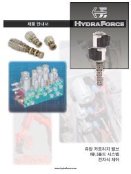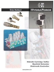
Series E Environmental Coils - HydraForce
Series E Environmental Coils - HydraForce
Series E Environmental Coils - HydraForce

Create successful ePaper yourself
Turn your PDF publications into a flip-book with our unique Google optimized e-Paper software.
COILS AND ELECTRONIC CONTROLS<br />
<strong>Series</strong> E <strong>Environmental</strong> <strong>Coils</strong><br />
NEW SERIES E WATER-PROOF / WEATHER-RESISTANT SOLENOID VALVE COILS<br />
New <strong>Series</strong> E coils are the latest innovation in coil technology<br />
from Hydraforce. They are designed to meet the demanding<br />
requirements of mobile and industrial applications where<br />
weather resistance is required. Models with Deutsch DT and<br />
Metri-Pack ® integral connectors and new dual leadwire models<br />
meet or exceed all IP69K standards for weather resistance,<br />
offering superior reliability under the most demanding conditions.<br />
<strong>Series</strong> E coils have passed what is known in the<br />
construction, agricultural and mobile equipment markets as<br />
the “Thermal Shock Dunk Test.”<br />
<strong>Series</strong> E coils feature a new, fully encapsulated coil winding<br />
technology. Deutsch and Metri-Pack ® connectors are molded<br />
into the coil encapsulation, assuring IP69K weather resistance.<br />
An external metal shell serves as the element to concentrate<br />
the magnetic flux for the coil winding and also functions as a<br />
rugged container for the coil. No O-rings or waterproofing kits<br />
are required.<br />
Models are available to fit most <strong>HydraForce</strong> valves. In most<br />
applications, these coils can be used to retrofit <strong>HydraForce</strong><br />
valves already in field operation and will offer superior<br />
weather resistance.<br />
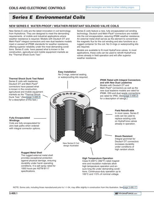
Thermal Shock Dunk Test Rated<br />
<strong>Series</strong> E coils with leadwires,<br />
Deutsch DT and Metri-Pack ®<br />
connectors have passed what<br />
is known in the construction,<br />
agricultural and mobile equipment<br />
markets as the “Thermal Shock<br />
Dunk Test.” (See page 3.400.2<br />
for a description of this test.)<br />
Easy Installation<br />
No O-rings, external sealing,<br />
or waterproofing kits required.<br />
IP69K Rated with Integral Connectors<br />
and with New Dual Leadwires<br />
Models with Deutsch DT and<br />
Metri-Pack ® connectors as well as the<br />
new dual leadwire models are rated for<br />
IP69K. DIN and dual spade connections<br />
are rated for IP65. (See page 3.400.2<br />
for a description of ratings.)<br />
Fully Encapsulated<br />
Windings<br />
<strong>Coils</strong> are fully encapsulated for<br />
zero leak paths when ordered<br />
with integral connector options.<br />
Field Retrofit-able<br />
In most cases, <strong>Series</strong> E<br />
coils can be used to<br />
replace existing coils<br />
on <strong>HydraForce</strong> valves<br />
already in operation.<br />
Rugged Metal Shell<br />
The rugged external metal shell<br />
provides exceptional protection<br />
against physical damage, ensuring<br />
durability under harsh operating<br />
conditions. It is salt spray rated for<br />
1000 hours per ASTM B117<br />
specifications.<br />
New <strong>Series</strong> E Coil<br />
design illustrated<br />
High Temperature Operation<br />
Class N 200°C (392°F) rated magnet<br />
wire and insulation materials allow<br />
high temperature operation and ensure<br />
long life under demanding conditions.<br />
Continuous-duty operation up to<br />
100°C and 115% of nominal voltage.<br />
Shock Resistant<br />
Integral grommet for<br />
Deutsch DT connectors<br />
increases durability<br />
under conditions of<br />
high random shock.<br />
NOTE: Some coils, including those manufactured prior to 1-1-04, may differ slightly in construction from this illustration. See page 3.400.17<br />
3.400.1<br />
®<br />
HYDRAFORCE.com
®<br />
HYDRAFORCE<br />
<strong>Series</strong> E <strong>Environmental</strong> <strong>Coils</strong><br />
IMPROVING DURABILITY TO ASSURE LONG LIFE IN THE HARSHEST ENVIRONMENTS<br />
<strong>HydraForce</strong> has made design changes to the industry-leading<br />
environmentally-hardened <strong>Series</strong> E coils. The new design<br />
provides longer life under high-temperature conditions, as well<br />
as easier and more convenient interchange with our <strong>Series</strong> D<br />
standard-duty coils.<br />
The Story Behind the Ratings<br />
To appreciate the performance of the new <strong>Series</strong> E coils, it is<br />
helpful to have a working knowledge of the testing conducted<br />
to assure coil life in the harshest environments. Many OEMs<br />
request a coil that is IP67 or IP69 rated. These ratings do not<br />
address the issue of the effect of high temperatures on coil life<br />
and operation. Therefore they are of limited value in evaluating<br />
the suitability of a coil for use in typical mobile equipment<br />
applications.<br />
Why temperature matters: When a coil is heated, the air<br />
inside the coil expands, creating internal pressure, causing the<br />
heated air to attempt to exit the coil. If the coil is then<br />
submerged in cold water, the air within the coil cools and<br />
contracts, drawing water into the coil through any seams or<br />
voids in the coil encapsulant. Eventually the water will fi nd its<br />
way into the winding area, causing the coil winding to corrode<br />
or short-circuit, resulting in coil failure.<br />
IP ratings are international specifi cations for electrical equipment<br />
which defi ne various levels of protection against failure<br />
resulting from contamination by water or other foreign substances.<br />
The IP67 rating is based on submerging the coil in<br />
one meter of water for 30 minutes. The coil is then inspected<br />
for evidence of water infi ltration. The IP67 specifi cation loosely<br />
states that “ingress of water in quantities causing harmful effect<br />
shall not occur.” The exact meaning of the phrase “harmful<br />
effect” is not precisely defi ned, and is therefore open to some<br />
interpretation. In this test, the coil is not subjected to high temperatures,<br />
so the effects of thermal stress are not<br />
considered.<br />
The IP69 rating, which is currently only part of the DIN version<br />
of this specifi cation, fi rst requires that the coil pass the test for<br />
IP67 as described above. Beyond that, the coil and its integral<br />
electrical connector are subjected to a rigorous high-pressure<br />
water spray. The water is mixed with detergent, is held at a<br />
temperature of 80°C., and is sprayed at the coil from a distance<br />
of 100 mm (4 inches) at a pressure of 100 bar (1450 psi).<br />
Again, the specifi cation does not precisely defi ne the amount<br />
of water ingress that would be considered unacceptable.<br />
<strong>HydraForce</strong> Ratings<br />
Working with major mobile equipment OEMs, <strong>HydraForce</strong><br />
has developed even more rigorous tests that are designed to<br />
assure that our coils will perform reliably under the harshest<br />
real-world application conditions. Both our original and our<br />
new <strong>Series</strong> E coils meet or exceed the requirements of what is<br />
known as the “Thermal Shock Dunk Test.” In this test the coil<br />
is thermally “soaked” for two hours in an ambient temperature<br />
of 100°C. The coil is then immersed immediately in a 0°C saltwater<br />
bath for two hours. This procedure is repeated ten times.<br />
The coil is then inspected for water ingress. By Hydraforce’s<br />
standards, the coil is considered to have passed this test if<br />
there is NO detectable water ingress, as determined by visual<br />
inspection and a “high pot” test. This standard requires a totally<br />
sealed coil that is impervious to moisture infi ltration, even<br />
under widely varying ambient thermal conditions.<br />
The new <strong>Series</strong> E coils can now withstand at least 10<br />
cycles of the “Thermal Shock Dunk Test.”<br />
In addition to the requirements of the industry-recognized,<br />
“Thermal Shock Dunk Test,” described above, <strong>HydraForce</strong><br />
further tests these coils for durability against failure due to<br />
vibration, as well as against failure due to the application of<br />
voltage above the coil’s standard duty rating while it is simultaneously<br />
subjected to continually varying ambient temperatures.<br />
Beyond enhancing the durability of the coils, we have<br />
decreased the wattage by approximately 10%. This reduces<br />
the power consumption and also allows the operating<br />
temperature range to be extended. The new design also<br />
improves the ease and convenience of interchanging these<br />
coils with <strong>HydraForce</strong>’s <strong>Series</strong> D (standard duty) coils, the<br />
original <strong>Series</strong> E coils, as well as the older “W-style” waterproof<br />
option. The new <strong>Series</strong> E coils use the same retaining nuts as<br />
the <strong>Series</strong> D coils, simplifying interchangeability, inventory and<br />
assembly requirements and procedures.<br />
See page 3.400.17 for detailed information describing the<br />
differences between the original <strong>Series</strong> E coils and the new<br />
<strong>Series</strong> E coils, including part number cross-references for the<br />
coils, the retaining nuts, and the spacers used on the dualsolenoid<br />
valves.<br />
®<br />
HYDRAFORCE.com<br />
3.400.2
COILS AND ELECTRONIC CONTROLS<br />
<strong>Series</strong> E <strong>Environmental</strong> <strong>Coils</strong><br />
OUR COIL TESTING PROGRAM IS THE MOST STRINGENT AND RIGOROUS IN THE INDUSTRY<br />
1.) Extended Thermal Shock Immersion Test – IP67<br />
Ref. Exceeds IP67 per standard EN60529<br />
4.) Vibration Test<br />
This accelerated test<br />
simulates random vibration<br />
that the coil will encounter<br />
when used on heavy-duty<br />
equipment.<br />
Functional performance is<br />
monitored under the following<br />
vibration levels shown in the<br />
table below for 72 hours in each<br />
of the three perpendicular axes.<br />
The coil is then checked for<br />
impaired function, loose parts<br />
and fatigue cracks induced by<br />
the test.<br />
The purpose of this test is to try to induce cracks in the<br />
encapsulation of the coil.<br />
The coil is heated for two hours at an ambient temperature<br />
of 105°C (±5°C), then immediately immersed in a solution<br />
of water, detergent and salt at a temperature of 0° to 5°C for<br />
two hours. The coils is then visually inspected for cracks and<br />
water penetration. This process is repeated ten times.<br />
2.) Salt Spray Test DIN 50 021 Level 1<br />
(Ref: Standard ASTM B117)<br />
This accelerated test is<br />
designed to simulate the<br />
corrosive environment that<br />
the coil will encounter during<br />
the life of the vehicle.<br />
The coil is subjected to a<br />
continuous salt spray as per<br />
ASTN B117 for a period of 20<br />
hours. The coil is then rinsed<br />
and dried.<br />
3.) Inorganic Dust Test<br />
ANSI/ASAE EP455 Section 5.3<br />
This tests for the effects of<br />
dust on the coil.<br />
The coil is placed in a dust<br />
chamber containing the equivalent<br />
of air cleaner fi ne dust.<br />
Suffi cient air movement is<br />
provided to maintain a minimum<br />
0.88g per cubic meter with the<br />
coil positioned in its normal<br />
mounting position. The test is<br />
run for a minimum of 24 hours.<br />
Vibration Test Profile:<br />
Measured<br />
Accelerated<br />
Frequenc y PSD Acceleration Test PSD<br />
(Hz) (G 2/Hz) Factor (G 2/Hz)<br />
20 0.422 x 2 0.844<br />
25 0.781 x 2 1.562<br />
76 0.174 x 2 0.348<br />
137 0.00283 x 7.2 0.020374<br />
216 0.00073 x 7.2 0.005256<br />
261 0.00119 x 7.2 0.008568<br />
320 0.00042 x 7.2 0.003024<br />
399 0.0000415 x 7.2 0.000298<br />
626 0.0000265 x 7.2 0.0001908<br />
712 0.000452 x 7.2 0.0032544<br />
799 0.0000491 x 7.2 0.00035352<br />
966 0.00117 x 7.2 0.008424<br />
1424 0.00000965 x 7.2 0.00006948<br />
1597 0.00012 x 7.2 0.000864<br />
1996 0.0000154 x 7.2 0.0001108<br />
3.400.3<br />
®<br />
HYDRAFORCE.com
®<br />
HYDRAFORCE<br />
<strong>Series</strong> E <strong>Environmental</strong> <strong>Coils</strong><br />
COIL TESTING PROGRAM (cont’d)<br />
5.) Operating Shock<br />
7.) Bench Handling Shock<br />
This test simulates sudden,<br />
severe shock induced when<br />
the vehicle is driven over<br />
rough terrain.<br />
The coil must withstand a 5<br />
ms pulse of 490 m/sec 2 (50 g).<br />
Impaired function, loose parts,<br />
and fatigue cracks caused by<br />
this test result in part rejection.<br />
The test is repeated a total of<br />
fi ve times in each of the three<br />
perpendicular axes.<br />
This test simulates the effects<br />
of dropping a coil while it is<br />
being handled.<br />
The coil is dropped from a<br />
distance of 450mm (±5mm) onto<br />
a solid oak bench top at least<br />
44mm thick. The test is repeated<br />
by dropping the coil once on all<br />
practical edges and faces.<br />
Impaired function as a result of<br />
this test is cause for rejection.<br />
6.) Chemical Resistance<br />
8.) Storage Temperature<br />
<strong>Coils</strong> may be subjected to<br />
various chemicals throughout<br />
their life. In this test a coil is<br />
completely immersed in only<br />
one each of the following fl uids<br />
for a period of 5 minutes. Twelve<br />
coils are used at a time. After<br />
immersion the coils are heated for four hours at 50°C and the<br />
cycle is repeated for a total of ten trials. Impaired function as a<br />
result of this test is cause for failure.<br />
• Gasoline<br />
• Diesel Fuel<br />
• Engine Oil<br />
• Phosphate Wash<br />
• Hydraulic Fluid • Degreaser<br />
• Bearing Grease • Windshield Washer Fluid<br />
• Antifreeze<br />
• Battery Acid<br />
• Fertilizer (28% Nitrogen<br />
with ammonium nitrate<br />
and urea at a pH of 5)<br />
This test simulates the effects of storage in extreme<br />
temperatures for some time.<br />
While not in operation, the coil is subjected to +105°C and<br />
then –55°C for 20 hours each. Impaired function as a result<br />
of this test is cause for rejection.<br />
9.) Humidity<br />
This test simulates the effects<br />
of relative humidity on the<br />
coil.<br />
The coil is soaked at 40°C<br />
and 95% relative humidity for<br />
168 hours each while the coil<br />
is not in operation. Impaired<br />
function as a result of this test<br />
is cause for rejection.<br />
®<br />
HYDRAFORCE.com<br />
3.400.4
COILS AND ELECTRONIC CONTROLS<br />
<strong>Series</strong> E <strong>Environmental</strong> <strong>Coils</strong><br />
COIL TESTING PROGRAM (cont’d)<br />
10.) Continuous Immersion – IP68<br />
Ref. Standard EN60529<br />
11.) Maximum Load Cycling<br />
ON<br />
ON – OFF<br />
In this test the coil is immersed while powered on.<br />
The coil is immersed in 1 meter of water at an ambient<br />
temperature of 25°C (±5°C) for 120 hours while powered<br />
according to the chart below. Impaired function as a result<br />
of this test is cause for rejection.<br />
% of NOMINAL VOLTAGE<br />
140<br />
130<br />
120<br />
110<br />
100<br />
90<br />
80<br />
70<br />
60<br />
50<br />
40<br />
30<br />
20<br />
10<br />
0<br />
0<br />
2<br />
TEST VOLTAGE<br />
Percent of Nominal for 24-Hour Period<br />
4 6<br />
133% 133%<br />
113% 113%<br />
8<br />
75%<br />
10 12 14<br />
TIME (Hours)<br />
16<br />
18<br />
20 22 24<br />
This accelerated test simulates temperature cycling<br />
to induce cracks or separation between components<br />
of the coil.<br />
<strong>Coils</strong> are installed in an environmental chamber set to 85°C<br />
and 133% of nominal voltage is applied for 1 hour. After<br />
1 hour, the power is immediately switched off and back on<br />
within 2 seconds. 133% of nominal voltage is then applied for<br />
a period of 5 minutes. After 5 minutes, power is immediately<br />
switched off and then back on within 2 seconds. This<br />
5-minute cycle is repeated for a total of 168 hours (power is<br />
turned off and on within 2 minutes every 5 minutes). Cracks<br />
in the encapsulation, separation in components, or impaired<br />
function are cause for rejection.<br />
12.) Jump Start<br />
220% of<br />
Nominal<br />
Voltage<br />
This test simulates the voltage required to jump start<br />
heavy equipment.<br />
The coil is thermally soaked in an environmental chamber<br />
at 70°C for 2 hours. It is then subjected to 220% of nominal<br />
voltage for 5 minutes.<br />
3.400.5<br />
®<br />
HYDRAFORCE.com
®<br />
HYDRAFORCE<br />
<strong>Series</strong> E <strong>Environmental</strong> <strong>Coils</strong><br />
COIL TESTING PROGRAM (cont’d)<br />
13.) High Pressure Cleaning – IP69K<br />
Ref. Standard DIN 40 050, part 9<br />
14.) Combined Operating Voltage, Humidity<br />
and Temperature (continued)<br />
This test simulates highpressure<br />
steam-jet cleaning<br />
of a component.<br />
14.) Combined Operating Voltage, Humidity<br />
and Temperature<br />
% of NOMINAL VOLTAGE<br />
140<br />
130<br />
120<br />
110<br />
100<br />
90<br />
80<br />
70<br />
60<br />
50<br />
40<br />
30<br />
20<br />
10<br />
0<br />
0<br />
OPERATING VOLTAGE<br />
Percent of Nominal for 6-Hour Period<br />
133%<br />
1 2<br />
3<br />
TIME (Hours)<br />
4<br />
5 6<br />
ON – OFF<br />
This test simulates the combined effects of some of the<br />
previous tests.<br />
The coil is simultaneously subjected to the voltage, temperature<br />
and humidity profi les shown in the graphs below. The<br />
cycle is repeated for a total of 600 hours (25 days). The coils<br />
are inspected every 20 cycles for cracks in the encapsulation,<br />
separation of components, or impaired function as a result of<br />
this test. Any induced fl aws will result in rejection.<br />
TEMPERATURE (°C)<br />
% RELATIVE HUMIDITY<br />
90<br />
80<br />
70<br />
60<br />
50<br />
40<br />
30<br />
20<br />
10<br />
0<br />
-10<br />
-20<br />
-30<br />
-40<br />
-50<br />
80<br />
70<br />
60<br />
50<br />
40<br />
30<br />
20<br />
10<br />
0<br />
OPERATING TEMPERATURE<br />
70°C Max.<br />
-40°C Min.<br />
1 2 3 4 5 6<br />
TIME (Hours)<br />
OPERATING HUMIDITY<br />
70%<br />
25%<br />
0<br />
0<br />
1 2<br />
3<br />
TIME (Hours)<br />
4<br />
5 6<br />
®<br />
HYDRAFORCE.com<br />
3.400.6
COILS AND ELECTRONIC CONTROLS<br />
<strong>Series</strong> E <strong>Environmental</strong> <strong>Coils</strong><br />
08-SIZE SERIES E COILS (also for use on 98-size screw-in spool-type valves)<br />
1.40<br />
35.6<br />
Dual Coil for SP08-47, SP08-57,<br />
SP08-58, SV08-47, SV08-58 valves<br />
1.43<br />
36.3<br />
Dual Coil for SP08-47, SP08-57,<br />
SP08-58, SV08-47, SP08-58 valves<br />
1.41<br />
35.8<br />
DIA.<br />
1.41<br />
35.8<br />
DIA.<br />
1.43<br />
36.3<br />
2.92<br />
74.2<br />
1.43<br />
36.3<br />
2.92<br />
74.2<br />
INCH<br />
MILLIMETRE<br />
INCH<br />
MILLIMETRE<br />
EY<br />
IP69K Rated 08-Size Coil<br />
Thermal Shock Dunk Test Rated Coil<br />
Metri-Pack ® 150 Connector<br />
Mating Connector: Delphi Packard No. 12052641; HF Part No. 6110119<br />
ER<br />
IP69K Rated 08-Size Coil<br />
Thermal Shock Dunk Test Rated Coil<br />
Deutsch DT04-2P Connector<br />
Mating Connector: Deutsch No. DT06-2S — HF Part No. 4001417<br />
EY<br />
Coil<br />
Part No.<br />
4303410<br />
4303412<br />
4303420<br />
4303424<br />
EY/Z*<br />
Coil<br />
Part No.<br />
4303810<br />
4303812<br />
—<br />
4303824<br />
* Models with Zener Diode<br />
ER<br />
Coil<br />
Part No.<br />
4303610<br />
4303612<br />
4303620<br />
4303624<br />
ER/Z*<br />
Coil<br />
Part No.<br />
4304010<br />
4304012<br />
4304020<br />
4304024<br />
Operating<br />
Voltage<br />
10 VDC<br />
12 VDC<br />
20 VDC<br />
24 VDC<br />
Resistance<br />
at 20°C<br />
6.2 ohms<br />
8.8 ohms<br />
23.9 ohms<br />
33.8 ohms<br />
Initial<br />
Current<br />
Draw<br />
1.6 amps<br />
1.4 amps<br />
0.8 amps<br />
0.7 amps<br />
Power<br />
15.9 watts<br />
17.2 watts<br />
15.3 watts<br />
16.6 watts<br />
Coil<br />
Weight<br />
136 g. (4.8 oz.)<br />
136 g. (4.8 oz.)<br />
136 g. (4.8 oz.)<br />
136 g. (4.8 oz.)<br />
Note: Electrical specifications for <strong>Series</strong> E coils differ from those for standard<br />
<strong>HydraForce</strong> coils. (Refer to page 3.200.1 for standard coil specifi cations.)<br />
% OF RATED VOLTAGE<br />
120<br />
110<br />
100<br />
90<br />
80<br />
70<br />
60<br />
50<br />
CONTINUOUS DUTY OPERATING RANGE<br />
Minimum Voltage Required for Pull-In; 32 cSt/150 sus oil at 40°C<br />
-40<br />
-30<br />
Operating Range<br />
-20 -10<br />
0 10 20 30 40 50 60 70 80 90 100<br />
AMBIENT TEMPERATURE (C)<br />
3.400.7<br />
®<br />
HYDRAFORCE.com
®<br />
HYDRAFORCE<br />
<strong>Series</strong> E <strong>Environmental</strong> <strong>Coils</strong><br />
08-SIZE SERIES E COILS (also for use on 98-size screw-in spool-type valves)<br />
1.50<br />
38.1<br />
Dual Coil for SP08-47, SP08-57,<br />
SP08-58, SV08-47, SP08-58 valves<br />
1.41<br />
35.8<br />
DIA.<br />
1.43<br />
36.3<br />
2.92<br />
74.2<br />
INCH<br />
MILLIMETRE<br />
EL<br />
IP69K Rated 08-Size Coil<br />
Thermal Shock Dunk Test Rated Coil<br />
EL Coil<br />
36" Wire<br />
Part No.<br />
4308710<br />
4308712<br />
—<br />
4308724<br />
EL Coil<br />
18" Wire<br />
Part No.<br />
4305110<br />
4305112<br />
4305120<br />
4305124<br />
* Models with Zener Diode<br />
EL/Z* Coil<br />
18" Wire<br />
Part No.<br />
—<br />
4306812<br />
—<br />
4306824<br />
Operating<br />
Voltage<br />
10 VDC<br />
12 VDC<br />
20 VDC<br />
24 VDC<br />
Resistance<br />
at 20°C<br />
6.2 ohms<br />
8.8 ohms<br />
23.9 ohms<br />
33.8 ohms<br />
Initial<br />
Current<br />
Draw<br />
1.6 amps<br />
1.4 amps<br />
0.8 amps<br />
0.7 amps<br />
Power<br />
15.9 watts<br />
17.2 watts<br />
15.3 watts<br />
16.6 watts<br />
Coil<br />
Weight<br />
136 g. (4.8 oz.)<br />
136 g. (4.8 oz.)<br />
136 g. (4.8 oz.)<br />
136 g. (4.8 oz.)<br />
Note: Electrical specifications for <strong>Series</strong> E coils differ from those for standard<br />
<strong>HydraForce</strong> coils. (Refer to page 3.200.1 for standard coil specifi cations.)<br />
% OF RATED VOLTAGE<br />
120<br />
110<br />
100<br />
90<br />
80<br />
70<br />
60<br />
50<br />
CONTINUOUS DUTY OPERATING RANGE<br />
Minimum Voltage Required for Pull-In; 32 cSt/150 sus oil at 40°C<br />
-40<br />
-30<br />
Operating Range<br />
-20 -10<br />
0 10 20 30 40 50 60 70 80 90 100<br />
AMBIENT TEMPERATURE (C)<br />
®<br />
HYDRAFORCE.com<br />
3.400.8
COILS AND ELECTRONIC CONTROLS<br />
<strong>Series</strong> E <strong>Environmental</strong> <strong>Coils</strong><br />
08-SIZE SERIES E COILS (also for use on 98-size screw-in spool-type valves)<br />
1.40<br />
35.6<br />
Dual Coil for SP08-47, SP08-57,<br />
SP08-58, SV08-47, SV08-58 valves<br />
1.04<br />
26.4<br />
Dual Coil for SP08-47, SP08-57,<br />
SP08-58, SV08-47, SV08-58 valves<br />
1.14<br />
29.0<br />
1.41<br />
35.8<br />
DIA.<br />
1.41<br />
35.8<br />
DIA.<br />
0.21<br />
5.31<br />
INCH<br />
MILLIMETRE<br />
1.44<br />
36.6<br />
2.92<br />
74.2<br />
INCH<br />
MILLIMETRE<br />
1.11<br />
28.1<br />
1.43<br />
36.3<br />
2.92<br />
74.2<br />
EJ<br />
IP67 Rated 08-Size Coil<br />
Amp Jr. Timer Connector<br />
EG<br />
IP65 Rated 08-Size Coil; DIN 43650 Connector<br />
IP67 rated if used with sealed mating connector and gasket<br />
EJ<br />
Coil<br />
Part No.<br />
4306112<br />
4306124<br />
EJ/Z*<br />
Coil<br />
Part No.<br />
4305912<br />
4305924<br />
* Models with Zener Diode<br />
EG<br />
Coil<br />
Part No.<br />
4305862<br />
4305864<br />
EG/Z*<br />
Coil<br />
Part No.<br />
4305872<br />
4305874<br />
Operating<br />
Voltage<br />
12 VDC<br />
24 VDC<br />
Resistance<br />
at 20°C<br />
8.8 ohms<br />
33.8 ohms<br />
Initial<br />
Current<br />
Draw<br />
1.4 amps<br />
0.7 amps<br />
Power<br />
17.2 watts<br />
16.6 watts<br />
Coil<br />
Weight<br />
136 g. (4.8 oz.)<br />
136 g. (4.8 oz.)<br />
Note: Electrical specifications for <strong>Series</strong> E coils differ from those for standard<br />
<strong>HydraForce</strong> coils. (Refer to page 3.200.1 for standard coil specifi cations.)<br />
% OF RATED VOLTAGE<br />
120<br />
110<br />
100<br />
90<br />
80<br />
70<br />
60<br />
50<br />
CONTINUOUS DUTY OPERATING RANGE<br />
Minimum Voltage Required for Pull-In; 32 cSt/150 sus oil at 40°C<br />
-40<br />
-30<br />
Operating Range<br />
-20 -10<br />
0 10 20 30 40 50 60 70 80 90 100<br />
AMBIENT TEMPERATURE (C)<br />
3.400.9<br />
®<br />
HYDRAFORCE.com
®<br />
HYDRAFORCE<br />
<strong>Series</strong> E <strong>Environmental</strong> <strong>Coils</strong><br />
10-SIZE SERIES E COILS (Also for use on 12, 16, 20, 38 and 58 size poppet valves and 90-size spool valves)<br />
1.62<br />
41.1<br />
Dual Coil for SP10-47, SP10-57,<br />
SP10-58, SV10-47, SV10-57, SV10-58<br />
1.65<br />
41.9<br />
Dual Coil for SP10-47, SP10-57,<br />
SP10-58, SV10-47, SV10-57, SV10-58<br />
1.84<br />
46.7<br />
DIA.<br />
1.84<br />
46.7<br />
DIA.<br />
1.96<br />
49.9<br />
1.96<br />
49.9<br />
3.98<br />
101.1<br />
3.98<br />
101.1<br />
INCH<br />
MILLIMETRE<br />
INCH<br />
MILLIMETRE<br />
EY<br />
IP69K Rated 10-Size Coil<br />
Thermal Shock Dunk Test Rated Coil<br />
Metri-Pack ® 150 Connector<br />
Mating Connector: Delphi Packard No. 12052641; HF Part No. 6110119<br />
ER<br />
IP69K Rated 10-Size Coil<br />
Thermal Shock Dunk Test Rated Coil<br />
Deutsch DT04-2P Connector<br />
Mating Connector: Deutsch No. DT06-2S; HF Part No. 4001417<br />
EY<br />
Coil<br />
Part No.<br />
4303510<br />
4303512<br />
4303520<br />
4303524<br />
EY/Z*<br />
Coil<br />
Part No.<br />
4303910<br />
4303912<br />
—<br />
4303924<br />
* Models with Zener Diode<br />
ER<br />
Coil<br />
Part No.<br />
4303710<br />
4303712<br />
4303720<br />
4303724<br />
ER/Z*<br />
Coil<br />
Part No.<br />
4304110<br />
4304112<br />
4304120<br />
4304124<br />
Operating<br />
Voltage<br />
10 VDC<br />
12 VDC<br />
20 VDC<br />
24 VDC<br />
Resistance<br />
at 20°C<br />
5.0 ohms<br />
7.1 ohms<br />
19.1 ohms<br />
28.5 ohms<br />
Initial<br />
Current<br />
Draw<br />
2.0 amps<br />
1.7 amps<br />
1.0 amps<br />
0.8 amps<br />
Power<br />
20.0 watts<br />
20.5 watts<br />
19.1 watts<br />
18.2 watts<br />
Coil<br />
Weight<br />
408 g. (14.4 oz.)<br />
408 g. (14.4 oz.)<br />
408 g. (14.4 oz.)<br />
408 g. (14.4 oz.)<br />
Please note: Electrical specifications for <strong>Series</strong> E coils differ from those for standard<br />
<strong>HydraForce</strong> coils. (Refer to page 3.200.1 for standard coil specifi cations.)<br />
% OF RATED VOLTAGE<br />
120<br />
110<br />
100<br />
90<br />
80<br />
70<br />
60<br />
50<br />
-40<br />
CONTINUOUS DUTY OPERATING RANGE<br />
Minimum Voltage Required for Pull-In; 32 cSt/150 sus oil at 40°C<br />
-30<br />
Operating Range<br />
-20 -10<br />
0 10 20 30 40 50 60 70 80 90 100<br />
AMBIENT TEMPERATURE (C)<br />
®<br />
HYDRAFORCE.com<br />
3.400.10
COILS AND ELECTRONIC CONTROLS<br />
<strong>Series</strong> E <strong>Environmental</strong> <strong>Coils</strong><br />
10-SIZE SERIES E COILS (Also for use on 12-size poppet valves and 16-size poppet valves)<br />
1.72<br />
43.7<br />
Dual Coil for SP10-47, SP10-57,<br />
SP10-58, SV10-47, SV10-57, SV10-58<br />
1.84<br />
46.7<br />
DIA.<br />
1.96<br />
49.9<br />
3.98<br />
101.1<br />
INCH<br />
MILLIMETRE<br />
EL<br />
IP69K Rated 10-Size Coil — Thermal Shock Dunk Test Rated Coil<br />
EL Coil<br />
36" Wire<br />
Part No.<br />
EL Coil<br />
18" Wire<br />
Part No.<br />
EL/Z* Coil<br />
18" Wire<br />
Part No.<br />
4317210<br />
4317212<br />
—<br />
4317224<br />
4305710<br />
4305712<br />
4305720<br />
4305724<br />
—<br />
4307112<br />
—<br />
4307124<br />
* Models with Zener Diode<br />
Operating<br />
Voltage<br />
10 VDC<br />
12 VDC<br />
20 VDC<br />
24 VDC<br />
Resistance<br />
at 20°C<br />
5.0 ohms<br />
7.1 ohms<br />
19.1 ohms<br />
28.5 ohms<br />
Initial<br />
Current<br />
Draw<br />
2.0 amps<br />
1.7 amps<br />
1.0 amps<br />
0.8 amps<br />
Power<br />
20.0 watts<br />
20.5 watts<br />
19.1 watts<br />
18.2 watts<br />
Coil<br />
Weight<br />
408 g. (14.4 oz.)<br />
408 g. (14.4 oz.)<br />
408 g. (14.4 oz.)<br />
408 g. (14.4 oz.)<br />
Note: Electrical specifications for <strong>Series</strong> E coils differ from those for standard<br />
<strong>HydraForce</strong> coils. (Refer to page 3.200.1 for standard coil specifi cations.)<br />
% OF RATED VOLTAGE<br />
120<br />
110<br />
100<br />
90<br />
80<br />
70<br />
60<br />
50<br />
-40<br />
CONTINUOUS DUTY OPERATING RANGE<br />
Minimum Voltage Required for Pull-In; 32 cSt/150 sus oil at 40°C<br />
-30<br />
Operating Range<br />
-20 -10<br />
0 10 20 30 40 50 60 70 80 90 100<br />
AMBIENT TEMPERATURE (C)<br />
3.400.11<br />
®<br />
HYDRAFORCE.com
®<br />
HYDRAFORCE<br />
<strong>Series</strong> E <strong>Environmental</strong> <strong>Coils</strong><br />
10-SIZE SERIES E COILS (Also for use on 12-size poppet valves and 16-size poppet valves)<br />
1.62<br />
41.1<br />
Dual Coil for SP10-47, SP10-57,<br />
SP10-58, SV10-47, SV10-57, SV10-58<br />
1.25<br />
31.8<br />
Dual Coil for SP10-47, SP10-57,<br />
SP10-58, SV10-47, SV10-57, SV10-58<br />
1.14<br />
29.0<br />
1.84<br />
46.7<br />
DIA.<br />
1.84<br />
46.7<br />
DIA.<br />
0.75<br />
19.1<br />
1.96<br />
49.9<br />
INCH<br />
MILLIMETRE<br />
3.98<br />
101.1<br />
INCH<br />
MILLIMETRE<br />
1.10<br />
27.9<br />
1.96<br />
49.9<br />
3.98<br />
101.1<br />
EJ<br />
IP67 Rated 10-Size Coil<br />
Amp Jr. Timer Connector<br />
EG<br />
IP65 Rated 10-Size Coil; DIN 43650 Connector<br />
IP67 rated if used with sealed mating connector and gasket<br />
EJ<br />
Coil<br />
Part No.<br />
—<br />
4305612<br />
—<br />
4305624<br />
EJ/Z*<br />
Coil<br />
Part No.<br />
—<br />
4305412<br />
—<br />
4305424<br />
* Models with Zener Diode<br />
EG<br />
Coil<br />
Part No.<br />
4305881<br />
4305882<br />
4305883<br />
4305884<br />
EG/Z*<br />
Coil<br />
Part No.<br />
4305891<br />
4305892<br />
4305893<br />
4305894<br />
Operating<br />
Voltage<br />
10 VDC<br />
12 VDC<br />
20 VDC<br />
24 VDC<br />
Resistance<br />
at 20°C<br />
5.0 ohms<br />
7.1 ohms<br />
19.1 ohms<br />
28.5 ohms<br />
Initial<br />
Current<br />
Draw<br />
2.0 amps<br />
1.7 amps<br />
1.0 amps<br />
0.8 amps<br />
Power<br />
20.0 watts<br />
20.5 watts<br />
19.1 watts<br />
18.2 watts<br />
Coil<br />
Weight<br />
408 g. (14.4 oz.)<br />
408 g. (14.4 oz.)<br />
408 g. (14.4 oz.)<br />
408 g. (14.4 oz.)<br />
Note: Electrical specifications for <strong>Series</strong> E coils differ from those for standard<br />
<strong>HydraForce</strong> coils. (Refer to page 3.200.1 for standard coil specifi cations.)<br />
% OF RATED VOLTAGE<br />
120<br />
110<br />
100<br />
90<br />
80<br />
70<br />
60<br />
50<br />
-40<br />
CONTINUOUS DUTY OPERATING RANGE<br />
Minimum Voltage Required for Pull-In; 32 cSt/150 sus oil at 40°C<br />
-30<br />
Operating Range<br />
-20 -10<br />
0 10 20 30 40 50 60 70 80 90 100<br />
AMBIENT TEMPERATURE (C)<br />
®<br />
HYDRAFORCE.com<br />
3.400.12
COILS AND ELECTRONIC CONTROLS<br />
<strong>Series</strong> E <strong>Environmental</strong> <strong>Coils</strong><br />
70-SIZE SERIES E COILS (For use on PFR and PV valves and on 10-, 12- and 16-size valves. )<br />
1.62<br />
41.1<br />
1.65<br />
41.9<br />
1.84<br />
46.7<br />
DIA.<br />
1.84<br />
46.7<br />
DIA.<br />
2.45<br />
62.3<br />
2.45<br />
62.3<br />
INCH<br />
MILLIMETRE<br />
INCH<br />
MILLIMETRE<br />
EY<br />
IP69K Rated 70-Size Coil<br />
Thermal Shock Dunk Test Rated Coil<br />
Metri-Pack ® 150 Connector<br />
Mating Connector: Delphi Packard No. 12052641<br />
HF Part No. 6110119<br />
ER<br />
IP69K Rated 70-Size Coil<br />
Thermal Shock Dunk Test Rated Coil<br />
Deutsch DT04-2P Connector<br />
Mating Connector: Deutsch No. DT06-2S<br />
HF Part No. 4001417<br />
EY Coil<br />
Part No.<br />
ER Coil<br />
Part No.<br />
Operating<br />
Voltage<br />
Resistance<br />
at 20°C<br />
Initial<br />
Current Draw<br />
Power<br />
Coil<br />
Weight<br />
4303112<br />
4303124<br />
4303212<br />
4303224<br />
12 VDC<br />
24 VDC<br />
4.5 ohms<br />
17.9 ohms<br />
2.7 amps<br />
1.3 amps<br />
32.8 watts<br />
30.3 watts<br />
408 g. (14.4 oz.)<br />
408 g. (14.4 oz.)<br />
Note: Electrical specifications for <strong>Series</strong> E coils differ from those for standard <strong>HydraForce</strong> coils.<br />
(Refer to page 3.200.1 for standard coil specifi cations.)<br />
% OF RATED VOLTAGE<br />
120<br />
110<br />
100<br />
90<br />
80<br />
70<br />
60<br />
50<br />
-40<br />
CONTINUOUS DUTY OPERATING RANGE<br />
Minimum Voltage Required for Pull-In; 32 cSt/150 sus oil at 40°C<br />
-30<br />
Operating Range<br />
-20 -10<br />
0 10 20 30 40 50 60 70 80 90 100<br />
AMBIENT TEMPERATURE (C)<br />
3.400.13<br />
®<br />
HYDRAFORCE.com
®<br />
HYDRAFORCE<br />
<strong>Series</strong> E <strong>Environmental</strong> <strong>Coils</strong><br />
EHPR-SIZE SERIES E COILS (Also for use on TS08-27, PV08 and 42-size valves.)<br />
1.40<br />
35.6<br />
1.46<br />
37.1<br />
1.34<br />
34.0<br />
DIA.<br />
1.34<br />
34.0<br />
DIA.<br />
1.53<br />
38.9<br />
1.53<br />
38.9<br />
INCH<br />
MILLIMETRE<br />
INCH<br />
MILLIMETRE<br />
EY<br />
IP69K Rated 08-Size Coil<br />
Thermal Shock Dunk Test Rated Coil<br />
Metri-Pack ® 150 Connector<br />
Mating Connector: Delphi Packard No. 12052641<br />
HF Part No. 6110119<br />
ER<br />
IP69K Rated 08-Size Coil<br />
Thermal Shock Dunk Test Rated Coil<br />
Deutsch DT04-2P Connector<br />
Mating Connector: Deutsch No. DT06-2S<br />
HF Part No. 4001417<br />
EY Coil<br />
Part No.<br />
4304812<br />
4304824<br />
ER Coil<br />
Part No.<br />
4304712<br />
4304724<br />
* Models with Zener Diode<br />
ER/Z* Coil<br />
Part No.<br />
4320712<br />
4320724<br />
Operating<br />
Voltage<br />
12 VDC<br />
24 VDC<br />
Resistance<br />
at 20°C<br />
5.4 ohms<br />
21.7 ohms<br />
Initial<br />
Current Draw<br />
2.2 amps<br />
1.1 amps<br />
Power<br />
26.1 watts<br />
26.3 watts<br />
Coil<br />
Weight<br />
136 g. (4.8 oz.)<br />
136 g. (4.8 oz.)<br />
Note: Electrical specifications for <strong>Series</strong> E coils differ from those for standard<br />
<strong>HydraForce</strong> coils. (Refer to page 3.200.1 for standard coil specifi cations.)<br />
% OF RATED VOLTAGE<br />
120<br />
110<br />
100<br />
90<br />
80<br />
70<br />
60<br />
50<br />
CONTINUOUS DUTY OPERATING RANGE<br />
Minimum Voltage Required for Pull-In; 32 cSt/150 sus oil at 40°C<br />
-40<br />
-30<br />
Operating Range<br />
-20 -10<br />
0 10 20 30 40 50 60 70 80 90 100<br />
AMBIENT TEMPERATURE (C)<br />
®<br />
HYDRAFORCE.com<br />
3.400.14
COILS AND ELECTRONIC CONTROLS<br />
<strong>Series</strong> E <strong>Environmental</strong> <strong>Coils</strong><br />
12-SIZE SERIES E COILS (For 12 Size Spool Valves Only)<br />
1.77<br />
44.9<br />
1.80<br />
45.7<br />
1.81<br />
46.0<br />
2.19<br />
55.6<br />
INCH<br />
MILLIMETRE<br />
2.19<br />
55.6<br />
2.19<br />
55.6<br />
3.03<br />
76.8<br />
3.03<br />
76.8<br />
3.03<br />
76.8<br />
EY<br />
IP69K Rated 12-Size Coil<br />
Thermal Shock Dunk Test Rated<br />
Metri-Pack ® 150 Connector<br />
Mating Connector:<br />
Delphi Packard No. 12052641<br />
HF Part No. 6110119<br />
ER<br />
IP69K Rated 12-Size Coil<br />
Thermal Shock Dunk Test Rated<br />
Deutsch DT04-2P Connector<br />
Mating Connector:<br />
Deutsch No. DT06-2S — HF Part No. 4001417<br />
EG<br />
IP65 Rated 12-Size Coil<br />
DIN 43650 Connector<br />
Can be IP67 rated if used with<br />
sealed mating connector<br />
and gasket<br />
EY<br />
Coil<br />
Part No.<br />
EY/Z*<br />
Coil<br />
Part No.<br />
ER<br />
Coil<br />
Part No.<br />
ER/Z*<br />
Coil<br />
Part No.<br />
EG<br />
Coil<br />
Part No.<br />
Operating<br />
Voltage<br />
Resistance<br />
at 20°C<br />
Initial<br />
Current<br />
Draw<br />
Power<br />
Coil<br />
Weight<br />
6964012<br />
6964024<br />
4302206<br />
4302207<br />
4301212<br />
4301224<br />
4305512<br />
4305524<br />
6956012<br />
6956024<br />
12 VDC<br />
24 VDC<br />
4.6 ohms<br />
18.3 ohms<br />
2.6 amps<br />
1.3 amps<br />
31.1 watts<br />
31.0 watts<br />
1 kg. (2.2 lbs.)<br />
1 kg. (2.2 lbs.)<br />
* Models with Zener Diode<br />
% OF RATED VOLTAGE<br />
120<br />
110<br />
100<br />
90<br />
80<br />
70<br />
60<br />
50<br />
CONTINUOUS DUTY OPERATING RANGE<br />
Minimum Voltage at the Coil Required for Pull-In<br />
32 cSt/150 ssu oil at 40°C<br />
Operating Range<br />
-40 -30 -20 -10 0 10 20 30 40 50<br />
AMBIENT TEMPERATURE (°C)<br />
60 70<br />
3.400.15<br />
®<br />
HYDRAFORCE.com
12-SIZE SERIES E COILS (For 12 Size Spool Valves Only)<br />
®<br />
HYDRAFORCE<br />
<strong>Series</strong> E <strong>Environmental</strong> <strong>Coils</strong><br />
1.79<br />
45.6<br />
1.66<br />
42.2<br />
7.84<br />
199.1<br />
1.66<br />
42.2<br />
2.19<br />
55.6<br />
2.19<br />
55.6<br />
INCH<br />
MILLIMETRE<br />
2.19<br />
55.6<br />
Approx.<br />
Lead Length:<br />
16.34<br />
415<br />
3.03<br />
76.8<br />
3.03<br />
76.8<br />
3.03<br />
76.8<br />
ES<br />
IP65 Rated 12-Size Coil<br />
Dual Spades SAE J858a<br />
EW<br />
IP65 Rated 12-Size Coil<br />
Dual 18 Gauge Leads<br />
with Weather-Pack ® Connector<br />
Mating Connector: Delphi Packard No. 12015792<br />
EL<br />
IP65 Rated 12-Size Coil<br />
Dual Leads – 18 Gauge<br />
ES Coil<br />
Part No.<br />
EW Coil<br />
Part No.<br />
EL Coil<br />
Part No.<br />
Operating<br />
Voltage<br />
Resistance<br />
at 20°C<br />
Initial<br />
Current Draw<br />
Power<br />
Coil<br />
Weight<br />
—<br />
—<br />
6852010<br />
10 VDC<br />
3.2 ohms<br />
3.1 amps<br />
31.2 watts<br />
1 kg. (2.2 lbs.)<br />
6851012<br />
6853012<br />
6852012<br />
12 VDC<br />
4.6 ohms<br />
2.6 amps<br />
31.1 watts<br />
1 kg. (2.2 lbs.)<br />
6851024<br />
6853024<br />
6852024<br />
24 VDC<br />
18.3 ohms<br />
1.3 amps<br />
31.0 watts<br />
1 kg. (2.2 lbs.)<br />
% OF RATED VOLTAGE<br />
120<br />
110<br />
100<br />
90<br />
80<br />
70<br />
60<br />
50<br />
CONTINUOUS DUTY OPERATING RANGE<br />
Minimum Voltage at the Coil Required for Pull-In<br />
32 cSt/150 ssu oil at 40°C<br />
Operating Range<br />
-40 -30 -20 -10 0 10 20 30 40 50<br />
AMBIENT TEMPERATURE (°C)<br />
60 70<br />
®<br />
HYDRAFORCE.com<br />
3.400.16
COILS AND ELECTRONIC CONTROLS<br />
<strong>Series</strong> E <strong>Environmental</strong> <strong>Coils</strong><br />
SERIES E COILS PART NUMBER CROSS REFERENCE<br />
08-Size<br />
E-<strong>Coils</strong><br />
Original Design<br />
Manuf. before 1-1-04<br />
New Design<br />
Manuf. after 1-1-04<br />
10-Size<br />
E-<strong>Coils</strong><br />
Original Design<br />
Manuf. before 1-1-04<br />
New Design<br />
Manuf. after 1-1-04<br />
Code EY<br />
Metri-Pack ® 150<br />
Connector<br />
Top view shown<br />
w/o retaining nut<br />
10 VDC<br />
12 VDC<br />
20 VDC<br />
24 VDC<br />
Code ER<br />
Deutsch DT04-2P<br />
Connector<br />
Top view shown<br />
w/o retaining nut<br />
10 VDC<br />
12 VDC<br />
20 VDC<br />
24 VDC<br />
4300110<br />
4300112<br />
—<br />
4300124<br />
4300310<br />
4300312<br />
—<br />
4300324<br />
1.41<br />
1.41<br />
35.8 DIA. 35.8 DIA.<br />
4303410<br />
4303412<br />
4303420<br />
4303424<br />
1.41<br />
35.8 DIA. 1.41<br />
4303610<br />
4303612<br />
4303620<br />
4303624<br />
Code EY<br />
Metri-Pack ® 150<br />
Connector<br />
Top view shown<br />
w/o retaining nut<br />
1.84<br />
10 VDC<br />
4300210<br />
12 VDC<br />
4300212<br />
20 VDC<br />
—<br />
24 VDC<br />
4300224<br />
Code ER<br />
Deutsch DT04-2P<br />
Connector<br />
Top view shown<br />
w/o retaining nut<br />
35.8 DIA.<br />
10 VDC<br />
12 VDC<br />
20 VDC<br />
24 VDC<br />
4300410<br />
4300412<br />
—<br />
4300424<br />
46.7 DIA. 1.84<br />
46.7 DIA.<br />
4303510<br />
4303512<br />
4303520<br />
4303524<br />
1.84<br />
46.7 DIA. 1.84<br />
46.7 DIA.<br />
4303710<br />
4303712<br />
4303720<br />
4303724<br />
SERIES E COIL NUT & SPACER CROSS REF. FOR SPxx-47 & SVxx-47 DUAL SOLENOID VALVES<br />
For SP08-47<br />
& SV08-47<br />
<strong>Series</strong> Valves<br />
Retaining Nut<br />
for SP08-47’s<br />
& SV08-47’s<br />
without Manual<br />
Override<br />
Part Number:<br />
Retaining Nut<br />
for SP08-47M’s<br />
& SV08-47M’s<br />
with Manual<br />
Override<br />
Retaining Nut and<br />
Spacer for Original<br />
E-Coil Design<br />
Manuf. before 1-1-04<br />
Retaining Nut and<br />
Spacer for New<br />
E-Coil Design<br />
Manuf. after 1-1-04<br />
Nut: 4502960 Nut: 7004400<br />
For SP10-47<br />
& SV10-47<br />
<strong>Series</strong> Valve<br />
Retaining Nut and<br />
Spacer for Original<br />
E-Coil Design<br />
Manuf. before 1-1-04<br />
Retaining Nut and<br />
Spacer for New<br />
E-Coil Design<br />
Manuf. after 1-1-04<br />
Retaining Nut<br />
for SP10-47’s<br />
& SV10-47’s<br />
without Manual<br />
Override<br />
Part Number: Nut: 4502960 Nut: 7004400<br />
Retaining Nut<br />
for SP10-47M’s<br />
& SV10-47M’s<br />
with Manual<br />
Override<br />
Part Number:<br />
Nut: 4528150 Nut: 4528180<br />
Part Number:<br />
Nut: 4527160 Nut: 4527540<br />
Coil Spacer<br />
for all SP08-47<br />
& SV08-47 <strong>Series</strong><br />
Valves<br />
(installs between<br />
the two coils)<br />
1.41<br />
35.8<br />
O.D.<br />
1.41<br />
35.8<br />
O.D.<br />
Coil Spacer<br />
for all SP10-47<br />
& SV10-47 <strong>Series</strong><br />
Valves<br />
(installs between<br />
the two coils)<br />
1.84<br />
46.6<br />
O.D.<br />
1.84<br />
46.6<br />
O.D.<br />
Part Number:<br />
Spacer: 4514810 Spacer: 4534720<br />
Part Number:<br />
Spacer: 4514130 Spacer: 4539700<br />
3.400.17<br />
®<br />
HYDRAFORCE.com
®<br />
HYDRAFORCE<br />
<strong>Series</strong> E <strong>Environmental</strong> <strong>Coils</strong><br />
SERIES E COIL NUT CROSS REFERENCE<br />
Valve Models<br />
Retaining Nuts<br />
for Original<br />
E-Coil Design<br />
Manufactured<br />
before 1-1-04<br />
Retaining Nuts<br />
for New E-Coil<br />
Design<br />
Manufactured<br />
after 1-1-04<br />
Valve Models<br />
Retaining Nuts<br />
for Original<br />
E-Coil Design<br />
Manufactured<br />
before 1-1-04<br />
Retaining Nuts<br />
for New E-Coil<br />
Design<br />
Manufactured<br />
after 1-1-04<br />
SF08-20<br />
SP08-20<br />
SV08-20<br />
SV08-22<br />
SV08-24<br />
SV08-25<br />
SV08-26<br />
SV08-31<br />
SF08-20M/J/Y<br />
SV08-20M/J/Y<br />
SV08-22M/J/Y<br />
SV08-24M/J/Y<br />
SV08-25M/J/Y<br />
SV08-26M/J/Y<br />
SV08-31M/J/Y<br />
SV08-33M/J/Y<br />
SV08-40M/J/Y<br />
SV08-41M/J/Y<br />
SV08-42M/J/Y<br />
SV08-43M/J/Y<br />
SV08-44M/J/Y<br />
SV08-45M/J/Y<br />
SV08-46M/J/Y<br />
SV08-33<br />
SV08-40<br />
SV08-41<br />
SV08-42<br />
SV08-43<br />
SV08-44<br />
SV08-45<br />
SV08-46<br />
Nut: 4502960 Nut: 7004400<br />
Nut: 4626260-1 Nut: 7004490<br />
SF10-20M/J/Y<br />
SV10-22M/J/Y<br />
SV10-24M/J/Y<br />
SV10-25M/J/Y<br />
SV10-30M/J/Y<br />
SV10-31M/J/Y<br />
SV10-33M/J/Y<br />
SV10-34M/J/Y<br />
SV10-40M/J/Y<br />
SV10-41M/J/Y<br />
SV10-42M/J/Y<br />
SV10-43M/J/Y<br />
SV10-44M/J/Y<br />
SV10-45M/J/Y<br />
SV38-20M/J/Y<br />
SV58-xxM/J/Y<br />
SP10-24<br />
SV10-21<br />
SV10-21P/K<br />
SV10-23<br />
SV10-23P/K<br />
SV38-38<br />
SV38-38P/K<br />
Nut: 4626260-2 Nut: 7004590<br />
Nut: 4503610 Nut: 7004420<br />
SF08-21<br />
SV08-21<br />
SV08-21P/K<br />
SV08-23<br />
SV08-23P/K Nut: 4514800 Nut: 7004410<br />
TS08-20<br />
TS80-30<br />
TS98-30<br />
TS98-31<br />
Nut: 4514800 Nut: 7004410<br />
SP10-20<br />
SP10-41<br />
SP10-46R<br />
SP12-20<br />
SV10-20<br />
SV10-22<br />
SV10-24<br />
SV10-25<br />
SV10-30<br />
SV10-31<br />
SV10-33<br />
SV10-34<br />
SV10-40<br />
SV10-41<br />
SV10-42<br />
SV10-43<br />
SV10-44<br />
SV10-45<br />
SV12-20<br />
SV12-22<br />
SV16-20<br />
SV16-22<br />
SV38-20<br />
SV58-xx<br />
Nut: 4502960 Nut: 7004400<br />
TS10-26<br />
TS10-36<br />
TS12-26<br />
TS12-36<br />
TS38-20<br />
TS10-27<br />
TS12-27<br />
TS38-21<br />
Nut: 4526330 Nut: 4540560<br />
Nut: 4519810 Nut: 4540550<br />
®<br />
HYDRAFORCE.com<br />
3.400.18