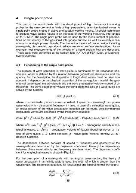
4. Single point probe
4. Single point probe
4. Single point probe

Create successful ePaper yourself
Turn your PDF publications into a flip-book with our unique Google optimized e-Paper software.
<strong>4.</strong> <strong>Single</strong> <strong>point</strong> <strong>probe</strong><br />
This part of the report deals with the development of high frequency immersing<br />
<strong>probe</strong>s for the measurement in fluids of high parameters, using longitudinal waves. A<br />
single <strong>point</strong> <strong>probe</strong> is used in active and passive working modes. A special technology<br />
to produce wave-guides results in an increase of the working frequency into ranges<br />
up to 10 MHz. The single <strong>point</strong> <strong>probe</strong> can be used for the measurement of gas fractions<br />
or the velocity of the gas-liquid inter-phase surface as well as velocity measurements<br />
in single phased liquids. The theoretical basics of <strong>probe</strong> design including<br />
wave-guide, piezoelectric crystal and radiating-receiving surface are described. As an<br />
example, test measurements of the velocity of a liquid sodium flow are described.<br />
These tests were performed at the sodium loop NATAN of FZR (Dept. of Magnetohydrodynamics).<br />
<strong>4.</strong>1 Functioning of the single <strong>point</strong> <strong>probe</strong><br />
The process of wave spreading in wave-guide is dominated by the resonance phenomena,<br />
which is defined by the relation between geometrical dimensions and frequency.<br />
For the description, the dispersion of longitudinal waves must be taken into<br />
account. It depends on the physical properties of the wave-guide material, the geometrical<br />
parameters, the wavelength and the wave propagation velocity (speed of ultrasound).<br />
The wave equation for waves travelling along the axis of a wave-guide are<br />
solved by the function:<br />
exp [ j( γz-ωt ) ], (<strong>4.</strong>1)<br />
where: z - coordinate; γ = 2π/λ = ω/c - constant of speed; λ - wavelength; c - phase<br />
wave velocity; ω - ultrasound frequency; t - time. In case of a cylindrical wave-guide,<br />
an exact solution of the wave propagation equation can be found. Axis-symmetrical<br />
longitudinal waves are described by the Pohgamer equation:<br />
2α/a ( β 2 + γ 2 ) J 1 (α a)J 1 (βa) -(β 2 -γ 2 ) 2 J 0 (α a) J 1 (βa) - 4γαβ J 1 (α a) J 0 (βa) = 0 (<strong>4.</strong>2)<br />
where: α 2 = (ω/c l ) 2 -γ 2 ; β 2 = (ω/c τ )-γ 2 ; c l = ( 2 µ + λ / ρ - propagation velocity of longitudinal<br />
waves; c τ = µ ρ - propagation velocity of flexural (bending) waves; a - radius<br />
of wave-guide; µ, λ- Lame constant; ρ - wave-guide material density; J 0 , J 1 -<br />
Bessel’s functions.<br />
The dependence between constant of spread γ, frequency and geometry of the<br />
wave-guide are determined by the dispersion coefficient. Thereby the dependency<br />
between phase wave velocity and frequency are determined. The dispersion coefficient<br />
for longitudinal waves is shown in Fig. <strong>4.</strong>1.<br />
For the description of a wave-guide with rectangular cross-section, the theory of<br />
wave propagation in an infinite plate is used, the width of which is greater than the<br />
wavelength. The dispersion equations for longitudinal and flexural normal waves are:<br />
<br />
WKMβK<br />
γ<br />
αβ<br />
= −<br />
<br />
WKMαK<br />
γ<br />
− β <br />
35<br />
<br />
; (<strong>4.</strong>3)
WKMβK<br />
γ<br />
− β <br />
= −<br />
<br />
WKαK<br />
γ<br />
αβ<br />
<br />
. (<strong>4.</strong>4)<br />
Where, h is the thickness of<br />
the plate.<br />
Graphs of the dispersion of C l /C<br />
longitudinal and flexural<br />
waves in endless plates are<br />
presented in Fig. <strong>4.</strong>2. The<br />
behaviour of dispersion lines<br />
for the plate and for cylindrical<br />
wave-guides are analogous.<br />
A maximum of dispersion<br />
(the dependence velocity<br />
of acoustical waves from<br />
frequency) in field of low frequency<br />
is observed. For the<br />
2hf/C l<br />
bad waves of higher order,<br />
attenuation is increased after<br />
Fig. <strong>4.</strong>1 Dispersion of longitudinal waves<br />
increasing the cross-section<br />
size and the working frequency.<br />
Beginning from a L 0, L 1 , L 2 - longitudinal waves of 0, 1, 2 orders<br />
certain working frequency, C l – velocity of longitudinal wave in fine rod<br />
the quantity and direction of<br />
the irradiated energy is increased in comparison to a cylindrical wave-guide.<br />
<strong>4.</strong>2 Design of coiled wave-guide sensor<br />
An infinite plate has some advantages<br />
in the region of high<br />
frequency. Therefore, a new type<br />
of wave-guide was developed.<br />
The so-called coiled wave-guide<br />
consists of a thin foil of stainless<br />
steel, which is wrapped to form a<br />
cylindrical rod of a certain diameter<br />
much larger than the<br />
thickness of the foil. The latter<br />
approximately equals the wavelength.<br />
The acoustic sensor on<br />
basis of such a coiled waveguide<br />
is shown in Fig. <strong>4.</strong>3. Each<br />
layer of foil forms an individual<br />
wave-guide, which works independently<br />
from the other layers.<br />
The waves are in phase, the irradiated<br />
acoustical energy is a result<br />
of a positive superposition of<br />
the waves in each layer.<br />
c l /c<br />
3.0<br />
2.0<br />
36<br />
L 0<br />
F 0 F 1 L 1<br />
0 0.5 2hf/c l<br />
Fig. <strong>4.</strong>2 Dispersion of the wave propagation velocity<br />
in an endless plate of 0.3 mm thickness<br />
F 0 , F 1 -bending wave; L 0 , L 1 -longitudinal wave
For effective radiation into the measuring<br />
fluid, the radiating surface is<br />
formed by a large number of layers.<br />
For the hermetisation of the <strong>probe</strong>,<br />
the immersed part of the wave-guide<br />
is put into a protective top and fixed<br />
with the top by welding. In order to<br />
protect it from mechanical damage,<br />
the <strong>probe</strong> is placed into a protective<br />
case. The main technical characteristics<br />
of the single <strong>point</strong> <strong>probe</strong> are<br />
shown in Fig. <strong>4.</strong><strong>4.</strong> The main parameters<br />
are: maximum of working<br />
temperature - 400<br />
0 C; maximum<br />
pressure 15 MPa; material of waveguide<br />
- steel 08CrNiTi18.10; diameter<br />
of wave-guide - 7 mm; working frequency<br />
- 4 MHz; angle of radiation -<br />
90 0 ; angle of beam widening - 1.7 0 ;<br />
near area - 25 mm; attenuation coefficient<br />
in the electric-acoustical line -<br />
7. The sensor is calibrated in impulse<br />
mode.<br />
<strong>4.</strong>3 Example of application<br />
The single <strong>point</strong> <strong>probe</strong> was connected<br />
to an ultrasonic test monitor of<br />
the SONY company and tested in reflection<br />
mode. The velocity profile of<br />
a liquid sodium flow was measured in<br />
the sodium loop NATAN. Previously,<br />
the main characteristic of single <strong>point</strong><br />
<strong>probe</strong> were determined in a water<br />
flow in the laboratory of TUNN. After<br />
that, the single <strong>point</strong> <strong>probe</strong> was<br />
mounted into the sodium circuit of<br />
Rossendorf. It was placed into the<br />
test channel under an angle of 70 0 to<br />
the axis of the cross-section. The working temperature of the liquid sodium was<br />
200 0 C. The velocity of liquid sodium was varied in range from 0.2 to 1.0 m/s. Some<br />
experimental data of velocity profile variations in the cross-section of the channel are<br />
showed in Fig. <strong>4.</strong>5.<br />
<strong>4.</strong>4 Conclusions<br />
Fig. <strong>4.</strong>3<br />
Design of single <strong>point</strong> <strong>probe</strong> with<br />
coiled wave-guide<br />
1 - case; 2 - radiation area; 3 - protective top; 4 -<br />
wave-guide; 5 - distance element; 6 - rubber-plug;<br />
7 - connector; 8 - acoustic converter<br />
The new type of coiled wave-guide allows to design sensors, which can work on a<br />
higher frequency, than traditional wave-guide sensors. This is an important result for<br />
non-intrusive high-temperature applications, where a direct mounting of the piezoelectric<br />
crystal to the surface of the experimental or industrial facility is not possible.<br />
37
δ<br />
a<br />
10 20 30 40 [mm]<br />
Fig. <strong>4.</strong>4<br />
Acoustical beam shape of the single <strong>point</strong> <strong>probe</strong><br />
Velocity [m/s]<br />
Depth [mm]<br />
Fig. <strong>4.</strong>5 Measured velocity profile at the FZR sodium loop<br />
38