Online Full Text - International Association of Engineers
Online Full Text - International Association of Engineers
Online Full Text - International Association of Engineers

You also want an ePaper? Increase the reach of your titles
YUMPU automatically turns print PDFs into web optimized ePapers that Google loves.
Proceedings <strong>of</strong> the World Congress on Engineering and Computer Science 2013 Vol II<br />
WCECS 2013, 23-25 October, 2013, San Francisco, USA<br />
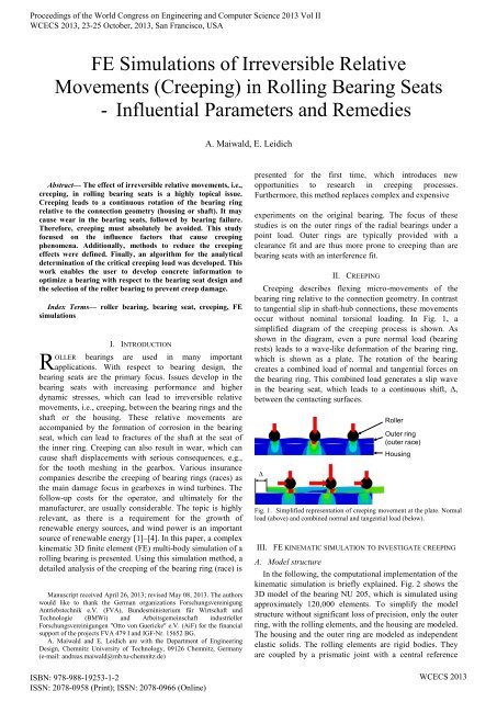
FE Simulations <strong>of</strong> Irreversible Relative<br />
Movements (Creeping) in Rolling Bearing Seats<br />
- Influential Parameters and Remedies<br />
A. Maiwald, E. Leidich<br />
<br />
Abstract— The effect <strong>of</strong> irreversible relative movements, i.e.,<br />
creeping, in rolling bearing seats is a highly topical issue.<br />
Creeping leads to a continuous rotation <strong>of</strong> the bearing ring<br />
relative to the connection geometry (housing or shaft). It may<br />
cause wear in the bearing seats, followed by bearing failure.<br />
Therefore, creeping must absolutely be avoided. This study<br />
focused on the influence factors that cause creeping<br />
phenomena. Additionally, methods to reduce the creeping<br />
effects were defined. Finally, an algorithm for the analytical<br />
determination <strong>of</strong> the critical creeping load was developed. This<br />
work enables the user to develop concrete information to<br />
optimize a bearing with respect to the bearing seat design and<br />
the selection <strong>of</strong> the roller bearing to prevent creep damage.<br />
Index Terms— roller bearing, bearing seat, creeping, FE<br />
simulations<br />
R<br />
I. INTRODUCTION<br />
OLLER bearings are used in many important<br />
applications. With respect to bearing design, the<br />
bearing seats are the primary focus. Issues develop in the<br />
bearing seats with increasing performance and higher<br />
dynamic stresses, which can lead to irreversible relative<br />
movements, i.e., creeping, between the bearing rings and the<br />
shaft or the housing. These relative movements are<br />
accompanied by the formation <strong>of</strong> corrosion in the bearing<br />
seat, which can lead to fractures <strong>of</strong> the shaft at the seat <strong>of</strong><br />
the inner ring. Creeping can also result in wear, which can<br />
cause shaft displacements with serious consequences, e.g.,<br />
for the tooth meshing in the gearbox. Various insurance<br />
companies describe the creeping <strong>of</strong> bearing rings (races) as<br />
the main damage focus in gearboxes in wind turbines. The<br />
follow-up costs for the operator, and ultimately for the<br />
manufacturer, are usually considerable. The topic is highly<br />
relevant, as there is a requirement for the growth <strong>of</strong><br />
renewable energy sources, and wind power is an important<br />
source <strong>of</strong> renewable energy [1]–[4]. In this paper, a complex<br />
kinematic 3D finite element (FE) multi-body simulation <strong>of</strong> a<br />
rolling bearing is presented. Using this simulation method, a<br />
detailed analysis <strong>of</strong> the creeping <strong>of</strong> the bearing ring (race) is<br />
Manuscript received April 26, 2013; revised May 08, 2013. The authors<br />
would like to thank the German organizations Forschungsvereinigung<br />
Antriebstechnik e.V. (FVA), Bundesministerium für Wirtschaft und<br />
Technologie (BMWi) and Arbeitsgemeinschaft industrieller<br />
Forschungsvereinigungen "Otto von Guericke" e.V. (AiF) for the financial<br />
support <strong>of</strong> the projects FVA 479 I and IGF-Nr. 15652 BG.<br />
A. Maiwald and E. Leidich are with the Department <strong>of</strong> Engineering<br />
Design, Chemnitz University <strong>of</strong> Technology, 09126 Chemnitz, Germany<br />
(e-mail: andreas.maiwald@mb.tu-chemnitz.de)<br />
ISBN: 978-988-19253-1-2<br />
ISSN: 2078-0958 (Print); ISSN: 2078-0966 (<strong>Online</strong>)<br />
presented for the first time, which introduces new<br />
opportunities to research in creeping processes.<br />
Furthermore, this method replaces complex and expensive<br />
experiments on the original bearing. The focus <strong>of</strong> these<br />
studies is on the outer rings <strong>of</strong> the radial bearings under a<br />
point load. Outer rings are typically provided with a<br />
clearance fit and are thus more prone to creeping than are<br />
bearing seats with an interference fit.<br />
II. CREEPING<br />
Creeping describes flexing micro-movements <strong>of</strong> the<br />
bearing ring relative to the connection geometry. In contrast<br />
to tangential slip in shaft-hub connections, these movements<br />
occur without nominal torsional loading. In Fig. 1, a<br />
simplified diagram <strong>of</strong> the creeping process is shown. As<br />
shown in the diagram, even a pure normal load (bearing<br />
rests) leads to a wave-like deformation <strong>of</strong> the bearing ring,<br />
which is shown as a plate. The rotation <strong>of</strong> the bearing<br />
creates a combined load <strong>of</strong> normal and tangential forces on<br />
the bearing ring. This combined load generates a slip wave<br />
in the bearing seat, which leads to a continuous shift, Δ,<br />
between the contacting surfaces.<br />
Δ<br />
III. FE KINEMATIC SIMULATION TO INVESTIGATE CREEPING<br />
A. Model structure<br />
Roller<br />
Outer ring<br />
(outer race)<br />
Housing<br />
Fig. 1. Simplified representation <strong>of</strong> creeping movement at the plate. Normal<br />
load (above) and combined normal and tangential load (below).<br />
In the following, the computational implementation <strong>of</strong> the<br />
kinematic simulation is briefly explained. Fig. 2 shows the<br />
3D model <strong>of</strong> the bearing NU 205, which is simulated using<br />
approximately 120,000 elements. To simplify the model<br />
structure without significant loss <strong>of</strong> precision, only the outer<br />
ring, with the rolling elements, and the housing are modeled.<br />
The housing and the outer ring are modeled as independent<br />
elastic solids. The rolling elements are rigid bodies. They<br />
are coupled by a prismatic joint with a central reference<br />
WCECS 2013
d<br />
Proceedings <strong>of</strong> the World Congress on Engineering and Computer Science 2013 Vol II<br />
WCECS 2013, 23-25 October, 2013, San Francisco, USA<br />
point (Fig. 3). Thus, each rolling element has only one<br />
degree <strong>of</strong> freedom in the radial direction. This radial degree<br />
<strong>of</strong> freedom is eliminated by the loads <strong>of</strong> the rolling<br />
elements, which can be calculated according to DIN ISO<br />
281 [5]. By rotation <strong>of</strong> the reference point, the rolling<br />
elements move circumferentially and slide frictionless over<br />
the contact surface <strong>of</strong> the outer ring. For all simulations<br />
(unless otherwise specified) the coefficient <strong>of</strong> friction in the<br />
bearing seat is set to µ = 0.3. This value corresponds to oillubricated<br />
steel-steel contact (100Cr6 E vs. 42CrMo4 +QT)<br />
after the “running-in phase”, and has been determined<br />
experimentally in [3].<br />
A detailed description <strong>of</strong> the complete simulation<br />
methodology can be found in [4]. For the FE analysis,<br />
version 6.10-3 <strong>of</strong> the ABAQUS s<strong>of</strong>tware was used.<br />
C. Reference geometry<br />
Fig. 5 shows all geometric parameters for the simulation<br />
results presented below.<br />
d O<br />
d o = d I = d J<br />
d o = d I<br />
d i<br />
b<br />
F r<br />
Housing<br />
Outer ring<br />
Roller<br />
Inner ring<br />
Shaft<br />
Fugendruck<br />
[MPa]<br />
Fig. 5. Geometric parameters and definition <strong>of</strong> joint diameter, d J.<br />
Housing<br />
Gehäuse<br />
Rollers<br />
Rollen<br />
Outer ring<br />
(Outer race)<br />
Außenring<br />
F = 10 kN; u = 0,25 ‰; µ =0,15<br />
The thickness ratio, Q, <strong>of</strong> the inner and the outer diameter<br />
is used to describe the wall thickness <strong>of</strong> the cylindrical<br />
components as follows:<br />
d<br />
d<br />
i<br />
I<br />
Q b<br />
, Q<br />
h<br />
d<br />
o<br />
d<br />
(1)<br />
O<br />
Fig. 2. Model <strong>of</strong> the simulated bearing NU 205.<br />
Fig. 3. Substitution <strong>of</strong> the cage.<br />
B. Analysis <strong>of</strong> creeping data<br />
Roller with<br />
reference point<br />
Prismatic joint<br />
Central<br />
reference point<br />
The creeping torque, T C , is evaluated to measure the<br />
intensity <strong>of</strong> creeping in the simulated bearing ring. This<br />
parameter describes the torque in the circumferential<br />
direction, which is needed to prevent the macroscopic<br />
relative movement (creeping) between the housing and the<br />
bearing ring (Fig. 4). A high creeping torque corresponds to<br />
a large creeping intensity <strong>of</strong> the bearing ring and is therefore<br />
classified as negative and converse.<br />
F r<br />
<br />
F C<br />
T<br />
C<br />
d<br />
FC<br />
<br />
2<br />
Housing<br />
Roller<br />
To characterize the interference, or clearance fit, it is<br />
normalized by the joint diameter, d J . By definition, the<br />
normalized clearance fit, ξ*, has negative values and is<br />
expressed as follows:<br />
ξ<br />
d<br />
ξ<br />
(2)<br />
d<br />
J<br />
The bearing load is divided by the projected surface area<br />
<strong>of</strong> the bearing seat, A proj . This results in the surface areanormalized<br />
radial load, p r , as follows:<br />
p<br />
F<br />
A<br />
r<br />
r<br />
, where<br />
proj o<br />
Aproj<br />
b d , (3)<br />
which is analogous to the bearing stress.<br />
IV. VALIDATION OF THE FE-KINEMATIC SIMULATION<br />
Using the current FE model, creeping movements are<br />
realistically simulated with the aid <strong>of</strong> FEM for the first time.<br />
The simulation results correlate with the experimental data<br />
[3]–[6]. This is demonstrated by the comparison <strong>of</strong><br />
experimental and simulated results shown in Fig. 6. Thus,<br />
the simulation enables the user to perform extensive<br />
parameter variations to investigate the effects <strong>of</strong> creeping,<br />
which were not previously possible. Thus, the use <strong>of</strong> costintensive<br />
experiments is no longer necessary.<br />
Outer ring<br />
Fig. 4. Model for the determination <strong>of</strong> the creeping force, F C, with respect<br />
to the creeping torque, T C.<br />
ISBN: 978-988-19253-1-2<br />
ISSN: 2078-0958 (Print); ISSN: 2078-0966 (<strong>Online</strong>)<br />
WCECS 2013
Creeping torque T C [Nm]<br />
Creeping torque T C [Nm]<br />
Reference<br />
E-Modulus<br />
Housing wall<br />
thickness<br />
Coefficient <strong>of</strong><br />
friction<br />
Creeping torque T C [Nm]<br />
Reference<br />
Normalized<br />
radial load<br />
Outer ring<br />
wall thickness<br />
Number<br />
<strong>of</strong> rollers<br />
Proceedings <strong>of</strong> the World Congress on Engineering and Computer Science 2013 Vol II<br />
WCECS 2013, 23-25 October, 2013, San Francisco, USA<br />
16<br />
14<br />
12<br />
10<br />
8<br />
F r<br />
ω<br />
3D-FEM<br />
As expected, a higher coefficient <strong>of</strong> friction in the bearing<br />
seat leads to a reduction <strong>of</strong> the creeping torque. Therefore,<br />
arrangements to increase the coefficient <strong>of</strong> friction (surface<br />
coating, etc.) are recommended. Possible solutions are<br />
presented in [7].<br />
6<br />
4<br />
E-modulus 210 GPa<br />
2<br />
0<br />
-0.2 -0.4 -0.6<br />
Normalized clearance fit ξ* [‰]<br />
Experiment<br />
Outer ring<br />
Housing<br />
E-modulus 210 GPa<br />
E-modulus 70 GPa<br />
Fig. 6. Comparison <strong>of</strong> the creeping torque between 3D FE simulation and<br />
experiment for the example <strong>of</strong> the normalized clearance fit, ξ*, between the<br />
housing and the outer ring. (Reference data: Bearing NU 205; normalized<br />
radial load, p r = 18 MPa; coefficient <strong>of</strong> friction between the outer ring and<br />
housing, µ = 0.3; elastic modulus <strong>of</strong> the housing, E = 210 GPa)<br />
V. PARAMETER ANALYSIS OF THE CREEPING BEHAVIOR OF<br />
ROLLER BEARINGS FOR THE EXAMPLE OF THE OUTER RING OF<br />
THE CYLINDRICAL ROLLER BEARING NU 205<br />
A. Influence <strong>of</strong> the bearing housing<br />
In Fig. 7, the influence <strong>of</strong> the bearing housing on the<br />
creeping behavior by changing the modulus <strong>of</strong> elasticity, E,<br />
the thickness ratio, Q h with respect to the housing stiffness<br />
and the coefficient <strong>of</strong> friction between the outer ring and the<br />
housing µ is illustrated.<br />
14<br />
12<br />
10<br />
8<br />
6<br />
4<br />
2<br />
E=<br />
140 GPa<br />
E=<br />
70 GPa<br />
Q h =0.79<br />
Q h =0.87<br />
µ=0.15<br />
µ=0.4<br />
Fig. 8. Qualitative representation <strong>of</strong> the absorption <strong>of</strong> the bearing ring<br />
deformation under normal load conditions by varying the housing stiffness<br />
through the modulus <strong>of</strong> elasticity, E.<br />
B. Influence <strong>of</strong> the bearing parameters<br />
Fig. 9 shows the influence <strong>of</strong> the bearing parameters on<br />
the creeping behavior by comparing the results with<br />
different thickness ratios <strong>of</strong> the outer ring, Q b , numbers <strong>of</strong><br />
rollers, Z, and surface area-normalized radial loads, p r .<br />
18<br />
16<br />
14<br />
12<br />
10<br />
8<br />
6<br />
4<br />
2<br />
0<br />
p r =<br />
13 MPa<br />
p r =<br />
20 MPa<br />
Q b =0.95<br />
Q b =0.85<br />
Z=11<br />
Z=15<br />
Fig. 9. Change <strong>of</strong> the creeping torque with variations <strong>of</strong> the thickness ratio<br />
<strong>of</strong> the outer ring, Q b, the number <strong>of</strong> rollers, Z, and the surface areanormalized<br />
radial load, p r. (Reference data: Bearing NU 205; p r = 18 MPa;<br />
coefficient <strong>of</strong> friction in the bearing seat, µ = 0.3; normalized clearance fit,<br />
ξ* = -0.4 ‰; modulus <strong>of</strong> elasticity <strong>of</strong> the housing, E = 210 GPa; Z = 13;<br />
Q b = 0.90)<br />
0<br />
Fig. 7. Change <strong>of</strong> the creeping torque from variations in the modulus <strong>of</strong><br />
elasticity <strong>of</strong> the housing, E, the housing wall thickness, Q h and the<br />
coefficient <strong>of</strong> friction between the outer ring and the housing, µ. (Reference<br />
data: Bearing NU 205; normalized radial load, p r = 18 MPa; µ = 0.3;<br />
normalized clearance fit, ξ* = -0.4 ‰; E = 210 GPa; Q h = 0.69)<br />
The results show that with a decreasing modulus <strong>of</strong><br />
elasticity, E, the creeping torque, T C , decreases also. This is<br />
because a s<strong>of</strong>ter housing is better able to absorb the creeping<br />
motion <strong>of</strong> the bearing ring (Fig. 8). Thus, the bearing seat<br />
area between two loaded rolling elements (see Fig. 1) is<br />
exposed to a local contact pressure increase. Therefore, in<br />
this creeping-critical bearing seat area (see Chapter 2),<br />
higher local contact shear stresses are transferable, which<br />
leads to a reduction or prevention <strong>of</strong> creeping <strong>of</strong> the bearing<br />
ring. Through the implementation <strong>of</strong> elastic thin-walled<br />
housing structures (lower housing wall thickness), the<br />
torque is only marginally reduced. The influence <strong>of</strong> the<br />
modulus <strong>of</strong> elasticity, in contrast to the housing wall<br />
thickness, is much higher.<br />
The results show that thick bearing rings (Q b = 0.85) have<br />
less inclination to creep than thin because <strong>of</strong> the increased<br />
stiffness <strong>of</strong> thick-walled bearing rings. The thick-walled<br />
bearing ring deforms less (see Chapter 2), and the creeping<br />
process is inhibited.<br />
In addition, reduction <strong>of</strong> the radial load leads to a<br />
decrease in the creeping torque. This relation is based on the<br />
fundamental processes <strong>of</strong> creeping, i.e., creeping occurs<br />
primarily from the formation <strong>of</strong> slip in the bearing seat as a<br />
result <strong>of</strong> the tangential deformation <strong>of</strong> the loaded bearing<br />
ring (see Chapter 2). If the load is small, the tangential<br />
deformation and, thus, the creeping torque are also small.<br />
Fig. 9 also shows that the increase in the number <strong>of</strong> rollers,<br />
with an identical bearing load, results in a decreased<br />
creeping torque. This is because <strong>of</strong> reduced roller loads,<br />
which reduces the tangential deformation <strong>of</strong> the bearing<br />
ring.<br />
ISBN: 978-988-19253-1-2<br />
ISSN: 2078-0958 (Print); ISSN: 2078-0966 (<strong>Online</strong>)<br />
WCECS 2013
Creeping torque T C [Nm]<br />
Reference<br />
s<br />
Proceedings <strong>of</strong> the World Congress on Engineering and Computer Science 2013 Vol II<br />
WCECS 2013, 23-25 October, 2013, San Francisco, USA<br />
C. Influence <strong>of</strong> the fit<br />
In Fig. 10 the effect <strong>of</strong> the normalized interference fit, ξ,<br />
and clearance fit, ξ*, between housing and outer ring on the<br />
creeping behavior is shown. The results show that an<br />
increase <strong>of</strong> the normalized clearance fit, ξ * = -0.1 ‰<br />
to -0.6 ‰ results in a reduction <strong>of</strong> the creeping torque.<br />
Wall thickness <strong>of</strong><br />
the bearing ring<br />
Number <strong>of</strong> rollers .<br />
Influences Abhil on creeping<br />
Bearing<br />
Housing / Shaft<br />
E-modulus<br />
Interference fit<br />
20<br />
NU205<br />
p r = 18 MPa / µ F = 0.3 / E = 210 GPa<br />
Bearing clearance<br />
Bending <strong>of</strong><br />
the shaft<br />
15<br />
Radial load<br />
Wall thickness <strong>of</strong><br />
the housing/shaft<br />
10<br />
5<br />
Axial load<br />
breadth <strong>of</strong><br />
the bearing ring<br />
=<br />
=<br />
Raise value<br />
Reduce creeping<br />
Reduce value<br />
Reduce creeping<br />
Fig. 12. Effects <strong>of</strong> relevant bearing parameters on creeping [4].<br />
0<br />
-0.6 -0.5 -0.4 -0.3 -0.2 -0.1 0 0.1<br />
ξ* [‰] ξ [‰]<br />
Normalized fit<br />
Fig. 10. Change <strong>of</strong> the creeping torque from a variation <strong>of</strong> the normalized<br />
clearance fit (ξ* < 0) and the normalized interference fit (ξ ≥ 0) between the<br />
housing and the outer ring.<br />
In [3] and [6], this creeping behavior is verified<br />
experimentally. The effect <strong>of</strong> the clearance fit can be<br />
explained by the modification <strong>of</strong> the load zone (Fig. 11).<br />
Increasing the clearance fit (and/or the bearing clearance)<br />
leads to a reduction <strong>of</strong> the load zone, i.e., fewer rollers are<br />
used to transfer the bearing load. The load transfer is thus<br />
based on a smaller contact surface area and a higher contact<br />
pressure, thus increasing the transferable local contact shear<br />
stress. The reduction in stress leads to a reduction in or the<br />
prevention <strong>of</strong> creeping.<br />
-<br />
Bearing clearance<br />
&<br />
Clearance fit<br />
+<br />
F r<br />
F r<br />
VI. ADDITIONAL CONSTRUCTIVE CAPABILITIES TO REDUCE<br />
CREEPING<br />
A. Flexible thin-film interlayer (FTI)<br />
As a possible remedy against walking (based on the<br />
results presented in Chapter 4, i.e., that the creeping moment<br />
decreases by a reduction in the modulus <strong>of</strong> elasticity), a<br />
flexible thin-film interlayer (FTI) between the housing and<br />
the bearing ring was simulated (Fig. 13). The housing is<br />
made <strong>of</strong> a partitioned continuum representing the two<br />
material areas <strong>of</strong> FTI and regular housing material. Thus, the<br />
contact surfaces between FTI and housing are neglected,<br />
which would correspond to bonding <strong>of</strong> the contact materials.<br />
The simulation results presented in Fig. 14 show that as<br />
the modulus <strong>of</strong> elasticity <strong>of</strong> the FTI decreases, the creeping<br />
torque also decreases. With the use <strong>of</strong> polyamide, the<br />
reduction can be as large as 40%. The opposite trend for the<br />
polyamide-FTI with the larger wall thickness, s = 300 µm<br />
(compared to s = 200 µm), is due to the reduced tangential<br />
stiffness for the thicker FTI. The polyamide is strongly<br />
deformed by the operating loads, and as a result <strong>of</strong> the<br />
model structure (locking <strong>of</strong> the outer ring in the<br />
circumferential direction, cf. Fig. 4), the creeping torque<br />
increases.<br />
The simulation <strong>of</strong> magnesium as the FTI material shows the<br />
limitations <strong>of</strong> the FTI, achieving only a marginal reduction<br />
<strong>of</strong> the creeping torque.<br />
Big<br />
load zone<br />
Small<br />
load zone<br />
Fig. 11. Different load zones in reliance to the clearance fit.<br />
D. Other important parameters<br />
In addition to the parameter analysis presented, other<br />
influences on creeping were determined in [4] and [8].<br />
Those studies developed recommendations for bearing seat<br />
design. An overview <strong>of</strong> those solutions is shown in Fig. 12.<br />
Housing<br />
FTI<br />
E-Modulus <strong>of</strong> the FTI<br />
Bearing<br />
Shaft<br />
Material<br />
E FTI [GPa]<br />
Magnesium 42<br />
Polyamide 4<br />
Fig. 13. Schematic diagram <strong>of</strong> the FTI (left) and the material<br />
characteristics <strong>of</strong> the FTI (right).<br />
ISBN: 978-988-19253-1-2<br />
ISSN: 2078-0958 (Print); ISSN: 2078-0966 (<strong>Online</strong>)<br />
WCECS 2013
Creeping Torque T C [Nm]<br />
Creeping torque T C [Nm]<br />
Without FTI<br />
s = 100 µm<br />
Magnesium<br />
s = 200<br />
s = 300 µm<br />
s = 100 µm<br />
Polyamide<br />
s = 200<br />
s = 300 µm<br />
Proceedings <strong>of</strong> the World Congress on Engineering and Computer Science 2013 Vol II<br />
WCECS 2013, 23-25 October, 2013, San Francisco, USA<br />
14<br />
12<br />
10<br />
8<br />
6<br />
4<br />
2<br />
0<br />
B. Form-fitted creeping lock<br />
F r<br />
ω<br />
Fig. 14. Comparison <strong>of</strong> the creeping torque for varying wall thickness, s,<br />
and material properties <strong>of</strong> the FTI. (Reference data: Bearing NU 205;<br />
normalized radial load, p r = 18 MPa; coefficient <strong>of</strong> friction in the bearing<br />
seat, µ = 0.3; normalized clearance fit, ξ* = -0.4 ‰; modulus <strong>of</strong> elasticity<br />
<strong>of</strong> the housing, E = 210 GPa)<br />
For heavily loaded bearings and critical creeping<br />
applications, a form-fitted connection between the bearing<br />
ring and the housing, including the shaft, is essential. Fig. 15<br />
shows the circumferential forces between the outer ring and<br />
the housing, which must be absorbed by a form-fitted<br />
creeping lock. It were researched a rigid element (the<br />
reference) and two elastic spring elements. Each spring<br />
element can be described by a linear spring characteristic<br />
curve, which is defined by a spring rate, c = F W /Δl. The<br />
spring deflection, Δl, is thus equivalent to the relative<br />
movement between the housing and the outer ring (global<br />
slip). The results show that a s<strong>of</strong>t form-fitted creeping lock<br />
has to take substantially lower loads than a rigid one.<br />
Further studies on the subject are part <strong>of</strong> the ongoing<br />
German research project Abhilfemaßnahmen Wandern<br />
(remedies for creeping) [9].<br />
14<br />
12<br />
10<br />
8<br />
6<br />
4<br />
0 0.2 0.4 0.6 0.8 1<br />
Rotations <strong>of</strong> the shaft [-]<br />
VII. CALCULATION METHODS TO DETERMINE THE CRITICAL<br />
CREEPING LOAD<br />
A fundamental goal for the practical implementation <strong>of</strong><br />
the results is the development and verification <strong>of</strong> a<br />
calculation model to determine the critical creeping load <strong>of</strong> a<br />
bearing. The model should provide a rough estimate <strong>of</strong> the<br />
d<br />
T<br />
F r<br />
C<br />
l<br />
c<br />
d<br />
FC<br />
<br />
2<br />
Reference (c→∞)<br />
c=10000 [N/mm]<br />
c=500 [N/mm]<br />
Fig. 15. Creeping torque as a function <strong>of</strong> the elasticity <strong>of</strong> the form-fitted<br />
creeping lock between the outer ring and the housing. (Reference data:<br />
Bearing NU 205; normalized radial load, p r = 18 MPa; coefficient <strong>of</strong><br />
friction in the bearing seat, µ = 0.3; normalized clearance fit, ξ* = -0.4 ‰;<br />
modulus <strong>of</strong> elasticity <strong>of</strong> the housing, E = 210 GPa)<br />
ω<br />
F C<br />
bearing load when approaching the onset <strong>of</strong> creeping.<br />
Implementation <strong>of</strong> this model can thus limit the usage <strong>of</strong><br />
complex, computationally intensive 3D FE simulations in<br />
bearing design. The following algorithm is used to calculate<br />
the critical creeping load for the outer ring <strong>of</strong> roller bearings<br />
under radial loads. It states that creeping starts when a loadinduced<br />
slip zone extends over the entire width <strong>of</strong> the<br />
bearing ring. Unfortunately, slip cannot be calculated using<br />
analytical equations. Therefore, the calculation <strong>of</strong> the<br />
inception <strong>of</strong> slip is done with the radial stress (σ rr (F i ,φ)) and<br />
shear stress (τ(F i ,φ)) acting on the bearing seat as follows<br />
(Eqs. 4 and 5 from [10]):<br />
<br />
2 2<br />
r D cos φ <br />
2 D cos φ r<br />
<br />
<br />
2<br />
F<br />
D r 1<br />
cos φ<br />
<br />
<br />
i <br />
σ<br />
rr( F<br />
i<br />
,φ ) <br />
<br />
2 2<br />
2<br />
πb<br />
r D 2 D r cos φ<br />
<br />
(4)<br />
<br />
<br />
5 ν cos φ 3 ν cos φ D<br />
<br />
4 r 4 r 2 r<br />
<br />
2 <br />
D<br />
<br />
3 2<br />
<br />
2 D sin r D cos D r cos<br />
<br />
<br />
2 2<br />
F 2 <br />
i r D 2 D r cos<br />
( F<br />
i<br />
, ) <br />
<br />
(5)<br />
b <br />
<br />
1 sin 2 3 sin<br />
D <br />
<br />
<br />
3<br />
4 r 4 r <br />
Based on Eqs. 4 and 5, the total stress from a single roller<br />
force is then added by angular transformation to the total<br />
stresses <strong>of</strong> the other individual roller forces (all forces<br />
together reflect the bearing load, as shown in Fig. 16) as<br />
follows:<br />
σ( F ,φ) σ( F ,φ)<br />
(6)<br />
r<br />
Fictitious joint<br />
Thickness b<br />
Single roller load<br />
F i<br />
ØD<br />
i<br />
<br />
Finally, using the generalized Coulomb friction law, the<br />
transferable local shear stresses in the bearing seat, τ tr (F i ,φ),<br />
are calculated as follows:<br />
( F , ) µ ( F , )<br />
(7)<br />
tr r F rr r<br />
r<br />
Fictitious joint<br />
Thickness b<br />
To ensure a creeping-safe bearing, the transferable local<br />
shear stresses, τ tr (F i ,φ), must not be exceeded by the local<br />
shear stresses, τ(F i ,φ), over the complete circumference.<br />
<br />
F i<br />
<br />
<br />
<br />
Combined roller loads<br />
Fig. 16. Mechanical model (circular hole in an infinite plate) for the outer<br />
ring <strong>of</strong> a radially loaded bearing [4].<br />
ISBN: 978-988-19253-1-2<br />
ISSN: 2078-0958 (Print); ISSN: 2078-0966 (<strong>Online</strong>)<br />
WCECS 2013
Proceedings <strong>of</strong> the World Congress on Engineering and Computer Science 2013 Vol II<br />
WCECS 2013, 23-25 October, 2013, San Francisco, USA<br />
The safety against creeping, S C , is also included in the<br />
calculation as follows:<br />
tr<br />
( Fr<br />
, )<br />
( Fr<br />
, ) <br />
(8)<br />
S<br />
C<br />
This calculation model, along with other algorithms<br />
(calculation <strong>of</strong> the inner ring and <strong>of</strong> the creeping torque),<br />
have been programmed by the German research association<br />
Forschungsvereinigung Antriebstechnik e.V. (FVA). As a<br />
result, the fully automated calculation tool, SimWag, is<br />
available, which enables the user to construct bearing seats<br />
without creeping.<br />
VIII. SUMMARY<br />
In this paper, numerical analyses <strong>of</strong> the creeping behavior<br />
<strong>of</strong> roller bearings are presented. With the aid <strong>of</strong> various<br />
complex 3D finite element kinematic simulations, the<br />
creeping mechanism is determined. Creeping describes<br />
flexing micro-movements (slip) <strong>of</strong> the loaded bearing ring.<br />
This slip leads to a substantial continuous rotation <strong>of</strong> the<br />
bearing ring relative to the connection geometry (housing or<br />
shaft). Through the studies performed, important influencing<br />
parameters are detected that cause or encourage creeping.<br />
Furthermore, approaches for geometric and constructive<br />
remedies for reducing or eliminating creeping are discussed.<br />
Finally, an algorithm for the analytical determination <strong>of</strong> the<br />
creeping critical load <strong>of</strong> the outer ring is presented.<br />
REFERENCES<br />
[1] Leidich, E.; Walter, V.; Maiwald, A.: Relativbewegungen von<br />
Wälzlagerringen. Mainz: Vereinigte Fachverlage, Journal<br />
„Antriebstechnik“, Issue 11, 2009, pp. 70-76<br />
[2] Leidich, E.; Maiwald, A.; Gacka, A.: Wenig wandern, länger leben.<br />
Mainz: Vereinigte Fachverlage, Journal „Antriebstechnik“,Issue 06,<br />
2012, pp. 18-21<br />
[3] Babbick, T.: Wandern von Wälzlagerringen unter Punktlast. Doctoral<br />
thesis, TU Kaiserslautern, 2012<br />
[4] Leidich, E.; Sauer, B.; Maiwald, A.; Babbick, T.:<br />
Beanspruchungsgerechte Auslegung von Wälzlagersitzen unter<br />
Berücksichtigung von Schlupf- und Wandereffekten. Frankfurt/M.:<br />
Forschungsvereinigung Antriebstechnik e.V., Journal Nr. 956, 2010<br />
[5] DIN ISO 281, Wälzlager - Dynamische Tragzahlen und nominelle<br />
Lebensdauer. Berlin: Beuth Verlag, 2009<br />
[6] Aul, E.: Analyse von Relativbewegungen in Wälzlagersitzen.<br />
Doctoral thesis, TU Kaiserslautern, 2008<br />
[7] Maiwald, A.; Leidich, E.: Einflussfaktoren auf das tribologische<br />
Verhalten von biegefreien Wälzlagersitzen bei Relativbewegungen<br />
infolge Wandern. Aachen: Proceedings <strong>of</strong> the GfT Tribology-<br />
Meeting, Issue 51, 2010, pp. 31.1-31.19<br />
[8] Maiwald, A.: Numerische Analyse des Wanderverhaltens von<br />
Wälzlagerringen. Doctoral thesis, TU Chemnitz, submitted 2013<br />
[9] Leidich, E.; Sauer, B.; Schiemann, T.; Thiele, S.: Definition und<br />
Auslegung von konstruktiven und tribologischen Abhilfemaßnahmen<br />
gegen tangentiale Wanderbewegungen von Wälzlagerringen.<br />
Frankfurt/M.: Forschungsvereinigung Antriebstechnik e.V., Research<br />
project FVA 479 IV, 2012, running<br />
[10] Sonntag, R.: Über einige technisch wichtige Spannungszustände in<br />
ebenen Blechen. Habilitation dissertation, TH München, 1928<br />
ISBN: 978-988-19253-1-2<br />
ISSN: 2078-0958 (Print); ISSN: 2078-0966 (<strong>Online</strong>)<br />
WCECS 2013