A 12GHz 210fs 6mW Digital PLL with Sub-sampling Binary Phase ...
A 12GHz 210fs 6mW Digital PLL with Sub-sampling Binary Phase ...
A 12GHz 210fs 6mW Digital PLL with Sub-sampling Binary Phase ...

You also want an ePaper? Increase the reach of your titles
YUMPU automatically turns print PDFs into web optimized ePapers that Google loves.
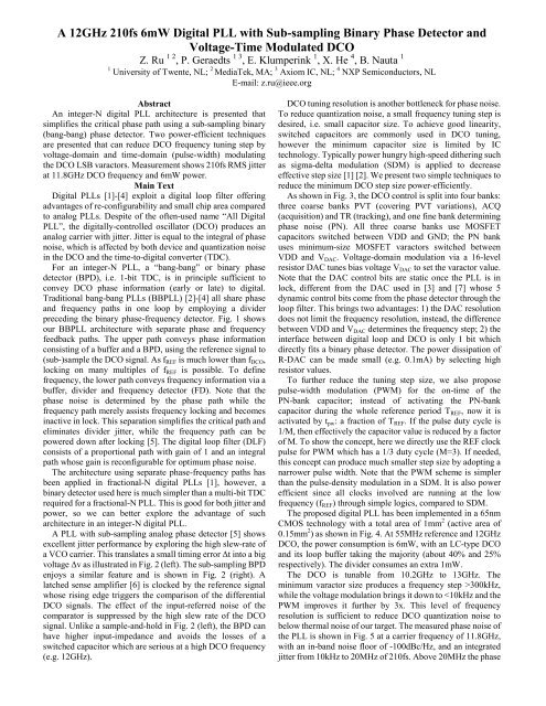
A <strong>12GHz</strong> <strong>210fs</strong> <strong>6mW</strong> <strong>Digital</strong> <strong>PLL</strong> <strong>with</strong> <strong>Sub</strong>-<strong>sampling</strong> <strong>Binary</strong> <strong>Phase</strong> Detector and<br />
Voltage-Time Modulated DCO<br />
Z. Ru 1 2 , P. Geraedts 1 3 , E. Klumperink 1 , X. He 4 , B. Nauta 1<br />
1 University of Twente, NL; 2 MediaTek, MA; 3 Axiom IC, NL; 4 NXP Semiconductors, NL<br />
E-mail: z.ru@ieee.org<br />
Abstract<br />
An integer-N digital <strong>PLL</strong> architecture is presented that<br />
simplifies the critical phase path using a sub-<strong>sampling</strong> binary<br />
(bang-bang) phase detector. Two power-efficient techniques<br />
are presented that can reduce DCO frequency tuning step by<br />
voltage-domain and time-domain (pulse-width) modulating<br />
the DCO LSB varactors. Measurement shows <strong>210fs</strong> RMS jitter<br />
at 11.8GHz DCO frequency and <strong>6mW</strong> power.<br />
Main Text<br />
<strong>Digital</strong> <strong>PLL</strong>s [1]-[4] exploit a digital loop filter offering<br />
advantages of re-configurability and small chip area compared<br />
to analog <strong>PLL</strong>s. Despite of the often-used name “All <strong>Digital</strong><br />
<strong>PLL</strong>”, the digitally-controlled oscillator (DCO) produces an<br />
analog carrier <strong>with</strong> jitter. Jitter is equal to the integral of phase<br />
noise, which is affected by both device and quantization noise<br />
in the DCO and the time-to-digital converter (TDC).<br />
For an integer-N <strong>PLL</strong>, a “bang-bang” or binary phase<br />
detector (BPD), i.e. 1-bit TDC, is in principle sufficient to<br />
convey DCO phase information (early or late) to digital.<br />
Traditional bang-bang <strong>PLL</strong>s (BB<strong>PLL</strong>) [2]-[4] all share phase<br />
and frequency paths in one loop by employing a divider<br />
preceding the binary phase-frequency detector. Fig. 1 shows<br />
our BB<strong>PLL</strong> architecture <strong>with</strong> separate phase and frequency<br />
feedback paths. The upper path conveys phase information<br />
consisting of a buffer and a BPD, using the reference signal to<br />
(sub-)sample the DCO signal. As f REF is much lower than f DCO ,<br />
locking on many multiples of f REF is possible. To define<br />
frequency, the lower path conveys frequency information via a<br />
buffer, divider and frequency detector (FD). Note that the<br />
phase noise is determined by the phase path while the<br />
frequency path merely assists frequency locking and becomes<br />
inactive in lock. This separation simplifies the critical path and<br />
eliminates divider jitter, while the frequency path can be<br />
powered down after locking [5]. The digital loop filter (DLF)<br />
consists of a proportional path <strong>with</strong> gain of 1 and an integral<br />
path whose gain is reconfigurable for optimum phase noise.<br />
The architecture using separate phase-frequency paths has<br />
been applied in fractional-N digital <strong>PLL</strong>s [1], however, a<br />
binary detector used here is much simpler than a multi-bit TDC<br />
required for a fractional-N <strong>PLL</strong>. This is good for both jitter and<br />
power, so we can better explore the advantage of such<br />
architecture in an integer-N digital <strong>PLL</strong>.<br />
A <strong>PLL</strong> <strong>with</strong> sub-<strong>sampling</strong> analog phase detector [5] shows<br />
excellent jitter performance by exploring the high slew-rate of<br />
a VCO carrier. This translates a small timing error Δt into a big<br />
voltage Δv as illustrated in Fig. 2 (left). The sub-<strong>sampling</strong> BPD<br />
enjoys a similar feature and is shown in Fig. 2 (right). A<br />
latched sense amplifier [6] is clocked by the reference signal<br />
whose rising edge triggers the comparison of the differential<br />
DCO signals. The effect of the input-referred noise of the<br />
comparator is suppressed by the high slew rate of the DCO<br />
signal. Unlike a sample-and-hold in Fig. 2 (left), the BPD can<br />
have higher input-impedance and avoids the losses of a<br />
switched capacitor which are serious at a high DCO frequency<br />
(e.g. <strong>12GHz</strong>).<br />
DCO tuning resolution is another bottleneck for phase noise.<br />
To reduce quantization noise, a small frequency tuning step is<br />
desired, i.e. small capacitor size. To achieve good linearity,<br />
switched capacitors are commonly used in DCO tuning,<br />
however the minimum capacitor size is limited by IC<br />
technology. Typically power hungry high-speed dithering such<br />
as sigma-delta modulation (SDM) is applied to decrease<br />
effective step size [1] [2]. We present two simple techniques to<br />
reduce the minimum DCO step size power-efficiently.<br />
As shown in Fig. 3, the DCO control is split into four banks:<br />
three coarse banks PVT (covering PVT variations), ACQ<br />
(acquisition) and TR (tracking), and one fine bank determining<br />
phase noise (PN). All three coarse banks use MOSFET<br />
capacitors switched between VDD and GND; the PN bank<br />
uses minimum-size MOSFET varactors switched between<br />
VDD and V DAC . Voltage-domain modulation via a 16-level<br />
resistor DAC tunes bias voltage V DAC to set the varactor value.<br />
Note that the DAC control bits are static once the <strong>PLL</strong> is in<br />
lock, different from the DAC used in [3] and [7] whose 5<br />
dynamic control bits come from the phase detector through the<br />
loop filter. This brings two advantages: 1) the DAC resolution<br />
does not limit the frequency resolution, instead, the difference<br />
between VDD and V DAC determines the frequency step; 2) the<br />
interface between digital loop and DCO is only 1 bit which<br />
directly fits a binary phase detector. The power dissipation of<br />
R-DAC can be made small (e.g. 0.1mA) by selecting high<br />
resistor values.<br />
To further reduce the tuning step size, we also propose<br />
pulse-width modulation (PWM) for the on-time of the<br />
PN-bank capacitor; instead of activating the PN-bank<br />
capacitor during the whole reference period T REF , now it is<br />
activated by t pw : a fraction of T REF . If the pulse duty cycle is<br />
1/M, then effectively the capacitor value is reduced by a factor<br />
of M. To show the concept, here we directly use the REF clock<br />
pulse for PWM which has a 1/3 duty cycle (M=3). If needed,<br />
this concept can produce much smaller step size by adopting a<br />
narrower pulse width. Note that the PWM scheme is simpler<br />
than the pulse-density modulation in a SDM. It is also power<br />
efficient since all clocks involved are running at the low<br />
frequency (f REF ) through simple logics, compared to SDM.<br />
The proposed digital <strong>PLL</strong> has been implemented in a 65nm<br />
CMOS technology <strong>with</strong> a total area of 1mm 2 (active area of<br />
0.15mm 2 ) as shown in Fig. 4. At 55MHz reference and <strong>12GHz</strong><br />
DCO, the power consumption is <strong>6mW</strong>, <strong>with</strong> an LC-type DCO<br />
and its loop buffer taking the majority (about 40% and 25%<br />
respectively). The divider consumes an extra 1mW.<br />
The DCO is tunable from 10.2GHz to 13GHz. The<br />
minimum varactor size produces a frequency step >300kHz,<br />
while the voltage modulation brings it down to
noise floor is due to DCO measurement buffer.<br />
Table 1 compares this work <strong>with</strong> other recently published<br />
bang-bang <strong>PLL</strong>s at ISSCC [2]-[4]. To a directly comparable<br />
11GHz <strong>PLL</strong> [2], this work achieves 2x better jitter at 1/5 power<br />
dissipation, thanks to the proposed techniques. Note that the<br />
200fs mentioned in the title of [2] does not count in-band phase<br />
noise due to a specific wireline application. For a figure of<br />
merit considering jitter and total power (FoM jitter ) [8], this<br />
work is at least 5dB better. Considering in-band phase noise<br />
and loop power (FoM IBPN ) [8] to compare <strong>PLL</strong>s using different<br />
DCO types, this work is at least 8dB better.<br />
Acknowledgements<br />
The authors thank Dutch government for funding the SPITS<br />
project and NXP for donating the chip fabrication.<br />
References<br />
[1] R. B. Staszewsk et. al., “All-<strong>Digital</strong> <strong>PLL</strong> and Transmitter for<br />
Mobile Phones”, JSSC 2005 December<br />
[2] A. Rylyakov et. al., “Bang-Bang <strong>Digital</strong> <strong>PLL</strong>s at 11 and 20GHz<br />
<strong>with</strong> sub-200fs Integrated Jitter for High-Speed Serial<br />
Communication Applications”, ISSCC 2009<br />
[3] D. Tasca et. al., “A 2.9-to-4.0GHz Fractional-N <strong>Digital</strong> <strong>PLL</strong> <strong>with</strong><br />
Bang-Bang <strong>Phase</strong> Detector and 560fsrms Integrated Jitter at 4.5mW<br />
Power”, ISSCC 2011<br />
[4] J. Hong et. al., “A 0.004mm2 250μW TDC <strong>with</strong> Time-Difference<br />
Accumulator and a 0.012mm2 2.5mW Bang-Bang <strong>Digital</strong> <strong>PLL</strong> Using<br />
PRNG for Low-Power SoC Applications”, ISSCC 2012<br />
[5] X. Gao et. al., “A Low Noise <strong>Sub</strong>-Sampling <strong>PLL</strong> in Which<br />
Divider Noise Is Eliminated and PD-CP Noise Is not multiplied by<br />
N2”, JSSC 2009 December<br />
[6] D. Schinkel et. al., “A Double-Tail Latch-Type Voltage Sense<br />
Amplifier <strong>with</strong> 18ps Setup+Hold Time”, ISSCC 2007<br />
[7] Fanori, et. al., “Capacitive Degeneration in LC-Tank Oscillator for<br />
DCO Fine-Frequency Tuning”, JSSC 2010 December<br />
[8] X. Gao et. al., "Jitter Analysis and a Benchmarking<br />
Figure-of-Merit for <strong>Phase</strong>-Locked Loops," TCAS-II, Feb. 2009<br />
REF<br />
BPD<br />
T REF<br />
Voltage-domain<br />
modulation by V DAC<br />
DLF<br />
t pw<br />
SEL<br />
PWM<br />
PVT<br />
ACQ<br />
TR<br />
PN<br />
VDAC<br />
DCO<br />
R-DAC<br />
DAC V DD-V V DD-V DAC<br />
V max<br />
V DD<br />
V max<br />
x =<br />
t pw<br />
t pw<br />
T REF<br />
T REF<br />
Time-domain<br />
modulation by t pw<br />
Combined voltage- and<br />
time-domain modulation<br />
Fig. 3. Reducing DCO minimum step size by voltage-domain<br />
modulation (V DAC ) and time-domain pulse-width modulation (PWM)<br />
1mm<br />
REF BUF<br />
DCO<br />
1mm<br />
DLF<br />
PD/BUF<br />
/FD/DIV<br />
Fig. 4. Micrograph of the 65nm CMOS chip (active area 0.15mm 2 )<br />
Fig. 1. <strong>Sub</strong>-<strong>sampling</strong> BB<strong>PLL</strong> architecture minimizing components on<br />
the critical phase path by separating the frequency path<br />
Fig. 2. <strong>Sub</strong>-<strong>sampling</strong> analog phase detector (left) and <strong>Sub</strong>-<strong>sampling</strong><br />
binary phase detector (right)<br />
Fig. 5. Measured phase noise at 11.8GHz carrier frequency<br />
This Work [2]<br />
ISSCC09<br />
[3]<br />
ISSCC11<br />
[4]<br />
ISSCC12<br />
DCO type LC LC LC Ring<br />
Carrier<br />
Frequency (f c )<br />
11.8GHz 11GHz 3.3GHz 1.5GHz<br />
In-Band <strong>Phase</strong><br />
Noise (IBPN)<br />
-100dBc/Hz -97dBc/Hz -102dBc/Hz -89dBc/Hz<br />
RMS Jitter (σ t )<br />
[10k to 20M]<br />
<strong>210fs</strong> 400fs 400fs 19ps<br />
Power<br />
DCO 2.5mW<br />
31mW<br />
1.7mW<br />
2.5mW<br />
Loop 3.5mW 2.8mW<br />
FoM jitter -246dB -233dB -241dB -210dB<br />
FoM<br />
1 IBPN -296dBc/Hz -286dBc/Hz -288dBc/Hz -272dBc/Hz<br />
CMOS Tech. 65nm 65nm 65nm 32nm<br />
1<br />
FoM for in-band phase noise: half of total power is assumed as loop power if<br />
no separate data reported.<br />
2<br />
2<br />
⎡⎛σ<br />
t ⎞ P ⎤<br />
⎡⎛1Hz<br />
⎞ ⎛ P<br />
tot<br />
loop ⎞⎤<br />
FoM<br />
jitter<br />
= 10log ⎢⎜<br />
⎟ ⋅ ⎥ FoM<br />
IBPN<br />
= IBPN + 10log ⎢⎜ ⎟ ⋅ ⎥<br />
⎢⎣<br />
⎝1s<br />
⎠ 1mW<br />
⎥<br />
f<br />
⎜<br />
1<br />
⎦<br />
c<br />
mW<br />
⎟<br />
⎢⎣<br />
⎝ ⎠ ⎝ ⎠⎥⎦<br />
Table 1. Comparison <strong>with</strong> other Bang-Bang <strong>PLL</strong>s