a study of wind-resistant safety design of wind turbines tower system
a study of wind-resistant safety design of wind turbines tower system
a study of wind-resistant safety design of wind turbines tower system

You also want an ePaper? Increase the reach of your titles
YUMPU automatically turns print PDFs into web optimized ePapers that Google loves.
The Seventh Asia-Pacific Conference on<br />
Wind Engineering, November 8-12, 2009,<br />
Taipei, Taiwan<br />
A STUDY OF WIND-RESISTANT SAFETY DESIGN OF WIND<br />
TURBINES TOWER SYSTEM<br />
Ching-Wen Chien 1 , Jing-Jong Jang 2<br />
1 Ph.D. Candidate, Department <strong>of</strong> Harbor and River Engineering, National Taiwan Ocean<br />
University/ E&C Engineering Corporation Keelung, Taiwan, Taiwan,<br />
d93520010@ntou.edu.tw<br />
2 Pr<strong>of</strong>essor, Department <strong>of</strong> Harbor and River Engineering, National Taiwan Ocean<br />
University Keelung, Taiwan, Taiwan, jangjj@ntou.edu.tw<br />
ABSTRACT<br />
During the last decade, many <strong>wind</strong> turbine <strong>tower</strong>s damage were caused by typhoons strike repeatedly. As the<br />
cost impact <strong>of</strong> buckling failure, this <strong>study</strong> starts to investigate the characteristics <strong>of</strong> <strong>wind</strong> turbulence and buckling<br />
resistance procedure is presented. The theories <strong>of</strong> the dynamic <strong>wind</strong> loading in along-<strong>wind</strong> and across-<strong>wind</strong><br />
with/without the torsional force are applied to analysis the total <strong>wind</strong> force. Furthermore, the finite element<br />
analysis is used to obtain the across-<strong>wind</strong> force <strong>of</strong> the response. Some basic features <strong>of</strong> the analysis and the<br />
<strong>design</strong> <strong>of</strong> the prototype <strong>of</strong> a steel 660 KW <strong>wind</strong> turbine <strong>tower</strong> in Taiwan are presented. These results <strong>of</strong> this<br />
research highlight the following: First, the 660 KW <strong>wind</strong> <strong>turbines</strong> <strong>tower</strong> should be <strong>design</strong>ed with natural period<br />
less than one second, and the gust effect factor, G, equal to 2.38. Second, at low mean <strong>wind</strong> velocities, due to the<br />
vortex shedding resonance with the fundamental mode <strong>of</strong> vibration, the across-<strong>wind</strong> response is higher than the<br />
along-<strong>wind</strong> response. Third, the turbulence intensity is observed to 25~44% in Typhoon Jangmi, and the along<strong>wind</strong><br />
response exceeds the total <strong>wind</strong> response. Fourth, the total <strong>wind</strong> force without considering torsional force<br />
will be underestimated 4.2%, therefore when the maximum deflection is closed to 1 %, the torsional force should<br />
not be ignored for the <strong>safety</strong> <strong>design</strong>.<br />
KEYWORDS: TORSIONAL WIND FORCE, WIND TURBINE TOWER, TOTAL WIND FORCE,<br />
TURBULENCE INTENSITY<br />
Introduction<br />
There are many different configurations <strong>of</strong> <strong>wind</strong> turbine generator <strong>system</strong> (WTGS) have<br />
been built in large amounts around the world. As the tubular <strong>tower</strong> occupies area smaller than<br />
the lattice steel <strong>tower</strong>, then the distance <strong>of</strong> the blade between the shaft is increased to reduce<br />
the aerodynamic effect (Chien and Jang, 2008a). Moreover, the tubular <strong>tower</strong>s are <strong>design</strong>ed as<br />
truncated cones with their diameter increasing towards the base in order to increase their<br />
strength and at the same time to save material (Stathopoulos and Baniotopoulos 2007).<br />
Consequently, the tubular <strong>tower</strong> has a large ratio <strong>of</strong> height to least horizontal dimension that<br />
makes it a particularly more slender and <strong>wind</strong>-sensitive than any other structures. On the one<br />
hand, from structural characteristics <strong>of</strong> the tubular <strong>tower</strong>, it is a statically-determinate<br />
structure, due to lack <strong>of</strong> the cumulated experience for the <strong>design</strong> in a proper way with respect<br />
to serviceability, strength and <strong>safety</strong> criteria. Therefore, such structures are easier failure than<br />
common structures. As in these areas with typhoon application <strong>of</strong> IEC-61400-1 codes or<br />
National standard <strong>wind</strong> codes and the fact that information on external conditions is limited<br />
may result in either too high cost or too high risk (Clausen and Pagalilawan, 2006). In 2003,
The Seventh Asia-Pacific Conference on Wind Engineering, November 8-12, 2009, Taipei, Taiwan<br />
the supporting <strong>of</strong> self-standing <strong>system</strong> were collapsed or partially damaged by Typhoon<br />
Maemi in Okinawa, Japan. The authors have investigated some failures from geometric<br />
properties <strong>of</strong> <strong>wind</strong> turbine <strong>tower</strong> due to typhoon strike (Jang, and Chien, 2009), developed the<br />
procedure <strong>of</strong> Wind-Resistant Design (WRD) for the support structures subjected to <strong>wind</strong>induced<br />
excitation from vortex shedding and gust buffeting (Chien and Jang, 2008b).<br />
The <strong>study</strong> is aimed at analyzing the Typhoon Jammie speed from the Central Weather<br />
Bureau to compare the <strong>design</strong> basis <strong>of</strong> <strong>wind</strong> turbine <strong>tower</strong>s. The authors deal with the<br />
classical problems <strong>of</strong> the dynamic along<strong>wind</strong> response and the equivalent static forces,<br />
referred to as the gust factors, aimed at determining the maximum response for engineering<br />
application to <strong>wind</strong> turbine <strong>tower</strong>s <strong>design</strong>. The authors have also obtained the regression<br />
formulas <strong>of</strong> natural period with/without turbine based on the theory <strong>of</strong> Generalized<br />
Coordinate System Method and FEM analysis (Chien and Jang, 2005). As the natural period<br />
is a good verification in the discrimination <strong>of</strong> 1sec. <strong>of</strong> natural periods to rigidity and flexible<br />
structure or not for a <strong>wind</strong> turbine <strong>tower</strong> than the ratio <strong>of</strong> Height/Diameter method (Chien and<br />
Jang, 2008b). On the other hand, the structure is usually assumed to undergo aerodynamic<br />
actions partly distributed along the axis <strong>of</strong> the shaft and partly concentrated in the geometrical<br />
center <strong>of</strong> the masses, therefore torsion load is always ignored (Solaria, 1999). As a matter <strong>of</strong><br />
fact, due to the turbulence or typhoon strike, the torsion <strong>of</strong> the shaft in the across<strong>wind</strong> planes<br />
should not be ignored. However, it’s still not found the application <strong>of</strong> torsion theory at present,<br />
only there are torsion theories in Japan's code (AIJ 1996). In the ASCE7 code adopts the<br />
eccentricity e for rigid structures to consider the torsional loads (ASCE7 2005). As for more<br />
accurate prediction <strong>of</strong> damage due to typhoon strike, it is important to compare the along<strong>wind</strong><br />
force to total <strong>wind</strong> force with/without the torsional force. A benchmark model is based<br />
on the VESTA’s 660 Kw (VESTA, 1998) prototype with Finite Element analysis performed<br />
by applying appropriately linearly elastic laws for the analysis <strong>of</strong> across-<strong>wind</strong> response.<br />
Furthermore, the <strong>design</strong> <strong>of</strong> the steel <strong>tower</strong> for gravity and <strong>wind</strong> loadings is according to the<br />
relevant Taiwan code the results <strong>of</strong> the analyses to perform. The <strong>study</strong> includes three parts:<br />
(1); along-<strong>wind</strong> response analysis; (2); across-<strong>wind</strong> response with/without torsional force<br />
analysis; (3) develops the procedure <strong>of</strong> WRD for a <strong>wind</strong> turbine <strong>tower</strong>.<br />
Turbulence Intensity and Typhoon Speed<br />
The turbulence intensity, also <strong>of</strong>ten referred to as turbulence level, is defined as<br />
I<br />
u<br />
u ' ( t)<br />
= (1)<br />
U<br />
where<br />
u ' ( t ) is the root-mean-square <strong>of</strong> the turbulent velocity fluctuations and U is the mean<br />
velocity. If the turbulent energy, k, is known<br />
u ' ( t)<br />
can be computed as<br />
1 2<br />
= + + = (2)<br />
3 3<br />
' 2 2 2<br />
u ( t) ( u( x, t) u( y, t) u( z, t) ) k<br />
U can be computed from the three mean velocity components U t ( x ) , U t ( y ) and U t ( z ) as<br />
U U x U y U z<br />
2 2 2<br />
= t ( ) + t ( ) + t ( )<br />
(3)<br />
2
The Seventh Asia-Pacific Conference on Wind Engineering, November 8-12, 2009, Taipei, Taiwan<br />
Turbulence is the factor which describes short term <strong>wind</strong> variation/fluctuations. WTGS<br />
<strong>design</strong>ed according to the special <strong>safety</strong> class as defined in Table 1. As defined in the IEC<br />
61400-1 <strong>wind</strong> turbine <strong>design</strong>/<strong>safety</strong> standard, the largest <strong>wind</strong> speed to be considered is called<br />
“V e50 ” which is the maximum gust over a 50-year return period for a 3-second averaging time.<br />
A <strong>design</strong>ates the category for higher turbulence characteristics, B <strong>design</strong>ates the category for<br />
lower turbulence characteristics, I 15 is the characteristic value <strong>of</strong> the turbulence intensity at 15<br />
m/s, a is the slope parameter (IEC-61400-1, 1998). Generally, a WTGS is supposed to be<br />
<strong>design</strong>ed to stop rotation for their blades , for example, changing pitch <strong>of</strong> blades in order to<br />
reduce <strong>wind</strong> loads on a <strong>tower</strong> and blades in case <strong>of</strong> high <strong>wind</strong> more than 25 m/s. The<br />
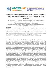
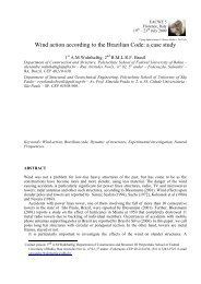
maximum allowable extreme <strong>wind</strong> speeds are listed in Table 2. Fig. 1(a) shows the path <strong>of</strong><br />
Typhoon Jangmi strike in Taiwan. Fig. 1(b) shows the maximum mean <strong>wind</strong> speed, the<br />
maximum instantaneous <strong>wind</strong> speed were observed 32m/s, 46.1m/s respectively, in the<br />
Wuchi station by the Central Weather Bureau. The turbulence intensity is equal to 44% by Eq.<br />
(1) as shown in Table 3. Typically the turbulence intensity is between 5% and 20 %.<br />
Therefore, due to this circumstance the <strong>tower</strong> is prone to buckling failure. On the other hand,<br />
the <strong>wind</strong> speed <strong>of</strong> average was 56m/s on the last ten minutes, the maximum instantaneous<br />
<strong>wind</strong> speed during the Typhoon Jangmi was investigated exceed 70 m/s by the Taiwan Power<br />
Company (TPC). Fig. 1(c) shows the broken <strong>tower</strong> <strong>of</strong> <strong>wind</strong> <strong>turbines</strong> by Typhoon Jangmi<br />
strike in Taiwan. Those exceeded IEC’s 50 year <strong>design</strong> <strong>wind</strong> speed U 50 for class I <strong>wind</strong><br />
turbine. Therefore it cannot be expected that <strong>design</strong>s made according to the IEC 61400-1 will<br />
ensure sufficient structural reliability <strong>of</strong> <strong>turbines</strong> in regions <strong>of</strong> the world, where typhoons<br />
occur.<br />
Buckling Resistance<br />
As the thickness is less than the radius <strong>of</strong> the shaft, the <strong>wind</strong> turbine <strong>tower</strong> should be<br />
considered as a thin wall structure. However, the formula <strong>of</strong> moment in inertia is derived<br />
3<br />
as I = π R t ; R is the average <strong>of</strong> radius; t is the thickness <strong>of</strong> the shaft. Usually, the<br />
manufactory and owner increased the radius R than the thickness <strong>of</strong> the shaft to obtain<br />
stronger the stiffness <strong>of</strong> the structure under the same total amount <strong>of</strong> steel weight. Due to this<br />
circumstance the <strong>tower</strong> is prone to local buckling. Concerning the fatigue limit state, the<br />
width to their thickness ratio should be satisfied the following <strong>of</strong> buckling resistance<br />
requirements. First, geometric <strong>design</strong> should be based on the diameter-thickness (D/t) ratio<br />
less than 125 to avoid the local buckling <strong>of</strong> <strong>wind</strong> turbine <strong>tower</strong>. Second, if the ratio <strong>of</strong> D/t is<br />
large than 125, moreover by Eq. (4) to control the buckling failure as follow (Schilling, 1965)<br />
50<br />
25<br />
0 5 10 15 20 25<br />
Max. Ave. Wind Speed<br />
40<br />
Max. Gust Wind Speed<br />
20<br />
Wind Speed(m/s)<br />
30<br />
15<br />
10<br />
20<br />
5<br />
10<br />
0 5 10 15 20 25<br />
Time (HR.)<br />
0<br />
Fig. 1: (a) Typhoon Jangmi (b) Wind Speeds in Wuchi Station (c) Broken WTGS<br />
3
The Seventh Asia-Pacific Conference on Wind Engineering, November 8-12, 2009, Taipei, Taiwan<br />
Table 1: Basic Parameters for WTGS Classes<br />
WTGS Class I II III IV<br />
U ref (m/s) 50 42.5 37.5 30<br />
U ave (m/s) 10 8.5 7.5 6<br />
A I 15 (-)<br />
0.18 0.18 0.18 0.18<br />
a (-) 2 2 2 2<br />
B I 15 (-)<br />
0.16 0.16 0.16 0.16<br />
a (-) 3 3 3 3<br />
Table 2: Wind Speed According to IEC/GL<br />
Max. 10 Max. 3 sec. Gust Stop <strong>wind</strong> speed<br />
min. mean mean max. acc.<br />
V47 – 660 kW 50 m/s 70 m/s 10 m/s 2 25 m/s<br />
Table 3: Wind Turbulence Intensity<br />
Stations Max. 10<br />
min. mean<br />
Max. 3 sec.<br />
mean<br />
Gust<br />
max. acc.<br />
turbulence<br />
intensity<br />
Wuchi station 32 m/s 46 m/s 14 m/s 2 44%<br />
TPC station 56 m/s 70 m/s 14 m/s 2 25%<br />
D<br />
< 0.1259⋅ E s , (4)<br />
t F y<br />
D is diameter <strong>of</strong> shaft, E s is modulus <strong>of</strong> elasticity, and F y is yield stress. Third, the ratio <strong>of</strong><br />
lateral deflection-height should be controlled less than 1% to avoid the buckling failure.<br />
Analysis <strong>of</strong> Along-Wind Load<br />
Davenport derives a factor, which the R.M.S. (Root Mean Square) component would be<br />
exceeded with a probability <strong>of</strong> 50%. After further refinement Davenport recommended the<br />
following expression for peak factor<br />
0.577<br />
g = 2× ln(3600 n)<br />
+<br />
, (5)<br />
2×<br />
ln(3600 n)<br />
where n is the natural frequency. Thus, maximum instantaneous <strong>wind</strong> velocity is then<br />
Umax = U + g ⋅ σ ( U ) , (6)<br />
The along-<strong>wind</strong> response is usually obtained by the gust effect factor method. This approach<br />
is based on the maximum response that can be represented by the corresponding mean<br />
response multiply a gust effect factor. The F<br />
d<br />
total drag force at any point for a <strong>wind</strong> turbine<br />
<strong>tower</strong> is given by Eq. (7), and the mean displacement <strong>of</strong> mean along-<strong>wind</strong> velocity at the<br />
average height point is obtained by Eq. (8)<br />
1<br />
H 2<br />
Fd = ⋅Cd ⋅ ρa<br />
⋅ ∫ V( z ) ⋅ B( z ) ⋅φ( z )dz<br />
0<br />
2<br />
, (7)<br />
Fd<br />
X ave = ; K 1 =m 1 (2πn 1 ) 2 ,<br />
K<br />
(8)<br />
1<br />
4
The Seventh Asia-Pacific Conference on Wind Engineering, November 8-12, 2009, Taipei, Taiwan<br />
On the one hand, the total along-<strong>wind</strong> displacement<br />
X<br />
a(max)<br />
( H ) can be divided into two parts:<br />
First, the average displacement x (H ) is caused by average <strong>wind</strong> speed. Second, the turbulent<br />
displacement x<br />
a(max)<br />
( H )is caused by the turbulence <strong>wind</strong> speed. Hence, the total along-<strong>wind</strong><br />
displacement <strong>of</strong> a structure subjected to along-<strong>wind</strong> force is given by Eq. (9), the gust effect<br />
factor G(z) is refered to Eqs. (8), (9) to obtain the Eq. (10):<br />
where<br />
X ( H ) = x( H ) + [( g σ ) + ( g σ ) ] = x( H ) + x<br />
a(max)<br />
( H ), (9)<br />
2 2 1/<br />
2<br />
a(max) B Bx R Rx<br />
x a (max)<br />
g = 2× ln( 3600n ) +<br />
R<br />
G( z) = 1+ x( z)<br />
, (10)<br />
0.<br />
577<br />
2×<br />
ln( 3600n )<br />
is the resonant peak factor, gB<br />
≅ 3.5 . σ<br />
BX is<br />
the R.M.S. value <strong>of</strong> the non-resonant displacement; σ<br />
RX is the R.M.S. value <strong>of</strong> the resonant<br />
displacement.<br />
Analysis <strong>of</strong> Across-Aind Load and Torsional Wind Load<br />
Due to vortex shedding, when the mean <strong>design</strong> <strong>wind</strong> speed (U H ) is greater than the critical<br />
across-<strong>wind</strong> speed (U cr ) that always falls in the resonance area. U H (m/sec) can be calculated<br />
by local <strong>wind</strong> code. When the <strong>wind</strong> velocity is located in vortex resonance area, <strong>design</strong> the<br />
<strong>wind</strong> turbine <strong>tower</strong> should be considered in the across-<strong>wind</strong> loads. Vortex resonance area is<br />
between 0.50 and 1.30U H as defined here. Lock-in effect is subjected to the vortex shedding<br />
frequency and structure natural frequency nearly; within certain range <strong>of</strong> <strong>wind</strong> velocities.<br />
With the round cylinder as an example when there is turbulence, it’s S t =0.2 and the U cr value<br />
can be obtained by Eq. (11):<br />
5D<br />
Ucr<br />
= , (11)<br />
T<br />
T j is the natural period <strong>of</strong> structure (j=1, 2….n). However, vortex shedding although can<br />
"lock-in" and continue as the velocity increases or decreases slightly, if the velocity changes<br />
by more than 30%, the vortex shedding will stop, and across-<strong>wind</strong> load is no need to consider<br />
at outside this range. The across-<strong>wind</strong> force is obtained by Eq. (12) (Tsai, et al., 2006).<br />
2 Z<br />
Wrz = Ucr ⋅ ⋅Cr<br />
⋅ A , (12)<br />
h<br />
W rz is the across-<strong>wind</strong> force at height z; C r is the <strong>wind</strong> force <strong>of</strong> vortex resonance; A is the<br />
project area <strong>of</strong> the structure. The tip displacement <strong>of</strong> the <strong>wind</strong> turbine <strong>tower</strong> in across-<strong>wind</strong><br />
force is obtained by Eq. (13) (Wang, 1995)<br />
2<br />
Ucr<br />
⋅ D ⋅φ( Z)<br />
X<br />
c<br />
=<br />
, (13)<br />
2<br />
8000⋅ξ<br />
⋅m⋅ω<br />
where ξ is the damping ratio <strong>of</strong> structure (=0.02); φ ( Z ) is a function <strong>of</strong> viration mode, the<br />
critical <strong>wind</strong> speeds for torsional <strong>wind</strong> force is obtained by Eq. (14) (Tsai, et al., 2006) form<br />
the torsion theories in Japan's code (AIJ 1996).<br />
j<br />
' Z 1<br />
Tz<br />
1.8 ( )<br />
T Z T<br />
1<br />
TR<br />
M = ⋅ q h ⋅ C ⋅ A ⋅ B ⋅ g R<br />
H<br />
⋅ ⋅ + β<br />
, (14)<br />
5
The Seventh Asia-Pacific Conference on Wind Engineering, November 8-12, 2009, Taipei, Taiwan<br />
q( h ) is a velocity pressure, C is the parameter <strong>of</strong> torsional <strong>wind</strong> force,<br />
'<br />
T<br />
A<br />
Z<br />
is the projected area at<br />
R is the coefficient <strong>of</strong><br />
height Z, g<br />
T<br />
is the coefficient <strong>of</strong> peak factor <strong>of</strong> torsional <strong>wind</strong> force,<br />
TR<br />
resonance factor <strong>of</strong> torsional <strong>wind</strong> force, β is the damping ratio, B is the projected breadth.<br />
The total dynamic <strong>wind</strong> load effect could be calculated as follow:<br />
X = X + X , (15)<br />
2 2<br />
t(max)<br />
a max c<br />
X t is total dynamic <strong>wind</strong> load; X a(max) and X c are effect <strong>of</strong> along-<strong>wind</strong> load and across-<strong>wind</strong><br />
load, respectively.<br />
Case Study and Procedure <strong>of</strong> Wind Resistat Design<br />
A benchmark <strong>of</strong> steel tubular <strong>tower</strong> is based on a VEST’s V47-660kw to set up where is<br />
located in the Wu-chi as shown in Figs. 2(a)~(c). Design <strong>of</strong> <strong>tower</strong> is made by steel structure<br />
with the piling foundation. As simplification calculation, the stepped cylindrical section is<br />
transformed into a uniform thickness. Therefore, the analysis is adopted the parameters <strong>of</strong> 2/3<br />
height for the <strong>wind</strong> turbine <strong>tower</strong>, the diameter is equal to 3(2.45) m, the thickness <strong>of</strong> shaft is<br />
15 (10) mm; the height is about 50m. The procedure <strong>of</strong> WRD as follow: First Step, the<br />
natural period <strong>of</strong> the benchmark is control in first mode by eignvalue analysis as shown in<br />
Table 4. As the benchmark is a symmetrical structure, their vibration periods are close to each<br />
other, the first two fundamental modes <strong>of</strong> the model are dominated by lateral translations.<br />
Second Step, the <strong>design</strong> <strong>wind</strong> speed is used by the Typhoon Jangmi (U 10 (C) =56m/s), the gust<br />
factor, along-<strong>wind</strong> displacement (X a ) is calculated by Eqs. (8)~(10) as shown in Table 5.<br />
Third Step, the analysis <strong>of</strong> across-<strong>wind</strong> resonance calculated by Eq. (11), one shall consider<br />
the across-<strong>wind</strong> force in the resonance area as shown in Table 4, and the results <strong>of</strong> across<strong>wind</strong><br />
force with/without torsional force is calculated by Eqs. (12), (14) as shown in Table 6.<br />
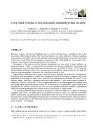
Fourth step, the across-<strong>wind</strong> force is applied into SAP2000 model to obtain the across-<strong>wind</strong><br />
displacement as shown in Fig. 3. As the maximum deflection is closed to 1 %, the ration is<br />
just satisfied to the buckling resistance requirements as shown in Table 5. Fifth step, Fig. 4<br />
compares the base moment <strong>of</strong> total <strong>wind</strong> force under U cr =15.6 (m/sec) with the only<br />
consideration <strong>of</strong> the along<strong>wind</strong> force under Typhoon Jangmi speed (U 10 =56m/s) or Taiwan<br />
<strong>wind</strong> code (U 10 =32.5m/s) for <strong>design</strong> the <strong>wind</strong> turbine <strong>tower</strong>.<br />
Figure 2: (a) Prototype <strong>of</strong> 660KW (b) Benchmark Model (c) Prototype (1 st mode shape)<br />
6
The Seventh Asia-Pacific Conference on Wind Engineering, November 8-12, 2009, Taipei, Taiwan<br />
Table 4 Analysis <strong>of</strong> Across-Wind Resonance (U h =U 10 (C)=56m/s)<br />
Numbers <strong>of</strong><br />
mode<br />
D<br />
(m)<br />
T j<br />
(sec)<br />
U cr<br />
(m/sec)<br />
U h<br />
(m/sec)<br />
Across-<strong>wind</strong><br />
resonance<br />
1 2.45, 3 1.039, 0.984 12, 15 71<br />
U h > U cr<br />
Lock-in<br />
2 2.45, 3 0.169, 0.223 73 , 67 71 U cr >20m/s<br />
Table 5 Analysis <strong>of</strong> Displacement and Gust Effect Factor (U 10 (C)=56m/s, D=3m, t=15mm)<br />
X ave X a(max) X c X t(max) Total<br />
Deflection<br />
G(Z)<br />
By equation Eq. (8) Eq. (9) Sap2000 Eq. (15) Eq. (15)/H Eq. (10)<br />
Unit (cm) (cm) (cm) (cm) %<br />
Benchmark 3.25 4.47 50.4 50.59 1 2.38<br />
60<br />
3000<br />
50.4<br />
D=3m , t=15mm<br />
Displacment(mm)<br />
40<br />
22.95<br />
36.38<br />
Base moment (t-m)<br />
2000<br />
Ma=Bending Moment(T-M)<br />
M a (U 10 =56 m/s)<br />
M a (U 10 =32.5m/s)<br />
M a (w/o Torsion force)<br />
M a (with Torsion force)<br />
20<br />
1000<br />
11.29<br />
3.11<br />
0<br />
0<br />
0<br />
0 10 20 30 40 50<br />
Height (m)<br />
Figure 3: Sap2000 Analysis <strong>of</strong><br />
Across-Wind Response (U cr =15m/s)<br />
0 10 20 30 40 50<br />
Height(m)<br />
Figure 4: Comparison <strong>of</strong> Basemoment<br />
Conclusions<br />
It’s recommended that the 660 KW <strong>wind</strong> <strong>turbines</strong> <strong>tower</strong> should be <strong>design</strong>ed with natural<br />
period less than one second, and the gust effect factor, G, equal to 2.38. Presently, the G value<br />
is greater than 1.77 for rigid structures according to the Taiwan building code 2006. As for<br />
results, Typhoon Jangmi speed (U 10 =56m/s) in along<strong>wind</strong> force is large than the total <strong>wind</strong><br />
force (U cr =15.6m/s, U 10 =11.37m/s in the along<strong>wind</strong> and cross<strong>wind</strong>) <strong>of</strong> WTGS. However, due<br />
to the large shaft flexibility, the torsional loading in the across<strong>wind</strong> response should not be<br />
ignored. It’s underestimated 4.2% in the total <strong>wind</strong> force without torsional <strong>wind</strong> force for<br />
<strong>safety</strong> <strong>design</strong>. When the maximum deflection is closed to 1 %, the torsional force should not<br />
be ignored for the stiffeners (stiffening rings, door tingers, ribs and frame) and the flanges to<br />
check against local buckling.<br />
7
The Seventh Asia-Pacific Conference on Wind Engineering, November 8-12, 2009, Taipei, Taiwan<br />
Table 6 Analysis <strong>of</strong> total <strong>wind</strong> force with/without torsional <strong>wind</strong> force for <strong>wind</strong>-power <strong>tower</strong><br />
(U cr =15m/s, U 10 =11m/s, D=3m, t=15mm)<br />
Height<br />
Dynamic<br />
along<strong>wind</strong><br />
force<br />
Across-<strong>wind</strong><br />
force w/o<br />
torsion force<br />
Torsional<br />
force<br />
Across-<strong>wind</strong><br />
force with<br />
torsional force<br />
Total <strong>wind</strong> force<br />
w/o torsional<br />
force<br />
Total <strong>wind</strong><br />
force with<br />
torsional force<br />
(m) (kg) (kg) (kg) (kg) (kg) (kg)<br />
50.00 325.97 14048.94 618.37 14667.31 14053 14671<br />
40.00 609.72 22478.30 989.40 23467.70 22487 23476<br />
30.00 559.31 16858.72 742.05 17600.77 16868 17610<br />
20.00 495.25 11239.15 494.70 11733.85 11250 11744<br />
10.00 382.15 5338.60 234.98 5573.58 5352 5587<br />
1.00 90.72 252.88 13.60 266.49 269 282<br />
total 2463.12 70216.58 3093.10 73309.69 70278.26 73368.67<br />
Acknowledgements<br />
The authors would like to thank the Taiwan Natural Science Council for finance support this<br />
research (NSC-98-2221-E-019-016).<br />
References<br />
AIJ, (1996), “AIJ Recommendations for Loads on Buildings”, Architectural Institute <strong>of</strong> Japan.<br />
ASCE-7, (2005), “Minimum Design Loads for Buildings and Other Structures”, American Society <strong>of</strong> Civil<br />
Engineers.<br />
Chien, C. W., and Jang, J. J. (2005), “Dynamic Analysis and Design <strong>of</strong> Tall Tower Structure”, Journal <strong>of</strong><br />
Building and Construction Technology, Vol.2, No.1, pp.25-35.<br />
Chien, C. W., and Jang, J. J. (2008), “A Study <strong>of</strong> Dynamic Analysis and Wind-<strong>resistant</strong> Safety Design <strong>of</strong> Wind<br />
Turbines”, Proc 3rd Taiwan Wind Energy Symp, TwnWEA, Taipei, pp 225-231.<br />
Chien, C. W., and Jang, J. J. (2008), “Case Study <strong>of</strong> Wind-Resistant Design and Analysis <strong>of</strong> High Mast Structures<br />
Based on Different Wind Codes”, Journal <strong>of</strong> Marine Science and Technology, Vol. 16, No. 4, pp. 273-285.<br />
Clausen Niels-Erik, and Pagalilawan E. M. (2006), “Design <strong>of</strong> Wind Turbines in an Area with Tropical<br />
Cyclones”, European Wind Energy Conference, Athens.<br />
IEC 61400-1 Ed.3, (2005), “International Electro-technical Commission”, Wind <strong>turbines</strong>-Part 1: Design<br />
requirement.<br />
Jang, J. J., and Chien, C. W. (2009), “A Study <strong>of</strong> Geometric Properties and Shape Factors for Design <strong>of</strong> Wind<br />
Turbine Tower”, 19th Int Offshore and Polar Eng Conf, Osaka, Japan, ISOPE, pp370-377.<br />
Schilling, C. G. (1965), “Buckling Strength <strong>of</strong> Circular Tubes”, Journal <strong>of</strong> the Structural Division 19, no. ST5.<br />
New York, American Society <strong>of</strong> Civil Engineers, 325-348.<br />
Solaria, G. (1999), “Gust Buffeting and Aeroelastic Behavior <strong>of</strong> Poles and Monotubular Tower”, Journal <strong>of</strong> the<br />
Fluids and Structures No.13, pp.877-905.<br />
Stathopoulos T. and Baniotopoulos C. C. (2007), “Wind Effect on Buildings and Design <strong>of</strong> Wind-Sensitive<br />
Structures”, CISM Courses and Lectures, SpringerWien NewYork.<br />
Tsai, I. C., Cherng, R. H., and Hsiang, W. B., (2006), “Establishment <strong>of</strong> Building Wind loading Code and the<br />
associated Commentary, Building research institute <strong>of</strong> Ministry <strong>of</strong> Internal Affairs.<br />
VESTAS Specification, (1998), “Wind System A/S Standard Foundation for Vestas V47-660/220 & V47-<br />
660/43.7M Tower”, VESTAS company.<br />
Wang, Z. M. (1995), “Tower structure <strong>design</strong> manual”, China Construction Industry Press.<br />
8