On the structural response of steel telecommunication lattice masts ...
On the structural response of steel telecommunication lattice masts ...
On the structural response of steel telecommunication lattice masts ...

You also want an ePaper? Increase the reach of your titles
YUMPU automatically turns print PDFs into web optimized ePapers that Google loves.
EACWE 5<br />
Florence, Italy<br />
19 th – 23 rd July 2009<br />
Flying Sphere image © Museo Ideale L. Da Vinci<br />
<strong>On</strong> <strong>the</strong> <strong>structural</strong> <strong>response</strong> <strong>of</strong> <strong>steel</strong> <strong>telecommunication</strong> <strong>lattice</strong> <strong>masts</strong><br />
for wind loading and combined effects<br />
Efthymiou E., Gerasimidis S. & Baniotopoulos C.C.<br />
Institute <strong>of</strong> Metal Structures, Department <strong>of</strong> Civil Engineering, Faculty <strong>of</strong> Engineering,<br />
Aristotle University <strong>of</strong> Thessaloniki GR- 54124, Thessaloniki, Greece<br />
vefth@civil.auth.gr, sgerasim@civil.auth.gr, ccb@civil.auth.gr<br />
Keywords: Steel <strong>lattice</strong> <strong>masts</strong>, wind loadings, <strong>structural</strong> codes, combined effects<br />
ABSTRACT<br />
In <strong>the</strong> last years, a lot <strong>of</strong> new issues have been arisen regarding <strong>the</strong> <strong>structural</strong> behaviour <strong>of</strong> <strong>steel</strong> <strong>lattice</strong><br />
<strong>masts</strong> which are used ei<strong>the</strong>r for <strong>telecommunication</strong> needs or as systems to transfer energy. As<br />
environmental effects are becoming more severe and <strong>the</strong> earthquake phenomenon is taken into<br />
account in a more detailed way according to <strong>the</strong> modern codes for earthquake resistance structures,<br />
<strong>the</strong> thorough investigation <strong>of</strong> <strong>the</strong> performance <strong>of</strong> <strong>the</strong>se structures becomes imperative. In addition,<br />
since <strong>the</strong>se two industries become strategic and growing in today’s economy, <strong>the</strong>ir <strong>structural</strong> safety<br />
and stability is considered vital. In some cases <strong>the</strong> financial and social consequences caused by a<br />
possible collapse <strong>of</strong> this kind <strong>of</strong> structures are considered as damaging as those caused by <strong>the</strong> collapse<br />
<strong>of</strong> traditionally significant infrastructure, such as bridges.<br />
The present paper aims at investigating <strong>the</strong> <strong>structural</strong> <strong>response</strong> <strong>of</strong> <strong>the</strong>se special structures subjected to<br />
<strong>the</strong> influence <strong>of</strong> wind loading, as well as <strong>the</strong> combination <strong>of</strong> wind loading and ice. For <strong>the</strong> purpose <strong>of</strong><br />
<strong>the</strong> herein presented research activity, 6 types <strong>of</strong> <strong>steel</strong> <strong>masts</strong> have been analysed, namely 4 <strong>masts</strong><br />
located on <strong>the</strong> ground and 2 <strong>masts</strong> located on buildings. The study was carried out by means <strong>of</strong><br />
innovative s<strong>of</strong>tware in order to introduce <strong>the</strong> wind actions as thoroughly as possible and simulation<br />
models have been configured for <strong>the</strong> <strong>masts</strong> under investigation incorporating all special geographical<br />
Contact person: Evangelos Efthymiou, Dr. Civil Engineer, Institute <strong>of</strong> Metal Structures, Department <strong>of</strong> Civil<br />
Engineering, Aristotle University <strong>of</strong> Thessaloniki, University Campus, GR-54124, Thessaloniki, Greece.<br />
Tel: +302310994223, Fax: +302310995642. E-mail vefth@civil.auth.gr
parameters and <strong>structural</strong> arrangements. The influence <strong>of</strong> <strong>the</strong> wind action on <strong>the</strong> <strong>structural</strong> behaviour<br />
<strong>of</strong> <strong>the</strong> <strong>lattice</strong> <strong>masts</strong> is highlighted through <strong>the</strong> results, whereas deformation configuration for all <strong>the</strong><br />
<strong>masts</strong> have been developed. In <strong>the</strong> last part <strong>of</strong> <strong>the</strong> paper, conclusive remarks concerning <strong>the</strong> <strong>structural</strong><br />
performance behaviour <strong>of</strong> each <strong>of</strong> <strong>the</strong> six types <strong>of</strong> <strong>steel</strong> <strong>telecommunication</strong> <strong>masts</strong> under <strong>the</strong> influence<br />
<strong>of</strong> wind actions, as well as <strong>the</strong> combined environmental effects have been extracted.<br />
1. ON THE STEEL LATTICE TELECOMMUNICATION MASTS<br />
1.1 General<br />
Steel <strong>masts</strong> belong to <strong>the</strong> category <strong>of</strong> those special <strong>steel</strong> tower structures which are used in <strong>the</strong><br />
<strong>telecommunication</strong> field for telephone and data transmission, as well as in energy transmission<br />
infrastructure where <strong>the</strong>y usually carry cable guys. Steel <strong>masts</strong> are <strong>of</strong>ten flexible and light structures<br />
and <strong>the</strong>ir common, cost effective practice is using an open <strong>lattice</strong>, lightweight but adequately stiff<br />
system, since a <strong>lattice</strong> morphology requires only half as much material as a free-standing tubular one<br />
with similar stiffness. In addition, <strong>the</strong> <strong>lattice</strong> system enables <strong>the</strong> modularity <strong>of</strong> construction so that <strong>the</strong><br />
<strong>masts</strong> can be transported in relatively small modules making easier to cope with difficult terrain and<br />
thus requiring less labor demands.<br />
As in many cases, <strong>steel</strong> <strong>lattice</strong> <strong>telecommunication</strong> <strong>masts</strong> have to be <strong>of</strong>ten placed in spots <strong>of</strong> maximum<br />
visibility, <strong>the</strong> choice <strong>of</strong> hill or mountain peaks for <strong>the</strong>ir erection is obvious. They are self-supporting<br />
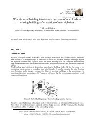
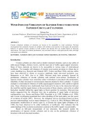
structures, <strong>the</strong>ir height varies from 5m to over 50m and <strong>the</strong>y can be found located ei<strong>the</strong>r on <strong>the</strong> ground<br />
or on <strong>the</strong> top <strong>of</strong> buildings when needed in <strong>the</strong> urban environment (Fig.1).<br />
i) ii)<br />
Figure 1: Steel <strong>lattice</strong> <strong>telecommunication</strong> <strong>masts</strong> located on i) ground ii) buildings<br />
According to <strong>the</strong> type <strong>of</strong> <strong>the</strong> mast and <strong>the</strong> <strong>telecommunication</strong> needs, <strong>the</strong>y carry dish reflectors or<br />
aerials-antennas at several heights <strong>of</strong> <strong>the</strong> structure, whereas in every tower <strong>the</strong>re are platforms at<br />
different levels <strong>of</strong> <strong>the</strong> mast according to <strong>the</strong> type <strong>of</strong> <strong>the</strong> mast, in order to enable inspections and<br />
maintenance operations. Inside <strong>the</strong> structure a ladder is constructed to provide climbing access, while<br />
special systems are configured in order to stabilize <strong>the</strong> feeders which connect <strong>the</strong> reflectors and<br />
antennas with <strong>the</strong> <strong>telecommunication</strong> network (Stathopoulos & Baniotopoulos 2007).
1.2 Morphology <strong>of</strong> <strong>the</strong> <strong>telecommunication</strong> <strong>masts</strong><br />
Steel <strong>lattice</strong> <strong>masts</strong> are tower structures <strong>of</strong> triangular, square or rectangular plan form which in <strong>the</strong><br />
<strong>structural</strong> design <strong>of</strong> <strong>the</strong>se structures is conventionally taken as <strong>the</strong> section <strong>of</strong> <strong>the</strong> mast. In view <strong>of</strong><br />
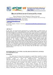
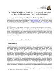
morphology, <strong>steel</strong> <strong>lattice</strong> <strong>masts</strong> have a vertical, a truncated cone system or a combination <strong>of</strong> <strong>the</strong> two<br />
systems where truncated cone base continues beyond <strong>of</strong> a specific height level as a prism, see Figure<br />
2. The legs (columns) <strong>of</strong> <strong>the</strong> mast are braced by means <strong>of</strong> main bracing <strong>of</strong> type X,Κ,V which transmit<br />
<strong>the</strong> shear forces to <strong>the</strong> foundation and at <strong>the</strong> same time provides stability against <strong>the</strong> horizontal<br />
seismic forces and <strong>the</strong> wind loading, while <strong>the</strong> secondary bracing reduces <strong>the</strong> member’s effective<br />
buckling length (Owens & Knowles 1994). There is also a plan bracing usually in a rhomboid<br />
formulation introduced mainly in cases where <strong>the</strong> length <strong>of</strong> <strong>the</strong> horizontal face members becomes<br />
large enough in order to provide transverse stability (Cook 2007) (Fig. 2).<br />
As far as <strong>the</strong> cross-sections <strong>of</strong> <strong>the</strong> members <strong>of</strong> <strong>the</strong> mast concern, <strong>the</strong>se are usually angle sections L,<br />
single or double for <strong>the</strong> legs, while for <strong>the</strong> horizontal face members, as well as <strong>the</strong> o<strong>the</strong>r elements <strong>of</strong><br />
<strong>the</strong> mast, <strong>the</strong> cross sections L and U are used. In cases where <strong>the</strong> stresses are low enough to allow<br />
relatively simple connections, tubular legs and bracings <strong>of</strong>fer appear to be an economic solution,<br />
since <strong>masts</strong> with tubular members may be less than half <strong>the</strong> weight <strong>of</strong> angle towers because <strong>of</strong> <strong>the</strong><br />
reduced wind load on circular sections. The disadvantage <strong>of</strong> this solution is that <strong>the</strong> extra cost <strong>of</strong> <strong>the</strong><br />
tube and <strong>the</strong> more complicated connection details <strong>of</strong>ten exceed <strong>the</strong> saving <strong>of</strong> <strong>steel</strong> weight and<br />
foundations.<br />
Figure 2: Types <strong>of</strong> <strong>steel</strong> <strong>lattice</strong> <strong>masts</strong> and <strong>the</strong> respective bracings forms<br />
2. ACTIONS ON STEEL LATTICE MASTS<br />
2.1 Permanent actions, imposed loadings and earthquake loading<br />
The basic loads that are considered in <strong>the</strong> design <strong>of</strong> a <strong>steel</strong> <strong>telecommunication</strong> <strong>lattice</strong> tower are <strong>the</strong><br />
dead loads <strong>of</strong> all <strong>the</strong> elements, <strong>the</strong> imposed live loads, <strong>the</strong> environmental loads and <strong>the</strong> earthquake<br />
action. Regarding <strong>the</strong> permanent actions on <strong>the</strong> <strong>steel</strong> mast, <strong>the</strong>se include <strong>the</strong> dead load <strong>of</strong> <strong>the</strong> structure
(<strong>the</strong> self-weight), <strong>the</strong> ladder, <strong>the</strong> several dish reflectors <strong>of</strong> different diameters that a mast carries and<br />
<strong>the</strong> working platform, located at specific heights <strong>of</strong> <strong>the</strong> structure, according to <strong>the</strong> type <strong>of</strong> <strong>the</strong> mast. As<br />
far as <strong>the</strong> imposed live loading is concerned, <strong>the</strong> calculation takes into account <strong>the</strong> variable loads <strong>of</strong><br />
<strong>the</strong> ladder and <strong>the</strong> working platform. Regarding <strong>the</strong> seismic loading, it can be particularly important<br />
in structures with high masses at <strong>the</strong> top.<br />
2.2 Environmental actions: Wind and ice loading<br />
As <strong>steel</strong> <strong>lattice</strong> <strong>masts</strong> are flexible structures, <strong>the</strong>y are primarily affected by <strong>the</strong> environmental loading.<br />
This way <strong>the</strong> effect <strong>of</strong> wind and ice consist <strong>the</strong> primary loading <strong>of</strong> <strong>the</strong>se structures, especially at high<br />
altitude (Simiu & Scanlan1996, Vayas et al. 2005). According to <strong>the</strong> current regulative norms, wind<br />
effects on <strong>steel</strong> <strong>masts</strong> can be considered ei<strong>the</strong>r on <strong>the</strong> basis <strong>of</strong> DIN 4131 or by implementing <strong>the</strong><br />
provisions <strong>of</strong> Eurocode1 in combination with Eurocode 3 (CEN 2005).<br />
As DIN 4131 dictates, in order to define <strong>the</strong> wind loading, it is necessary to calculate <strong>the</strong> wind<br />
pressure q at <strong>the</strong> specific level, <strong>the</strong> reference area A (<strong>the</strong> projected area <strong>of</strong> <strong>the</strong> structure normal to <strong>the</strong><br />
wind), <strong>the</strong> dynamic coefficient φ<br />
B<br />
and <strong>the</strong> aerodynamic loading coefficient c<br />
f<br />
(DIN 1991).Thus, <strong>the</strong><br />
wind loading on each reference area is calculated by means <strong>of</strong> <strong>the</strong> following formula:<br />
W= c f<br />
· φ<br />
B<br />
· q · A (1)<br />
Whenever <strong>the</strong> height <strong>of</strong> <strong>the</strong> tower does not exceed 50m, a constant value <strong>of</strong> <strong>the</strong> wind pressure q is<br />
taken into account that is equal to:<br />
⎛ h ⎞<br />
q = 0 . 75 ⋅ ⎜1<br />
+ ⎟⋅<br />
q o<br />
, (2)<br />
⎝ 100 ⎠<br />
where h is <strong>the</strong> height <strong>of</strong> <strong>the</strong> mast and q<br />
o<br />
is <strong>the</strong> basic wind pressure.<br />
The vibrations induced by <strong>the</strong> wind flow are taken into account by means <strong>of</strong> a dynamic coefficient φ<br />
B<br />
which is equal to<br />
φ φ ⋅ n , (3)<br />
Β<br />
= Β0<br />
where φ<br />
Β0<br />
is a function <strong>of</strong> <strong>the</strong> fundamental period <strong>of</strong> vibration and <strong>the</strong> logarithmic damping<br />
coefficient <strong>of</strong> <strong>the</strong> tower, while n is <strong>the</strong> size coefficient which in <strong>the</strong> case under investigation is equal<br />
to 1.<br />
The aerodynamic coefficient c f<br />
is a function <strong>of</strong> <strong>the</strong> wind (perpendicular or inclined action) and is<br />
defined as c<br />
f<br />
= c f 0<br />
⋅ψ<br />
. The values for c<br />
f 0<br />
and ψ are derived from <strong>the</strong> relevant nomograms from<br />
DIN 4131, as a function <strong>of</strong> <strong>the</strong> slenderness λ and <strong>the</strong> ratio <strong>of</strong> <strong>the</strong> covered area over <strong>the</strong> overall area <strong>of</strong><br />
<strong>the</strong> side face <strong>of</strong> <strong>the</strong> mast which is defined as <strong>the</strong> solidity ratioφ .<br />
The slenderness <strong>of</strong> <strong>the</strong> tower is given by means <strong>of</strong> <strong>the</strong> relations:<br />
λ = 0.7h / b , for h > 50m (4)<br />
λ = h / b , for h < 150m , (5)<br />
whereas h is <strong>the</strong> height <strong>of</strong> <strong>the</strong> tower above ground and b is <strong>the</strong> width <strong>of</strong> <strong>the</strong> tower at h/2 (b is measured<br />
perpendicularly to <strong>the</strong> wind direction). For intermediate h values, linear interpolation may be used.<br />
Regarding <strong>the</strong> Eurocode provisions, <strong>the</strong> mast is divided into a series <strong>of</strong> sections, where a section<br />
comprises several identical or nearly identical panels. When determining <strong>the</strong> projected area <strong>of</strong> <strong>the</strong><br />
structure, <strong>the</strong> projections <strong>of</strong> bracing members in faces parallel to <strong>the</strong> wind direction, as well in plan<br />
and hip bracing are omitted. The structure is divided into a sufficient number <strong>of</strong> sections to enable <strong>the</strong><br />
wind loading to be adequately modeled for <strong>the</strong> global <strong>structural</strong> analysis.<br />
According to Eurocode 1, <strong>the</strong> wind force is equal to:<br />
W<br />
∑<br />
F c c c q ( z ) A , (6)<br />
=<br />
s d f p e ref
where c<br />
f<br />
is <strong>the</strong> force coefficient for <strong>the</strong> structure or structure element, A<br />
ref<br />
is <strong>the</strong> reference area <strong>of</strong> <strong>the</strong><br />
structure or <strong>structural</strong> element, q p<br />
( z e<br />
) is <strong>the</strong> peak velocity pressure at reference height z e and c scd<br />
is<br />
<strong>the</strong> <strong>structural</strong> factor which takes into account <strong>the</strong> effect <strong>of</strong> wind actions from <strong>the</strong> non-simultaneous<br />
occurrence <strong>of</strong> peak wind pressures on <strong>the</strong> surface toge<strong>the</strong>r with <strong>the</strong> effect <strong>of</strong> <strong>the</strong> vibrations <strong>of</strong> <strong>the</strong><br />
structure due to <strong>the</strong> turbulence.<br />
The Eurocode framework provides analytical expressions for evaluating <strong>the</strong> wind drag <strong>of</strong> square or<br />
equilateral triangular <strong>lattice</strong> structures. The total wind force coefficient c<br />
f<br />
in <strong>the</strong> direction <strong>of</strong> <strong>the</strong> wind<br />
over a section <strong>of</strong> <strong>the</strong> structure should be taken as<br />
∑ c<br />
f<br />
= c<br />
f , S<br />
+ c<br />
f , A<br />
(7)<br />
Where c<br />
f , S<br />
is <strong>the</strong> wind force coefficient <strong>of</strong> <strong>the</strong> bare structure section, calculated by using <strong>the</strong> solidity<br />
ratioφ , appropriate to <strong>the</strong> bare structure, and c<br />
f , A<br />
is <strong>the</strong> wind force coefficient <strong>of</strong> <strong>the</strong> ancillaries. In<br />
cases, where <strong>the</strong> projected areas <strong>of</strong> ancillaries on each face are within 10% <strong>of</strong> each o<strong>the</strong>r, <strong>the</strong>y are<br />
considered as appropriate <strong>structural</strong> members.<br />
For a <strong>lattice</strong> mast <strong>of</strong> square or equilateral triangular plan form, having equal area on each face, <strong>the</strong><br />
total wind force coefficient c<br />
f<br />
<strong>of</strong> a section in <strong>the</strong> direction <strong>of</strong> <strong>the</strong> wind:<br />
c<br />
= K c , (8)<br />
f , S θ f , S ,0<br />
where c<br />
f ,S , 0<br />
is <strong>the</strong> overall normal drag (pressure) coefficient <strong>of</strong> a section j without end-effects and<br />
Kθ<br />
is <strong>the</strong> wind incidence factor which has different calculation expressions for square <strong>masts</strong> and for<br />
triangular structures<br />
Regarding <strong>the</strong> peak velocity pressure, it is depended from <strong>the</strong> mean wind velocity. This parameter is<br />
<strong>the</strong> 10-minute mean wind velocity at a specified height above ground appropriate for <strong>the</strong> exposure <strong>of</strong><br />
<strong>the</strong> site under consideration. The mean wind velocity v (z m<br />
) at a height z above <strong>the</strong> terrain depends<br />
on <strong>the</strong> terrain roughness and orography and on <strong>the</strong> basic wind velocity vb<br />
and is determined using <strong>the</strong><br />
following expression:<br />
v (z) m<br />
= c r<br />
(z)<br />
c o<br />
(z)<br />
v b<br />
, (9)<br />
where c r<br />
(z)<br />
is <strong>the</strong> roughness factor, c o<br />
(z)<br />
is <strong>the</strong> orography factor, which are usually taken as 1.0. It is<br />
noteworthy that <strong>the</strong> value <strong>of</strong> co<br />
is defined in <strong>the</strong> National Annex <strong>of</strong> each country. If <strong>the</strong> orography is<br />
accounted for in <strong>the</strong> basic wind velocity <strong>the</strong> recommended value is 1.0. In addition, design charts or<br />
tables for v (z m<br />
) may be given should be considered. The influence <strong>of</strong> neighboring structures on <strong>the</strong><br />
wind velocity should be considered (CEN 2004).<br />
The basic wind velocity v<br />
b<br />
is equal to:<br />
v<br />
b<br />
= c dir<br />
cseason<br />
v<br />
b,0<br />
(10)<br />
In this expression v<br />
b,0<br />
is <strong>the</strong> fundamental value <strong>of</strong> <strong>the</strong> basic wind velocity which is different for every<br />
country, cdir<br />
is <strong>the</strong> directional factor and c season<br />
is <strong>the</strong> season factor. The recommended value for <strong>the</strong><br />
both last factors is equal to 1.0, but <strong>the</strong>re are values for every country in <strong>the</strong> National Annex,<br />
The Eurocode regulative framework provides analytical expressions for <strong>the</strong> calculation <strong>of</strong> <strong>the</strong><br />
roughness factor at a height z, which accounts for <strong>the</strong> variability <strong>of</strong> <strong>the</strong> mean wind velocity at <strong>the</strong> site<br />
<strong>of</strong> <strong>the</strong> structure due to <strong>the</strong> height above ground level or <strong>the</strong> ground roughness <strong>of</strong> <strong>the</strong> terrain upwind <strong>of</strong><br />
<strong>the</strong> structure in <strong>the</strong> wind direction considered.<br />
According to <strong>the</strong> detailed procedure described in Eurocode 1, <strong>the</strong> <strong>structural</strong> factor<br />
c c<br />
s<br />
d<br />
c scd<br />
is equal to:<br />
2 2<br />
1+<br />
2k<br />
pIv<br />
( ze<br />
) B + R<br />
= , (11)<br />
1+<br />
7I<br />
( z )<br />
v<br />
e<br />
where ze<br />
is <strong>the</strong> reference height, k<br />
p<br />
is <strong>the</strong> peak factor defined as <strong>the</strong> ratio <strong>of</strong> <strong>the</strong> maximum value <strong>of</strong>
2<br />
<strong>the</strong> fluctuating part <strong>of</strong> <strong>the</strong> <strong>response</strong> to its standard deviation, I V<br />
is <strong>the</strong> turbulence intensity, B is <strong>the</strong><br />
background factor and is <strong>the</strong> resonance <strong>response</strong> factor, allowing for turbulence in resonance with <strong>the</strong><br />
vibration mode.<br />
2.3 Ice loading<br />
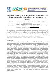
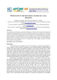
The effect <strong>of</strong> ice is introduced in <strong>the</strong> design <strong>of</strong> <strong>lattice</strong> <strong>masts</strong> by increasing <strong>the</strong> cross-section <strong>of</strong> all <strong>the</strong><br />
<strong>structural</strong> elements by 1cm to 10cm, depending on <strong>the</strong> exact altitude that <strong>the</strong> mast is erected, as well<br />
as increasing <strong>the</strong> section <strong>of</strong> <strong>the</strong> reflectors, see Figure 3 ((DIN 2002, CEN 2004). This way, <strong>the</strong><br />
distributed load is applied along all <strong>structural</strong> members, components <strong>of</strong> ladders, ancillaries etc.<br />
proportionally to <strong>the</strong> thickness <strong>of</strong> <strong>the</strong> element and <strong>the</strong> unit weight <strong>of</strong> <strong>the</strong> ice, 7kN/m 3 .<br />
A<br />
α<br />
t<br />
α<br />
α<br />
b<br />
α<br />
i) ii)<br />
Figure 3: i) Iced conditions on <strong>steel</strong> <strong>telecommunication</strong> <strong>lattice</strong> mast ii) Influence <strong>of</strong><br />
ice on angle cross-sections<br />
2.4 Combined effects<br />
In determining <strong>the</strong> wind force under iced conditions, <strong>the</strong> projected areas <strong>of</strong> <strong>structural</strong> elements and<br />
ancillaries should be increased to take due account <strong>the</strong> thickness <strong>of</strong> ice. In this case, <strong>the</strong> wind<br />
resistance <strong>of</strong> a structure and ancillaries under iced conditions for each element <strong>of</strong> <strong>the</strong> structure,<br />
ancillary parts and guys should be taken as coated on all sides by ice with a thickness <strong>of</strong> that given in<br />
Annex C. According to relevant codes, where <strong>the</strong> gap between components not iced is less than<br />
75mm, this should be assumed to be completely filled by ice under icing conditions, whereas <strong>the</strong><br />
force coefficients <strong>of</strong> individual members are obtained from <strong>the</strong> respective provisions.<br />
3. STUDY OF THE STEEL LATTICE MASTS: ANALYSIS AND RESULTS<br />
In <strong>the</strong> last years, <strong>the</strong> changes and additions in <strong>the</strong> normative framework <strong>of</strong> actions on <strong>the</strong> <strong>masts</strong>, <strong>the</strong><br />
installation new dish reflectors and antennas in combination with <strong>the</strong> new provisions <strong>of</strong> <strong>the</strong> codes for<br />
earthquake resistance structures, especially in countries like Greece where seismic risk is high,<br />
created <strong>the</strong> need for investigating <strong>the</strong> existing <strong>telecommunication</strong> network in new perspective<br />
(Dasiou et al. 2008, Vayas et al. 2005, Tsitlakidou et al. 2005). The <strong>steel</strong> <strong>lattice</strong> <strong>masts</strong> under
investigation cover a big part <strong>of</strong> <strong>the</strong> <strong>steel</strong> <strong>telecommunication</strong> mast industry <strong>of</strong> Greece, where a large<br />
number <strong>of</strong> <strong>the</strong>se tower structures which was built in <strong>the</strong> decades 1970s-1980s, are characterized by a<br />
variety <strong>of</strong> constructional arrangement (Hatzinikolis et al. 2008).<br />
The present paper deals with <strong>the</strong> study <strong>of</strong> <strong>the</strong> four most commonly used types <strong>of</strong> <strong>steel</strong> <strong>lattice</strong><br />
<strong>telecommunication</strong> towers located on ground as well as with two <strong>masts</strong> located on top on buildings,<br />
and focuses on <strong>the</strong>ir behaviour especially regarding <strong>the</strong> influence <strong>of</strong> <strong>the</strong> environmental actions and<br />
<strong>the</strong> combined effects on <strong>the</strong>ir <strong>structural</strong> capacity. Four characteristic examples <strong>of</strong> self-supporting <strong>steel</strong><br />
<strong>lattice</strong> <strong>telecommunication</strong> <strong>masts</strong> located on ground each one with base dimensions <strong>of</strong> 0.50m x 0.50m,<br />
1.40m x1.40m, 2.50m x 2.50m and 4.30m x 4.00m, are studied. The study also included two types <strong>of</strong><br />
<strong>masts</strong> located on <strong>the</strong> top <strong>of</strong> buildings in an urban environment with sections 3.00m x 4.80m and<br />
4.00m x 6.40m. Each mast has different cross sections, while <strong>the</strong> number and <strong>the</strong> size <strong>of</strong> <strong>the</strong><br />
dish-reflectors and aerials also differ. In Table I, <strong>the</strong> sections <strong>of</strong> <strong>the</strong> main members <strong>of</strong> <strong>the</strong> structures,<br />
namely <strong>the</strong> legs, <strong>the</strong> horizontal face members are shown with respect to <strong>the</strong> dimension <strong>of</strong> each mast.<br />
Dimension Legs Horizontal face members Main bracings<br />
0.50m x 0.50m L80x8 L70x7 L45x5<br />
1.40m x 1.40m L80x10 L60x6 L60x6<br />
2.50m x 2.50m L80x10 L70x7 L60x6<br />
4.30m x 4.00m L120x12, L110x10 L70x7 L60x6<br />
3.00m x 4.80m L100x10 L70x7, L80x8 L70x7<br />
4.00m x 6.40m L150x15, L110x10 L70x7 L70x7<br />
Table I: Cross-sections <strong>of</strong> <strong>the</strong> <strong>steel</strong> <strong>masts</strong> under investigation<br />
The mast with dimension 0.50mx0.50m has height equal to 6m, while <strong>the</strong> 1.40x1.40 mast is 8m tall.<br />
In <strong>the</strong> case <strong>of</strong> <strong>the</strong> 2.50m x 2.50m mast <strong>the</strong> height is h=12m, while <strong>the</strong> mast <strong>of</strong> 4.30x4.00 has height<br />
equal to h=18m. As far as <strong>the</strong> <strong>masts</strong> that are located on <strong>the</strong> top <strong>of</strong> buildings is concerned, <strong>the</strong>ir height<br />
is 12m for 3.00m x 4.80m mast and h=15m in <strong>the</strong> case <strong>of</strong> <strong>the</strong> mast with base dimension 4.00x6.40,<br />
whereas an additional parameter in <strong>the</strong> analysis is <strong>the</strong> height <strong>of</strong> <strong>the</strong> buildings, which is equal to 10m<br />
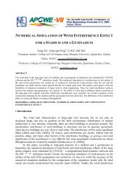
and 17.65m respectively. All special features <strong>of</strong> <strong>the</strong> material, <strong>the</strong> used bolts, as well as <strong>the</strong> geometrical<br />
parameters and local conditions were incorporated in <strong>the</strong> simulation models, see Figure 4.<br />
a) b) c) d) e) f)<br />
Figure 4: Simulation models <strong>of</strong> <strong>steel</strong> <strong>masts</strong> located on <strong>the</strong> ground (a,b,c,d) and<br />
located on buildings (e,f)
The basic loads considered in <strong>the</strong> study <strong>of</strong> <strong>the</strong> <strong>masts</strong> were <strong>the</strong> dead loads <strong>of</strong> all <strong>the</strong> elements, <strong>the</strong><br />
imposed live loads, <strong>the</strong> environmental loads and <strong>the</strong> earthquake action. Regarding <strong>the</strong> permanent<br />
actions on <strong>the</strong> <strong>steel</strong> mast, <strong>the</strong>se included <strong>the</strong> dead load <strong>of</strong> <strong>the</strong> structure (<strong>the</strong> cross-sections used), <strong>the</strong><br />
ladders, <strong>the</strong> antennas and <strong>the</strong> platforms. As far as <strong>the</strong> imposed live loading is concerned, <strong>the</strong><br />
calculation was carried out taking into account <strong>the</strong> variable loads <strong>of</strong> <strong>the</strong> staircase and <strong>the</strong> working<br />
deck.<br />
For <strong>the</strong> purposes <strong>of</strong> this research, <strong>the</strong> determination <strong>of</strong> <strong>the</strong> wind loads was carried out on <strong>the</strong> basis<br />
<strong>of</strong> DIN 4131, which provides <strong>the</strong> methodology for all <strong>the</strong> relevant calculations. It should be noted<br />
here that DIN 4131 being a complete and extensively tested group <strong>of</strong> rules gives very similar results<br />
to EC1, while it is generally compatible with <strong>the</strong> Eurocodes applied later in <strong>the</strong> analysis (Efthymiou<br />
& Baniotopoulos 2008).<br />
Regarding <strong>the</strong> effect <strong>of</strong> ice and for simplification purposes, it was taken into account by increasing<br />
<strong>the</strong> cross-section <strong>of</strong> all <strong>the</strong> <strong>structural</strong> elements by two times <strong>the</strong> thickness <strong>of</strong> <strong>the</strong> layer <strong>of</strong> <strong>the</strong> snow<br />
(0.06m). In <strong>the</strong> case <strong>of</strong> wind combined with <strong>the</strong> ice, <strong>the</strong> value <strong>of</strong> <strong>the</strong> wind pressure is calculated as<br />
75% <strong>of</strong> <strong>the</strong> initial value. As far as <strong>the</strong> seismic analysis <strong>of</strong> <strong>the</strong> structures is concerned, it was based on<br />
a Spectral Response Analysis, which was performed according to <strong>the</strong> Codes, taking into account <strong>the</strong><br />
special regional characteristics <strong>of</strong> <strong>the</strong> specific mast (EPPO 2000). Each mast exhibits a different<br />
design spectrum depending on <strong>the</strong> geographic location, meaning a different zone <strong>of</strong> earthquake<br />
hazard (zones I, II, III) and is equal to:<br />
n ⋅ A⋅<br />
g ⋅γ<br />
I<br />
⋅θ<br />
⋅ β<br />
Φ T =<br />
ο<br />
d<br />
( )<br />
, (12)<br />
q<br />
whereas γ 1 is <strong>the</strong> importance factor, θ is <strong>the</strong> foundation factor and n is <strong>the</strong> correctional damping factor.<br />
In <strong>the</strong> present study, a behavior factor <strong>of</strong> q=1 is considered for <strong>the</strong> reassurance <strong>of</strong> <strong>the</strong> desirable elastic<br />
<strong>response</strong> <strong>of</strong> <strong>the</strong> mast, for reasons <strong>of</strong> extra safety, while for simplification reasons a soil category Β is<br />
applied and all <strong>the</strong> temperature and aero elastic phenomena effects are disregarded. In <strong>the</strong> case <strong>of</strong> <strong>the</strong><br />
<strong>steel</strong> <strong>masts</strong> located on buildings, <strong>the</strong> wind velocity changes as <strong>the</strong> height is increasing by <strong>the</strong> height <strong>of</strong><br />
<strong>the</strong> building, whereas <strong>the</strong> introduction <strong>of</strong> <strong>the</strong> earthquake loading is changing according to <strong>the</strong> codified<br />
provisions.<br />
The basic load combinations for which <strong>the</strong> internal forces and moments were calculated are shown in<br />
Table II.<br />
A/A<br />
Load Combinations<br />
1 1.35G+1.5Q<br />
2 1.35G+1.5W 0<br />
3 1.35G+1.5W 0 +0.9Q<br />
4 1.35G+1.5W 0S +1.5S<br />
5 1.35G+1.5W 0S +1.5S+0.9Q<br />
6 1.35G+1.5S+0.9Q<br />
7 G+0.3S+0.3Q±E<br />
Table II: Basic loading combinations<br />
For each mast, <strong>the</strong> internal forces and moments were calculated and <strong>the</strong> members <strong>of</strong> every mast, i.e.<br />
<strong>the</strong> legs, <strong>the</strong> horizontal face members, <strong>the</strong> main, secondary and plan bracing were checked by means<br />
<strong>of</strong> <strong>the</strong> provisions <strong>of</strong> Eurocode 3 (CEN 2002).<br />
The results had shown that in all types <strong>of</strong> <strong>masts</strong>, <strong>the</strong> most severe action is <strong>the</strong> combination <strong>of</strong> wind<br />
with ice loading. In Figure 5 <strong>the</strong> exploitation ratios, namely <strong>the</strong> resistance ratio along with <strong>the</strong> wind<br />
actions for each type <strong>of</strong> mast are shown. The combined effect <strong>of</strong> wind and ice is <strong>the</strong> critical loading<br />
condition which in many cases it led to exceeding <strong>the</strong> strength <strong>of</strong> <strong>the</strong> <strong>steel</strong> mast members. Based on<br />
<strong>the</strong> analyses at hand, it is stated that wind action can be considered as <strong>the</strong> primary environmental<br />
action that has to be taken into consideration in <strong>the</strong> design <strong>of</strong> <strong>the</strong> <strong>steel</strong> <strong>lattice</strong> <strong>masts</strong>.
i) Mast on ground-0.50x0.50-h=6m ii) Mast on ground-1.40x1.40-h=8m<br />
iii) Mast on ground-2.50x2.50-h=12m<br />
iv) Mast on ground-4.30x4.00-h=18m<br />
v) Mast on building-3.00x4.80-h=12m vi) Mast on building-4.00x6.40-h=15m<br />
Figure 5: Types <strong>of</strong> <strong>masts</strong> and wind actions in relation to exploitation ratios<br />
In addition, as <strong>the</strong> height increases, <strong>the</strong> lower part <strong>of</strong> <strong>the</strong> legs exhibits inadequacy, while <strong>the</strong><br />
members used for <strong>the</strong> plan horizontal bracing and <strong>the</strong> platforms are subjected to significant bending<br />
stresses. In <strong>the</strong> case where <strong>the</strong> replacement <strong>of</strong> <strong>the</strong> members is not possible, <strong>the</strong>n streng<strong>the</strong>ning<br />
interventions are proposed such as construction <strong>of</strong> diaphragms aiming to restrain <strong>of</strong> <strong>the</strong> out-<strong>of</strong>-plane<br />
motion (reduction in <strong>the</strong> out-<strong>of</strong>-plane buckling length) or <strong>the</strong> addition <strong>of</strong> horizontal or diagonal<br />
members (in plan view).<br />
Regarding <strong>the</strong> seismic loads, although <strong>the</strong> isolated seismic case is not a critical one, <strong>the</strong> dynamic<br />
analysis shows that <strong>the</strong> seismic combination gives rise to high stresses that reach <strong>the</strong> capacity limits.<br />
In case <strong>of</strong> <strong>masts</strong> with small relative height, <strong>the</strong> performance <strong>of</strong> <strong>the</strong> structures is not affected. However,<br />
as <strong>the</strong> height increases, <strong>the</strong> seismic combinations cause more and more negative consequences,
especially in cases <strong>of</strong> <strong>the</strong> main bracings <strong>of</strong> <strong>the</strong> <strong>masts</strong> on <strong>the</strong> ground with sections 2.50x2.50,<br />
4.30x4.00 and <strong>the</strong> mast located on buildings.<br />
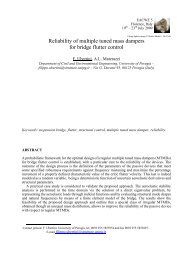
With respect to <strong>the</strong> deformations developing at <strong>the</strong> top <strong>of</strong> <strong>the</strong> <strong>steel</strong> <strong>lattice</strong> <strong>masts</strong>, in Figure 6 <strong>the</strong><br />
maximum values <strong>of</strong> <strong>the</strong> horizontal displacements are depicted. It is observed that <strong>the</strong> maximum<br />
displacements have been caused due to <strong>the</strong> combined effect <strong>of</strong> wind and ice and as <strong>the</strong> height <strong>of</strong> <strong>the</strong><br />
mast increases, <strong>the</strong> displacements increase.<br />
Horizontal displacement Ux(mm)<br />
30<br />
25<br />
20<br />
15<br />
10<br />
5<br />
0<br />
8.484<br />
h=6m<br />
0.50x0.50<br />
Ground<br />
10.954<br />
h=8m<br />
1.40x1.40<br />
Ground<br />
14.204<br />
h=12m<br />
2.50x2.50<br />
Ground<br />
21.474 20.456<br />
h=18m<br />
4.30x4.00<br />
Ground<br />
h=12m<br />
3.00x4.80<br />
Building<br />
25.25<br />
h=15m<br />
4.00x6.40<br />
Building<br />
Horizontal displacement Uy(mm)<br />
16<br />
14<br />
12<br />
10<br />
8<br />
6<br />
4<br />
2<br />
0<br />
1.994<br />
h=6m<br />
0.50x0.50<br />
Ground<br />
2.841<br />
h=8m<br />
1.40x1.40<br />
Ground<br />
5.285<br />
h=12m<br />
2.50x2.50<br />
Ground<br />
15.161<br />
h=18m<br />
4.30x4.00<br />
Ground<br />
11.569<br />
h=12m<br />
3.00x4.80<br />
Building<br />
15.178<br />
h=15m<br />
4.00x6.40<br />
Building<br />
Figure 6: Maximum horizontal displacement at <strong>the</strong> top <strong>of</strong> each mast<br />
Note that in <strong>the</strong> previous diagrams, ra<strong>the</strong>r strong variation in <strong>the</strong> respective displacements is observed<br />
due to <strong>the</strong> different distributions <strong>of</strong> aerials and reflectors.<br />
4. CONCLUSIVE REMARKS<br />
Nowadays, a well-established framework <strong>of</strong> recommendations and codes is available for <strong>the</strong><br />
design <strong>of</strong> <strong>steel</strong> <strong>lattice</strong> <strong>telecommunication</strong> <strong>masts</strong> structures, in order to assess <strong>the</strong> wind forces in detail<br />
so that <strong>the</strong> respective mast to be able to withstand <strong>the</strong> critical situations. This way, such structures can<br />
be analyzed and designed in an effective and safe way, whereas <strong>the</strong>ir peculiarities can be dealt in a<br />
correct way.<br />
The analysis showed that <strong>the</strong> predominant loads <strong>of</strong> <strong>steel</strong> <strong>lattice</strong> <strong>masts</strong> are <strong>the</strong> wind and <strong>the</strong> ice, as<br />
well as <strong>the</strong>ir combination. As slender structures, <strong>the</strong> <strong>masts</strong> are especially sensitive to <strong>the</strong> wind and<br />
<strong>the</strong>ir <strong>structural</strong> behaviour is strongly affected by <strong>the</strong> environmental actions. The wind pressure itself<br />
produces significant forces and results to high capacity ratios on <strong>the</strong> members, but combined with <strong>the</strong><br />
ice loading, it causes <strong>the</strong> maximum displacements and many members exceed <strong>the</strong>ir <strong>structural</strong><br />
capacity. Ice on a mast causes additional weight and this changes <strong>the</strong> dynamic behaviour as well as it<br />
can increase <strong>the</strong> wind drag <strong>of</strong> <strong>the</strong> <strong>lattice</strong> structure in a dramatic way.
ACKNOWLEDGEMENTS<br />
The authors would like to thank Ass. Pr<strong>of</strong>essor Dr. Civil Engineer E. Koltsakis for <strong>the</strong> development<br />
<strong>of</strong> <strong>the</strong> innovative analysis s<strong>of</strong>tware “Istos” that was used in <strong>the</strong> study <strong>of</strong> <strong>the</strong> <strong>masts</strong> for <strong>the</strong> evaluation<br />
<strong>of</strong> <strong>the</strong> wind in a very automatic and detailed manner. Parts <strong>of</strong> <strong>the</strong> herein described research work has<br />
been performed within <strong>the</strong> framework <strong>of</strong> <strong>the</strong> project “Assessment, Ranking and Reduction <strong>of</strong> <strong>the</strong><br />
Seismic Risk <strong>of</strong> <strong>the</strong> National Telecommunications Network”, supported by <strong>the</strong> Greek General<br />
Secretariat <strong>of</strong> Research and Technology and <strong>the</strong> National Telecommunication Organization <strong>of</strong><br />
Greece (OTE).<br />
REFERENCES<br />
Stathopoulos T., Baniotopoulos C. C. (2007). Wind effects on Buildings and design <strong>of</strong> wind-sensitive structures. CISM,<br />
SpringerWienNewYork, Udine.<br />
Owens G., Knowles P. (1994). Steel Designer’s Manual. The Steel Construction Institute, 5 th Edition, Blackwell Science.<br />
Cook N. (2007). Designers’ Guide to EN 1991-1-4 Eurocode 1: Actions on structures, general actions part 1.4. Wind<br />
action. Thomas Telford, London.<br />
Simiu E., Scanlan R. (1996). Wind effects on Structures. John Wiley & Sons, New York.<br />
Vayas Ι., Spiliopoulos A., Papageorgiou M. & Chatzinikolis I. (2005). “Vulnerability <strong>of</strong> Telecommunication towers”,<br />
Proc. <strong>of</strong> <strong>the</strong> 5 th National Conference on Metal Structures. Xanthi, Greece, Vol. II, pp. 230−237.<br />
CEN-European Committee for Standardisation. (2005). prEN 1993-3-1, Eurocode 3: Design <strong>of</strong> Steel Structures-Part 3.1:<br />
Towers and Masts , CEN, Brussels.<br />
DIN-Deutsches Institut für Normung. (1991). DIN 4131. Antennentragwerke aus Stahl, Deutsches Institut für Normung,<br />
Berlin.<br />
CEN-European Committee for Standardisation. (2004). prEN 1991-1-4, Eurocode 1: Actions on Structures-General<br />
actions-Part 1.4- Wind actions, CEN, Brussels.<br />
DIN-Deutsches Institut für Normung. (2002). DIN 1055. Einwirkungen auf Tragwerke- Teil 4: Windlasten, Teil 5:<br />
Schnee- und Eislasten. Deutsches Institut für Normung, Berlin.<br />
CEN-European Committee for Standardisation. (2004). prEN 1991-1-3, Eurocode 1: Actions on Structures-General<br />
actions-Part 1.3- Snow loads, CEN, Brussels.<br />
Dasiou M., Vayas I. Karachaliou K. (2008). “Comparative study <strong>of</strong> wind loading on <strong>telecommunication</strong> towers”, Proc. <strong>of</strong><br />
<strong>the</strong> 6th National Conference on Metal Structures, Ioannina, Greece, October, Vol. II, pp. 326–333.<br />
Τsitlakidou Α., Lemonia F., Koltsakis E. & Baniotopoulos C.C. (2005). “Wind and ice design <strong>of</strong> ground based <strong>steel</strong><br />
<strong>lattice</strong> <strong>masts</strong>”, Proc. <strong>of</strong> <strong>the</strong> 5 th National Conference on Metal Structures. Xanthi, Greece, Vol. I, pp. 207-214.<br />
Hatzinikolis I., Avloniti A. & Papageorgiou M. (2008). Seismic assessment <strong>of</strong> <strong>the</strong> national <strong>telecommunication</strong>s network.<br />
Proc. <strong>of</strong> <strong>the</strong> 6 th National Conference on Metal Structures. Ioannina, Greece, Vol. II, pp. 265-272.<br />
Efthymiou E., Baniotopoulos C. C. (2008). “Investigation <strong>of</strong> <strong>the</strong> <strong>steel</strong> <strong>telecommunication</strong> <strong>masts</strong> <strong>response</strong> under wind and<br />
seismic loading”, Proc. <strong>of</strong> <strong>the</strong> 6th National Conference on Metal Structures, Ioannina, Greece, October, Vol. II, pp.<br />
102–108.<br />
EPPO-Earthquake Planning and Protection Organization. (2000). Greek Antiseismic Code 2000-ΕΑΚ 2000, Ministry <strong>of</strong><br />
Environment, Planning and Public Works, A<strong>the</strong>ns, Greece.<br />
CEN-European Committee for Standardisation. (2002). prEN 1993-1-1, Eurocode 3: Design <strong>of</strong> Steel Structures-Part 1.1:<br />
General rules, CEN, Brussels.