ICD2051
ICD2051
ICD2051

Create successful ePaper yourself
Turn your PDF publications into a flip-book with our unique Google optimized e-Paper software.
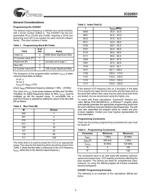
<strong>ICD2051</strong><br />
General Considerations<br />
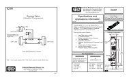
Programming the <strong>ICD2051</strong><br />
The desired output frequency is defined via a serial interface,<br />
with a 22-bin number shifted in. The <strong>ICD2051</strong> has two programmable<br />
PLLs (CLKA and CLKB), requiring a 22-bit programming<br />
word (W) to be loaded into each channel independently.<br />
This word contains 5 fields:<br />
Table 1. Programming Word Bit Fields<br />
Field<br />
# of<br />
bits<br />
Notes<br />
Index (I) 4 MSB (Most Significant Bits)<br />
P Counter value (P’) 7<br />
Reserved (R) 1 normally set to logic 1<br />
Mux (M) 3<br />
Q Counter value (Q’) 7 LSB (Least Significant Bits)<br />
The frequency of the programmable oscillator f (VCO) is determined<br />
by these fields as follows:<br />
P’=P−3<br />
Q’=Q−2<br />
f (VCO) =2 x f (REF) x P/Q<br />
where f (REF) =Reference frequency (between 1 MHz − 25 MHz)<br />
The value of f (VCO) must remain between 40 MHz and 120 MHz.<br />
Therefore, for output frequencies below 40 MHz, f (VCO) must be<br />
multiplied up into the required range. To accomplish this, a<br />
post-VCO Divisor is selected by setting the values of the Mux field<br />
(M) as follows:<br />
Table 2. Mux Field (M)<br />
M<br />
Divisor<br />
000 1<br />
001 2<br />
010 4<br />
011 8<br />
100 16<br />
101 32<br />
110 64<br />
111 128<br />
The Index field (I) is used to preset the VCO to an appropriate<br />
range. The value for this field should be should be chosen from<br />
Table 3. (Note that this table is referenced to the VCO frequency<br />
f (VCO) , rather than to the desired output frequency.)<br />
Table 3. Index Field (I)<br />
I<br />
f (VCO) (MHz)<br />
0000 40.0 − 42.5<br />
0001 42.5 − 47l.5<br />
0010 47.5 − 53.5<br />
0011 53.5 − 58.5<br />
0100 58.5 − 62.5<br />
0101 62.5 − 68.5<br />
0110 68.5 − 69.0<br />
0111 69.0 − 82.0<br />
1000 82.0 − 87.0<br />
1001 87.0 − 92.0<br />
1010 92.0 − 92.1<br />
1011 92.1 − 105.0<br />
1100 105.0 − 115.0<br />
1101 115.0 − 120.0<br />
1110 115.0 − 120.0<br />
1111 115.0 − 120.0<br />
If the desired VCO frequency lies on a boundary in the table<br />
(if it is exactly the upper limit of one entry and the lower limit of<br />
the next) then either index value may be used (since both limits<br />
are tested), but we recommend using the higher one.<br />
To assist with these calculations, Cypress/IC Designs provides<br />
BitCalc (Part #ICD/BCALC), a Windows program which<br />
automatically generates the appropriate programming words from<br />
the user’s reference input and desired output frequencies. The software<br />
also assembles the program words for control and power-down<br />
registers. Contact your local Cypress representative for<br />
more information.<br />
Programming Constraints<br />
There are five primary programming constraints the user must<br />
be aware of:<br />
Table 4. Programming Constraints<br />
Parameter Minimum Maximum<br />
f (REF) 1 MHz 25 MHz<br />
f (REF) /Q 200 kHz 1 MHz<br />
f (VCO) 40 MHz 120 MHz<br />
Q 3 129<br />
P 4 130<br />
The constraints have to do with trade-offs between optimum<br />
speed and lowest noise, VCO stability and factors affecting the<br />
loop equation. The factors are listed for completeness sake;<br />
however, by using the BitCalc program all of these constraints<br />
become transparent.<br />
<strong>ICD2051</strong> Programming Example<br />
The following is an example of the calculations BitCalc performs:<br />
3