IBX-650A_UMN_v1.00.pdf - ICP America
IBX-650A_UMN_v1.00.pdf - ICP America
IBX-650A_UMN_v1.00.pdf - ICP America

Create successful ePaper yourself
Turn your PDF publications into a flip-book with our unique Google optimized e-Paper software.
<strong>IBX</strong>-<strong>650A</strong> Embedded System<br />
Page 1<br />
<strong>IBX</strong>-<strong>650A</strong> Embedded System
<strong>IBX</strong>-<strong>650A</strong> Embedded System<br />
Revision<br />
<strong>IBX</strong>-<strong>650A</strong> Embedded System<br />
Date Version Changes<br />
August 2007 1.00 Initial release<br />
Page 2
<strong>IBX</strong>-<strong>650A</strong> Embedded System<br />
Page 3<br />
Copyright<br />
COPYRIGHT NOTICE<br />
The information in this document is subject to change without prior notice in order to<br />
improve reliability, design and function and does not represent a commitment on the part<br />
of the manufacturer.<br />
In no event will the manufacturer be liable for direct, indirect, special, incidental, or<br />
consequential damages arising out of the use or inability to use the product or<br />
documentation, even if advised of the possibility of such damages.<br />
This document contains proprietary information protected by copyright. All rights are<br />
reserved. No part of this manual may be reproduced by any mechanical, electronic, or<br />
other means in any form without prior written permission of the manufacturer.<br />
TRADEMARKS<br />
IBM PC is a registered trademark of International Business Machines Corporation.<br />
INTEL® is a registered trademark of INTEL® Corporation. Other product names<br />
mentioned herein are used for identification purposes only and may be trademarks and/or<br />
registered trademarks of their respective owners.
<strong>IBX</strong>-<strong>650A</strong> Embedded System<br />
Packing List<br />
NOTE:<br />
If any of the components listed in the checklist below are missing, please do not<br />
proceed with the installation. Contact the IEI reseller or vendor you purchased<br />
the <strong>IBX</strong>-<strong>650A</strong> from or contact an IEI sales representative directly. To contact an<br />
IEI sales representative, please send an email to sales@iei.com.tw.<br />
The items listed below should all be included in the <strong>IBX</strong>-<strong>650A</strong> package.<br />
• 1 x <strong>IBX</strong>-<strong>650A</strong> embedded system<br />
• 1 x Power Adapter<br />
• 1 x Power cord<br />
• 1 x Screw set<br />
• 1 x Thermal pad for HDD<br />
• 4 x Foot pads<br />
• 1 x Wall mount kit<br />
• 1 x QIG<br />
• 1 x Driver and manual CD<br />
• 1 x DIN mount kit (optional)<br />
Page 4
<strong>IBX</strong>-<strong>650A</strong> Embedded System<br />
Page 5<br />
Precautions<br />
SAFETY PRECAUTIONS<br />
1. Prior to installing, moving and modifying the embedded system, make sure<br />
that the unit’s power is turned off and the power cord is disconnected.<br />
2. Do not apply voltage levels that exceed the specified voltage range. Doing so<br />
may cause fire or an electrical shock.<br />
3. Electric shock can occur if the embedded system is opened. Do not drop or<br />
insert any objects into any openings of the embedded system.<br />
4. Only qualified engineers from certified system integrators or VARs are<br />
allowed to make necessary modifications to the embedded system.<br />
5. If considerable amounts of dust, water, or fluids enter the embedded system,<br />
turn off the power supply immediately, unplug the power cord, and contact the<br />
vendor.<br />
6. Explosions may occur with installations in environments where flammable<br />
gases are present.<br />
7. Fault-tolerant and failsafe designs should be implemented with the use of the<br />
embedded system on transportation vehicles, ships, safety/security devices,<br />
or medical devices not related to life-support functions. Users/integrators<br />
should take responsibility for adequate levels of reliability and safety.<br />
8. Preventive designs should be implemented so as to avoid communications<br />
faults between the embedded system and the devices it controls.0.<br />
HANDLING PRECAUTIONS<br />
1. Do not drop the embedded system against a hard surface.<br />
2. Do not strike or exert excessive force onto the embedded system.<br />
3. Avoid exposing the embedded system to direct sunlight, dust, or chemical<br />
vapors.<br />
4. Condensation might form inside the embedded system chassis if exposed to<br />
sudden changes in temperature.<br />
5. Carefully route the power cord so that people cannot step on it. Do not place<br />
anything over the power cord.
<strong>IBX</strong>-<strong>650A</strong> Embedded System<br />
6. If the equipment should be left unused for an extended period of time,<br />
disconnect it from the power source to avoid damage by transient<br />
over-voltage.<br />
7. If any of the following situations arises, get the equipment checked by service<br />
personnel:0.<br />
o The power cord or plug is damaged.<br />
o Liquid has penetrated into the equipment.<br />
o The equipment has been exposed to moisture.<br />
o The equipment does not work properly, or the user cannot get it to work<br />
according to the user manual.<br />
o The equipment has been dropped and damaged.<br />
o The equipment shows obvious signs of breakage.<br />
WARNING!<br />
Any changes or modifications made to the equipment that are not<br />
expressly approved by the relevant standards could void the authority<br />
to operate the equipment.<br />
MAINTENANCE AND CLEANING<br />
Note the following precautions before beginning to clean the embedded system.<br />
When cleaning any single part or component of the computer, please read and<br />
understand the details below fully.<br />
• Never spray or squirt liquids directly onto any computer component. To clean<br />
the device, please rub it with a piece of dry and soft cloth or a slightly<br />
moistened cloth.<br />
• The interior of the embedded system does not require cleaning. Keep fluids<br />
away from the embedded system and the interior of it.<br />
• Turn the system off before cleaning the embedded system.<br />
• Never drop any objects through the openings of the embedded system or get<br />
the circuit board damp or wet.<br />
Page 6
<strong>IBX</strong>-<strong>650A</strong> Embedded System<br />
Page 7<br />
• Be cautious of any cleaning solvents or chemicals used when cleaning the<br />
embedded system as some individuals may be allergic to the ingredients.<br />
• Avoid any eating, drinking or smoking near the embedded system.<br />
CLEANING TOOLS<br />
Below is a list of items to use while cleaning the computer or computer peripherals. Please<br />
keep in mind that some components in the computer may only be cleaned using a product<br />
designed for cleaning that component, if this is the case it will be mentioned in the<br />
cleaning tips.<br />
• Cloth - A piece of cloth is the best tool to use when rubbing up a component.<br />
Although paper towels or tissues can be used on most hardware as well, it is<br />
recommended to rub it with a piece of cloth.<br />
• Water or rubbing alcohol – Moisten a piece of cloth a bit with some water or<br />
rubbing alcohol and rub it on the computer. Unknown solvents may be harmful<br />
to the plastics parts.<br />
• Vacuum cleaner - Removing the dust, dirt, hair, cigarette particles, and other<br />
particles out of a computer can be one of the best methods of cleaning a<br />
computer. Over time these items can restrict the airflow in a computer and<br />
cause circuitry to corrode.<br />
• Cotton swabs - Cotton swabs moistened with rubbing alcohol or water are<br />
excellent tools for wiping hard to reach areas in the keyboard, mouse, and<br />
other locations.<br />
• Foam swabs - Whenever possible it is better to use lint free swabs such as<br />
foam swabs.<br />
ESD PRECAUTIONS<br />
Observe all conventional anti-ESD methods while handling the components contained<br />
within the embedded system should the need arise to remove any of the chassis panels.<br />
The use of a grounded wrist strap and an anti-static work pad is recommended. Avoid dust<br />
and debris or other static-accumulating materials in the work area.
<strong>IBX</strong>-<strong>650A</strong> Embedded System<br />
Table of Contents<br />
1 INTRODUCTION................................................................................................... 19<br />
1.1 <strong>IBX</strong>-<strong>650A</strong> EMBEDDED SYSTEM OVERVIEW............................................................. 20<br />
1.1.1 <strong>IBX</strong>-<strong>650A</strong> Benefits............................................................................................ 20<br />
1.1.2 <strong>IBX</strong>-<strong>650A</strong> Features........................................................................................... 20<br />
1.2 TECHNICAL SPECIFICATIONS .................................................................................... 21<br />
1.3 POWER MODULE SPECIFICATIONS............................................................................ 22<br />
1.4 POWER ADAPTER ..................................................................................................... 23<br />
2 MECHANICAL DESCRIPTION.......................................................................... 25<br />
2.1 <strong>IBX</strong>-<strong>650A</strong> MECHANICAL OVERVIEW....................................................................... 26<br />
2.2 PHYSICAL DIMENSIONS............................................................................................ 26<br />
2.2.1 <strong>IBX</strong>-<strong>650A</strong> Dimensions...................................................................................... 26<br />
2.2.2 Motherboard Dimensions ................................................................................ 27<br />
2.2.3 Power Module Dimensions.............................................................................. 28<br />
2.3 EXTERNAL OVERVIEW ............................................................................................. 29<br />
2.3.1 Front Panel ...................................................................................................... 29<br />
2.3.2 Rear Panel ....................................................................................................... 29<br />
2.3.3 Bottom Surface................................................................................................. 30<br />
2.4 INTERNAL OVERVIEW............................................................................................... 31<br />
3 SYSTEM COMPONENTS .................................................................................... 33<br />
3.1 <strong>IBX</strong>-<strong>650A</strong> EMBEDDED SYSTEM MOTHERBOARD..................................................... 34<br />
3.1.1 <strong>IBX</strong>-<strong>650A</strong> Embedded System Motherboard ..................................................... 34<br />
3.1.2 Enano-8523T Motherboard Overview ............................................................. 34<br />
3.1.3 CPU Support.................................................................................................... 35<br />
3.1.4 Intel ® Celeron ® M............................................................................................ 35<br />
3.2 PERIPHERAL INTERFACE CONNECTORS .................................................................... 36<br />
3.2.1 Peripheral Interface Connectors ..................................................................... 36<br />
3.2.2 External Interface Panel Connectors............................................................... 36<br />
3.3 INTERNAL PERIPHERAL CONNECTORS...................................................................... 37<br />
3.3.1 ATX Power Connector ..................................................................................... 37<br />
Page 8
<strong>IBX</strong>-<strong>650A</strong> Embedded System<br />
Page 9<br />
3.3.2 Battery Connector............................................................................................ 38<br />
3.3.3 Compact Flash Type 2 Socket .......................................................................... 39<br />
3.3.4 Front Panel Connector .................................................................................... 40<br />
3.3.5 IDE Connector................................................................................................. 41<br />
3.3.6 Keyboard/Mouse Connector ............................................................................ 43<br />
3.3.7 Parallel Port Connector .................................................................................. 44<br />
3.3.8 Power Connector ............................................................................................. 45<br />
3.3.9 SO-DIMM Socket............................................................................................. 46<br />
3.3.10 USB Connector .............................................................................................. 47<br />
3.4 EXTERNAL PERIPHERAL INTERFACE CONNECTORS .................................................. 48<br />
3.4.1 External Peripheral Interface Connector Overview........................................ 48<br />
3.4.2 Serial Port Connectors .................................................................................... 49<br />
3.4.3 USB Connectors............................................................................................... 50<br />
3.4.4 Ethernet Connector.......................................................................................... 50<br />
3.4.5 VGA Connector ................................................................................................ 51<br />
3.4.6 Audio Connector .............................................................................................. 52<br />
3.5 ENANO-8523T MOTHERBOARD ON-BOARD JUMPERS.............................................. 52<br />
3.5.1 Clear CMOS Jumper........................................................................................ 53<br />
3.5.2 CF Card Setup Jumper .................................................................................... 54<br />
3.5.3 LCD Voltage Selection ..................................................................................... 55<br />
3.6 CONNECTOR MAPPINGS ........................................................................................... 56<br />
3.6.1 Power Connector ............................................................................................. 56<br />
3.6.2 ATX Mode Connector....................................................................................... 57<br />
4 INSTALLATION .................................................................................................... 59<br />
4.1 ANTI-STATIC PRECAUTIONS...................................................................................... 60<br />
4.2 INSTALLATION PROCEDURE...................................................................................... 60<br />
4.2.1 Installation Procedure Overview ..................................................................... 60<br />
4.2.2 Unpacking........................................................................................................ 61<br />
4.2.3 Top Cover Removal.......................................................................................... 62<br />
4.2.4 Configure the Jumper Settings......................................................................... 62<br />
4.2.5 IDE Hard Drive Installation............................................................................ 63<br />
4.2.6 CompactFlash® Card Installation .................................................................. 66<br />
4.2.7 Foot Pad Installation ....................................................................................... 67<br />
4.2.8 Mounting the System with Wall Mount Kit....................................................... 67
<strong>IBX</strong>-<strong>650A</strong> Embedded System<br />
4.2.9 DIN Mounting .................................................................................................. 70<br />
4.2.10 Cable Connections......................................................................................... 72<br />
4.3 POWER-ON PROCEDURE .......................................................................................... 73<br />
4.3.1 Installation Checklist ....................................................................................... 73<br />
4.3.2 Power-on Procedure ........................................................................................ 73<br />
5 BIOS SETTINGS.................................................................................................... 75<br />
5.1 INTRODUCTION ........................................................................................................ 76<br />
5.1.1 Starting Setup................................................................................................... 76<br />
5.1.2 Using Setup ...................................................................................................... 76<br />
5.1.3 Getting Help..................................................................................................... 77<br />
5.1.4 Unable to Reboot After Configuration Changes.............................................. 77<br />
5.1.5 BIOS Menu Bar................................................................................................ 77<br />
5.2 MAIN ....................................................................................................................... 78<br />
5.3 ADVANCED............................................................................................................... 79<br />
5.3.1 CPU Configuration.......................................................................................... 80<br />
5.3.2 IDE Configuration ........................................................................................... 81<br />
5.3.2.1 IDE Master, IDE Slave ............................................................................. 83<br />
5.3.3 Super IO Configuration.................................................................................... 89<br />
5.3.4 Hardware Health Configuration...................................................................... 92<br />
5.3.5 ACPI Configuration ......................................................................................... 93<br />
5.3.6 MPS Configuration .......................................................................................... 94<br />
5.3.7 Trusted Computing ........................................................................................... 95<br />
5.3.8 USB Configuration........................................................................................... 97<br />
5.4 BOOT ....................................................................................................................... 99<br />
5.4.1 Boot Settings Configuration............................................................................. 99<br />
5.4.2 Boot Device Priority ...................................................................................... 102<br />
5.4.3 Hard Disk Drives ........................................................................................... 103<br />
5.5 SECURITY............................................................................................................... 104<br />
5.6 CHIPSET ................................................................................................................. 105<br />
5.6.1 NorthBridge Configuration............................................................................ 106<br />
5.7 POWER....................................................................................................................111<br />
5.8 EXIT........................................................................................................................113<br />
6 DRIVER INSTALLATION...................................................................................115<br />
Page 10
<strong>IBX</strong>-<strong>650A</strong> Embedded System<br />
Page 11<br />
6.1 AVAILABLE SOFTWARE DRIVERS .............................................................................116<br />
6.2 CHIPSET DRIVER INSTALLATION..............................................................................116<br />
6.3 REALTEK AUDIO DRIVER INSTALLATION ................................................................119<br />
6.4 INTEL GRAPHICS MEDIA ACCELERATOR DRIVER ................................................... 123<br />
6.5 LAN DRIVER INSTALLATION ................................................................................. 125<br />
7 TROUBLESHOOTING AND MAINTENANCE .............................................. 129<br />
7.1 <strong>IBX</strong>-<strong>650A</strong> SYSTEM MAINTENANCE OVERVIEW..................................................... 130<br />
7.2 SYSTEM TROUBLESHOOTING.................................................................................. 130<br />
7.2.1 The System Doesn’t Turn On.......................................................................... 130<br />
7.2.2 The System Doesn’t Boot Up.......................................................................... 131<br />
7.2.3 More Troubleshooting .................................................................................... 132<br />
7.3 COMPONENT REPLACEMENT PROCEDURE.............................................................. 132<br />
7.3.1 SO-DIMM Replacement................................................................................. 133<br />
A IEI EMBEDDED SYSTEM SERIES.................................................................. 135<br />
A.1 IEI EMBEDDED SYSTEM SERIES............................................................................ 136<br />
A.1.1 Overview........................................................................................................ 136<br />
A.1.2 IEI Embedded System Series ......................................................................... 136<br />
A.1.3 IEI Embedded System Series Variations........................................................ 137<br />
A.2 EMBEDDED SYSTEM SOLUTIONS........................................................................... 137<br />
A.2.1 AMD ® Geode ® LX800 500MHz Solutions..................................................... 137<br />
A.2.2 AMD ® Geode ® GX466 333MHz Solutions.................................................... 138<br />
A.2.3 VIA ® LUKE ® 1GHz Solutions ....................................................................... 138<br />
A.2.4 VIA ® MARK ® 800MHz Solutions .................................................................. 139<br />
A.2.5 Intel ® Celeron ® M 1 GHz Solutions .............................................................. 139<br />
A.2.6 Intel ® Celeron ® M 1.5GHz Solutions ............................................................ 140<br />
A.2.7 Intel ® Pentium ® M 1.6GHz Solutions............................................................ 140<br />
A.2.8 Intel ® Socket 479 Pentium ® /Celeron ® M 2GHz Solutions ............................ 141<br />
A.2.9 LGA 775 Intel ® Pentium ® 4/ Pentium ® D Solutions ..................................... 141<br />
A.2.10 Intel ® Socket 479 Core Duo/Solo Solutions ................................................ 142<br />
B BIOS MENU OPTIONS....................................................................................... 143<br />
B.1 BIOS CONFIGURATION OPTIONS........................................................................... 144<br />
C WATCHDOG TIMER .......................................................................................... 147
<strong>IBX</strong>-<strong>650A</strong> Embedded System<br />
D ADDRESS MAPPING.......................................................................................... 151<br />
D.1 IO ADDRESS MAP ................................................................................................. 152<br />
D.2 1ST MB MEMORY ADDRESS MAP ......................................................................... 153<br />
D.3 IRQ MAPPING TABLE............................................................................................ 153<br />
D.4 DMA CHANNEL ASSIGNMENTS............................................................................. 153<br />
E HAZARDOUS MATERIALS DISCLOSURE ................................................... 155<br />
E.1 HAZARDOUS MATERIAL DISCLOSURE TABLE FOR IPB PRODUCTS CERTIFIED AS<br />
ROHS COMPLIANT UNDER 2002/95/EC WITHOUT MERCURY..................................... 156<br />
8 INDEX.................................................................................................................... 159<br />
Page 12
<strong>IBX</strong>-<strong>650A</strong> Embedded System<br />
Page 13<br />
List of Figures<br />
Figure 1-1: <strong>IBX</strong>-<strong>650A</strong> Embedded System..................................................................20<br />
Figure 1-2: Power Adapter .........................................................................................23<br />
Figure 2-1: <strong>IBX</strong>-<strong>650A</strong> Dimensions (mm)....................................................................27<br />
Figure 2-2: Enano-8523T SBC Dimensions (mm) ....................................................28<br />
Figure 2-3: Power Module Dimensions (mm) ...........................................................28<br />
Figure 2-4: <strong>IBX</strong>-<strong>650A</strong> Front Panel ..............................................................................29<br />
Figure 2-5: <strong>IBX</strong>-<strong>650A</strong> Rear Panel ...............................................................................30<br />
Figure 2-6: Bottom Surface ........................................................................................31<br />
Figure 2-7: Internal Overview.....................................................................................32<br />
Figure 3-1: Enano-8523T Jumper and Connector Locations..................................34<br />
Figure 3-2: ATX Power Connector Location.............................................................38<br />
Figure 3-3: Battery Connector Location ...................................................................38<br />
Figure 3-4: CFII Socket Location (Rear Side) ...........................................................40<br />
Figure 3-5: Front Panel Connector Location............................................................41<br />
Figure 3-6: IDE Connector Location..........................................................................43<br />
Figure 3-7: Keyboard/Mouse Connector Location...................................................44<br />
Figure 3-8: Parallel Port Connector Location...........................................................45<br />
Figure 3-9: Power Connector Location.....................................................................46<br />
Figure 3-10: SO-DIMM Socket Location (Rear Side)................................................47<br />
Figure 3-11: USB Connector Location ......................................................................48<br />
Figure 3-12: Enano-8523T Board Rear Panel ...........................................................49<br />
Figure 3-13: RJ-45 Ethernet Connector ....................................................................51<br />
Figure 3-14: Jumpers..................................................................................................52<br />
Figure 3-15: JP2 Clear CMOS Jumper.......................................................................54<br />
Figure 3-16: CF Card Setup Jumper Location..........................................................55<br />
Figure 3-17: LCD Voltage Selection Jumper Location ............................................56<br />
Figure 4-1: Top Cover Retention Screws..................................................................62<br />
Figure 4-2: Hard Drive Bracket ..................................................................................63
<strong>IBX</strong>-<strong>650A</strong> Embedded System<br />
Figure 4-3:HDD Bracket Retention Screws ..............................................................64<br />
Figure 4-4: HDD Retention Screws............................................................................64<br />
Figure 4-5: HDD Thermal Pad ....................................................................................65<br />
Figure 4-6: CF Card Slot Cover Retention Screws ..................................................66<br />
Figure 4-7: CF Card Installation.................................................................................66<br />
Figure 4-8: Foot Pads Installation .............................................................................67<br />
Figure 4-9: Wall-mounting Bracket............................................................................68<br />
Figure 4-10: Mount the Embedded System ..............................................................69<br />
Figure 4-11: Secure the Embedded System .............................................................70<br />
Figure 4-12: DIN Rail Mounting Bracket....................................................................70<br />
Figure 4-13: Screw Locations ....................................................................................71<br />
Figure 4-14: Mounting the DIN RAIL..........................................................................71<br />
Figure 4-15: Secure the Assembly to the DIN Rail...................................................72<br />
Figure 4-16: Power Button .........................................................................................73<br />
Figure 6-1: InstallShield Wizard Preparation Screen............................................ 117<br />
Figure 6-2: Welcome Screen ................................................................................... 117<br />
Figure 6-3: License Agreement............................................................................... 118<br />
Figure 6-4: Readme Information ............................................................................. 118<br />
Figure 6-5: Restart the Computer........................................................................... 119<br />
Figure 6-6: Audio Driver Install Shield Wizard Starting ....................................... 120<br />
Figure 6-7: Audio Driver Setup Preparation .......................................................... 120<br />
Figure 6-8: Audio Driver Welcome Screen ............................................................ 121<br />
Figure 6-9: Audio Driver Software Configuration ................................................. 121<br />
Figure 6-10: Audio Driver Digital Signal ................................................................ 122<br />
Figure 6-11: Audio Driver Installation Begins ....................................................... 122<br />
Figure 6-12: Audio Driver Installation Complete................................................... 123<br />
Figure 6-13: GMA Driver Installation Welcome Screen........................................ 124<br />
Figure 6-14: GMA Driver License Agreement........................................................ 124<br />
Figure 6-15: GMA Driver Installing Notice ............................................................. 125<br />
Figure 6-16: GMA Driver Installation Complete .................................................... 125<br />
Figure 6-17: LAN License Agreement .................................................................... 126<br />
Figure 6-18: Select the Driver Directory ................................................................ 126<br />
Page 14
<strong>IBX</strong>-<strong>650A</strong> Embedded System<br />
Page 15<br />
Figure 6-19: LAN Driver Configuration .................................................................. 127<br />
Figure 7-1: SO-DIMM Access Panel........................................................................ 133<br />
Figure 7-2: SO-DIMM Installation............................................................................ 134
<strong>IBX</strong>-<strong>650A</strong> Embedded System<br />
List of Tables<br />
Table 1-1: Technical Specifications ..........................................................................22<br />
Table 1-2: DC-to-DC Power Module Specifications .................................................23<br />
Table 1-3: Power Adapter Specifications..................................................................24<br />
Table 3-1: Supported Processor................................................................................35<br />
Table 3-2: Peripheral Interface Connectors..............................................................36<br />
Table 3-3: Rear Panel Connectors.............................................................................37<br />
Table 3-4: ATX Power Connector Pinouts ................................................................37<br />
Table 3-5: CFII Socket Pinouts...................................................................................40<br />
Table 3-6: Front Panel Connector Pinouts ...............................................................41<br />
Table 3-7: IDE Connector Pinouts .............................................................................42<br />
Table 3-8: Keyboard/Mouse Connector Pinouts ......................................................43<br />
Table 3-9: Parallel Port Connector Pinouts ..............................................................45<br />
Table 3-10: Power Connector Pinouts ......................................................................46<br />
Table 3-11: USB Connector Pinouts..........................................................................47<br />
Table 3-12: Serial Port Pinouts ..................................................................................49<br />
Table 3-13: USB Connectors......................................................................................50<br />
Table 3-14: RJ-45 Ethernet Connector Pinouts........................................................51<br />
Table 3-15: RJ-45 Ethernet Connector LEDs............................................................51<br />
Table 3-16: VGA Connector Pinouts .........................................................................52<br />
Table 3-17: Jumpers....................................................................................................53<br />
Table 3-18: JP2 Clear CMOS Jumper Settings.........................................................54<br />
Table 3-19: CF Card Setup Jumper Settings ............................................................55<br />
Table 3-20: LCD Voltage Selection Jumper Settings...............................................56<br />
Table 3-21: Motherboard Power Connector Mapping..............................................57<br />
Table 3-22: Motherboard ATX Power Connector Mapping .....................................57<br />
Table 4-1: Package List Contents..............................................................................62<br />
Table 5-1: BIOS Navigation Keys...............................................................................77<br />
Page 16
<strong>IBX</strong>-<strong>650A</strong> Embedded System<br />
Page 17<br />
List of BIOS Menus<br />
Menu 1: Main ....................................................................................................78<br />
Menu 2: Advanced ....................................................................................................80<br />
Menu 3: CPU Configuration .......................................................................................81<br />
Menu 4: IDE Configuration .........................................................................................82<br />
Menu 5: IDE Master and IDE Slave Configuration ...................................................84<br />
Menu 6: Super IO Configuration ................................................................................89<br />
Menu 7: Hardware Health Configuration ..................................................................93<br />
Menu 8: ACPI Configuration ......................................................................................94<br />
Menu 9: MPS Configuration .......................................................................................95<br />
Menu 10: Trusted Computing.....................................................................................96<br />
Menu 11: USB Configuration .....................................................................................97<br />
Menu 12: Boot ....................................................................................................99<br />
Menu 13: Boot Settings Configuration................................................................... 100<br />
Menu 14: Boot Device Priority Settings................................................................. 103<br />
Menu 15: Security ................................................................................................. 104<br />
Menu 16: Chipset ................................................................................................. 105<br />
Menu 17:NorthBridge Chipset Configuration........................................................ 106<br />
Menu 18:Power ................................................................................................. 111<br />
Menu 19:Exit ................................................................................................. 113
<strong>IBX</strong>-<strong>650A</strong> Embedded System<br />
THIS PAGE IS INTENTIONALLY LEFT BLANK<br />
Page 18
<strong>IBX</strong>-<strong>650A</strong> Embedded System<br />
Page 19<br />
Chapter<br />
1<br />
1 Introduction
1.1 <strong>IBX</strong>-<strong>650A</strong> Embedded System Overview<br />
<strong>IBX</strong>-<strong>650A</strong> Embedded System<br />
Figure 1-1: <strong>IBX</strong>-<strong>650A</strong> Embedded System<br />
<strong>IBX</strong>-<strong>650A</strong> is an Intel® Celeron® M based embedded solutions with IEI Enano-8523T<br />
motherboard. The fanless motherboard has been optimized for multimedia applications that<br />
require minimum installation space. The Enano-8523T motherboard supports a full range of<br />
functions for an AT/ATX-compatible industrial computer. <strong>IBX</strong>-<strong>650A</strong> embedded subsystem is<br />
capable of supporting one 2.5” hard disk drive.<br />
1.1.1 <strong>IBX</strong>-<strong>650A</strong> Benefits<br />
The <strong>IBX</strong>-<strong>650A</strong> embedded system has the following benefits:<br />
• Easy installation saves installation time<br />
• Complete integration saves solution development time and cost<br />
• Secure storage with one IDE hard drive supported<br />
• Compact size saves space<br />
• Powerful preinstalled Intel® Celeron M CPU and motherboard ensures<br />
rigorous processing needs can be met<br />
1.1.2 <strong>IBX</strong>-<strong>650A</strong> Features<br />
The <strong>IBX</strong>-<strong>650A</strong> has the following features<br />
• RoHS compliant design<br />
• Fanless system<br />
• Built-in DC-to-DC power converter<br />
Page 20
<strong>IBX</strong>-<strong>650A</strong> Embedded System<br />
Page 21<br />
• Intel® Celeron M 1GHz Zero Cache CPU supported<br />
• One 10/100Base-T Ethernet connector for network applications<br />
• One IDE hard drive supported<br />
• Wall mount and DIN mount supported.<br />
1.2 Technical Specifications<br />
The specifications for the Intel based embedded systems are listed below.<br />
<strong>IBX</strong>-<strong>650A</strong><br />
CPU<br />
System Chipset<br />
System Memory<br />
Ethernet<br />
Display<br />
IO<br />
Intel ® ULV Celeron ® M 1GHz zero cache CPU<br />
Intel® 852GM + ICH4<br />
512MB 200-pin SO-DIMM DDR SDRAM preinstalled<br />
One 10/100Base-T Intel 82562ET<br />
CRT integrated in Intel® 852GM<br />
4 x USB 2.0 supported (two in front panel, two in rear panel)<br />
3 x RS-232<br />
3 x Audio jacks (Line-In, Line-Out, MIC)<br />
1 x Parallel port<br />
1 x VGA connector<br />
1 x RJ-45 Ethernet connector<br />
1 x Keyboard connector<br />
1 x Mouse connector<br />
Storage<br />
One 2.5” IDE hard drive supported<br />
One CompactFlash® card slot supported<br />
Chassis Construction<br />
Power Supply<br />
Aluminum<br />
Internal DC-to-DC power converter, input voltage: 12V DC<br />
External power adapter, input voltage:<br />
90V AC ~ 264V AC @ 47Hz ~ 63Hz, 55W
<strong>IBX</strong>-<strong>650A</strong> Embedded System<br />
Operating Shock<br />
Operating Shock Half-Sine Wave Shock<br />
3G: 11ms: 3 shocks per axis: Vertical/Transverse/Longitudinal.<br />
Non-Operation Shock Half-Sine Wave Shock<br />
10G: 11ms: 3 shocks per axis: Vertical/Transverse/Longitudinal.<br />
Operating Vibration<br />
1G, 5Hz~500Hz, random operation (HDD)<br />
Operating temperature 0ºC ~ 50ºC<br />
Color<br />
Weight (Net)<br />
Dimensions (D x W x H)<br />
EMC<br />
Black<br />
2.75kg<br />
170mm x 210.2mm x 68.75mm<br />
UL / CE/ EMC / FCC<br />
Table 1-1: Technical Specifications<br />
1.3 Power Module Specifications<br />
The IDD-12250A power module installed in the <strong>IBX</strong>-<strong>650A</strong> embedded system supports a<br />
12V DC input. The specifications for the IDD-12250A are shown in Table 1-2.<br />
Model Name:<br />
Input<br />
IDD-12250A<br />
12VDC<br />
Output<br />
12V<br />
5V<br />
5VSB<br />
Max. Total Output:<br />
5A (pass thru.)<br />
10A (Max.)<br />
0.5A (Max.)<br />
50W+60W (12V pass thru.)<br />
Performance Characteristics<br />
Noise & Ripple:<br />
< 25mV<br />
Page 22
<strong>IBX</strong>-<strong>650A</strong> Embedded System<br />
Page 23<br />
Load Regulation<br />
<strong>IBX</strong>-<strong>650A</strong> Embedded System<br />
Over-Voltage Upper Trip Limit: 15V+/-1.5V<br />
Time Hold Up 10ms<br />
Input<br />
Min.<br />
Nominal<br />
Max.<br />
Frequency<br />
Inrush Current<br />
Steady Current<br />
Efficiency<br />
90V<br />
115V ~ 230V<br />
264V<br />
47Hz ~ 63Hz<br />
80A Max. (cold start at 25ºC)<br />
1.3Arms Max.<br />
80% (typical)<br />
Temperature<br />
Operating 0ºC ~ 40ºC<br />
Storage -25ºC ~ 65ºC<br />
Relative Humidity<br />
Operating<br />
(non-condensing)<br />
Storage<br />
0% ~ 95%<br />
0% ~ 95%<br />
Environment<br />
(non-condensing)<br />
Operating: 1G, 5Hz~500Hz, random vibration,<br />
Vibration<br />
30mins/axis, 3 direction<br />
Storage: 2G, 5Hz~500Hz, random vibration,<br />
30mins/axis, 3 direction<br />
Shock<br />
Operating: 10G, 11ms, Half-sine wave<br />
Storage: 20G, 11ms, Half-sine wave<br />
Reliability<br />
MTBF 100,000 hours of continuous operation at 25ºC<br />
Leakage Current<br />
0.5mA max @264V<br />
Table 1-3: Power Adapter Specifications<br />
Page 24
<strong>IBX</strong>-<strong>650A</strong> Embedded System<br />
Page 25<br />
Chapter<br />
2<br />
2 Mechanical<br />
Description
<strong>IBX</strong>-<strong>650A</strong> Embedded System<br />
2.1 <strong>IBX</strong>-<strong>650A</strong> Mechanical Overview<br />
The <strong>IBX</strong>-<strong>650A</strong> RoHS compliant, Intel® Celeron® M fanless embedded system features<br />
industrial grade components that offer longer operating life, high vibration resistance and<br />
endurance over a wide temperature range. The <strong>IBX</strong>-<strong>650A</strong> combines these features in an<br />
aluminum enclosure designed for space critical applications that require low power<br />
consumption. Featuring four USB, three serial communication ports, three audio jacks, as<br />
well as LAN, parallel port, keyboard, mouse and VGA, the <strong>IBX</strong>-<strong>650A</strong> offers system<br />
integrators and developers the best selection of robust and high performance computing<br />
system platforms. An internal bracket supports one 2.5” IDE hard drives.<br />
2.2 Physical Dimensions<br />
The physical dimensions of the <strong>IBX</strong>-<strong>650A</strong> embedded systems are listed below.<br />
2.2.1 <strong>IBX</strong>-<strong>650A</strong> Dimensions<br />
The dimensions of the <strong>IBX</strong>-<strong>650A</strong> are listed below and shown in Figure 2-1.<br />
• Height: 68.75mm<br />
• Width: 210.20mm<br />
• Length: 170.00mm<br />
Page 26
<strong>IBX</strong>-<strong>650A</strong> Embedded System<br />
Page 27<br />
Figure 2-1: <strong>IBX</strong>-<strong>650A</strong> Dimensions (mm)<br />
2.2.2 Motherboard Dimensions<br />
The Enano-8523T motherboard dimension are listed below and shown in Figure 2-2.<br />
• Length: 115.00mm<br />
• Width: 165.00mm
<strong>IBX</strong>-<strong>650A</strong> Embedded System<br />
Figure 2-2: Enano-8523T SBC Dimensions (mm)<br />
2.2.3 Power Module Dimensions<br />
The power module dimensions are listed below and shown in Figure 2-3.<br />
• Length: 100.00mm<br />
• Width: 40.00mm<br />
Figure 2-3: Power Module Dimensions (mm)<br />
Page 28
<strong>IBX</strong>-<strong>650A</strong> Embedded System<br />
Page 29<br />
2.3 External Overview<br />
2.3.1 Front Panel<br />
The <strong>IBX</strong>-<strong>650A</strong> front panel contains:<br />
• 2 x USB port connectors<br />
• 1 x HDD LED indicator<br />
• 1 x Power button<br />
An overview of the front panel is shown in Figure 2-4 below.<br />
Figure 2-4: <strong>IBX</strong>-<strong>650A</strong> Front Panel<br />
2.3.2 Rear Panel<br />
The rear panel of the <strong>IBX</strong>-<strong>650A</strong> provides access to the following external I/O connectors.<br />
• 3 x RS-232 serial ports<br />
• 1 x Parallel port<br />
• 1 x VGA connector<br />
• 1 x RJ-45 Ethernet connector<br />
• 2 x USB port connectors<br />
• 3 x Audio jacks<br />
• 1 x Keyboard connector<br />
• 1 x Mouse connector<br />
• 1 x 12V DC power jack<br />
• 1 x Reset button
<strong>IBX</strong>-<strong>650A</strong> Embedded System<br />
An overview of the rear panel is shown in Figure 2-5.<br />
Figure 2-5: <strong>IBX</strong>-<strong>650A</strong> Rear Panel<br />
2.3.3 Bottom Surface<br />
WARNING:<br />
Never remove the bottom access panel from the chassis while power is still<br />
being fed into the system. Before removing the bottom access panel, make<br />
sure the system has been turned off and all power connectors unplugged.<br />
The bottom surface of the <strong>IBX</strong>-<strong>650A</strong> contains the retention screw holes for the VESA<br />
MIS-D 75 wall-mount kit, the DIN mount bracket and four foot pads. The SO-DIMM socket<br />
access panel is also located on the bottom surface. The SO-DIMM socket access panel is<br />
secured to the <strong>IBX</strong>-<strong>650A</strong> with one retention screw.<br />
Page 30
<strong>IBX</strong>-<strong>650A</strong> Embedded System<br />
Page 31<br />
Figure 2-6: Bottom Surface<br />
2.4 Internal Overview<br />
The <strong>IBX</strong>-<strong>650A</strong> internal components are listed below:<br />
• 1 x IEI Enano-8523T motherboard (preinstalled)<br />
• 1 x IEI IDD-12250A power module (preinstalled)<br />
• 1 x SO-DIMM module (preinstalled)<br />
• 1 x Hard drive bracket and IDE cable support one IDE hard disk<br />
Except for the SO-DIMM module, all the components are accessed by removing the top<br />
cover. The SO-DIMM module is accessed through the access panel on the bottom<br />
surface.
<strong>IBX</strong>-<strong>650A</strong> Embedded System<br />
Figure 2-7: Internal Overview<br />
Page 32
<strong>IBX</strong>-<strong>650A</strong> Embedded System<br />
Page 33<br />
Chapter<br />
3<br />
3 System Components
3.1 <strong>IBX</strong>-<strong>650A</strong> Embedded System Motherboard<br />
3.1.1 <strong>IBX</strong>-<strong>650A</strong> Embedded System Motherboard<br />
<strong>IBX</strong>-<strong>650A</strong> Embedded System<br />
NOTE:<br />
The jumpers and connectors shown in the section below are those jumpers<br />
and connectors that are relevant to the configuration and installation of the<br />
embedded system. For a complete list of jumpers and connectors on the<br />
Enano-8523T motherboard, please refer to the Enano-8523T user manual.<br />
The <strong>IBX</strong>-<strong>650A</strong> models have an Enano-8523T motherboard installed in the system. The<br />
following sections describe the relevant connectors and jumpers on the motherboard.<br />
3.1.2 Enano-8523T Motherboard Overview<br />
The locations of the Enano-8523T jumpers and connectors used on the <strong>IBX</strong>-<strong>650A</strong> are<br />
shown in Figure 3-1 below.<br />
Figure 3-1: Enano-8523T Jumper and Connector Locations<br />
Page 34
<strong>IBX</strong>-<strong>650A</strong> Embedded System<br />
Page 35<br />
3.1.3 CPU Support<br />
NOTE:<br />
The <strong>IBX</strong>-<strong>650A</strong> has a preinstalled 1GHz Celeron M CPU on-board. If the<br />
CPU fails, the motherboard has to be replaced. Please contact the IEI<br />
reseller or vendor you purchased the <strong>IBX</strong>-<strong>650A</strong> from or contact an IEI<br />
sales representative directly. To contact an IEI sales representative,<br />
please send an email to sales@iei.com.tw.<br />
The ULV Intel ® Celeron ® M processor is installed on the Enano-8523T motherboard.<br />
Specifications for the processor are listed in Table 3-1 below:<br />
Family Architecture Cache Clock Speed FSB<br />
ULV Intel® Celeron ® M 90 nm 512 KB L2 1.0 GHz 400 MHz<br />
Table 3-1: Supported Processor<br />
3.1.4 Intel ® Celeron ® M<br />
The (ULV) Intel® Celeron® M processor comes with the following features:<br />
• Intel® Streaming SIMD Extensions accelerates 3D graphics performance,<br />
video decoding/encoding, and speech recognition.<br />
• Advanced power management features<br />
• Compatible with IA-32 software<br />
• Advanced branch prediction and data prefetch logic
<strong>IBX</strong>-<strong>650A</strong> Embedded System<br />
3.2 Peripheral Interface Connectors<br />
Section 3.2.1 lists all the peripheral interface connectors seen in Section 3.1.2.<br />
3.2.1 Peripheral Interface Connectors<br />
Table 3-2 shows a list of the peripheral interface connectors on the Enano-8523T.<br />
Detailed descriptions of these connectors can be found in Section 3.3.<br />
Label Connector Type<br />
ATX power connector 3-pin wafer connector PW2<br />
Battery connector 2-pin wafer connector BT1<br />
CF Card Type II connector (solder side) 50-pin CF slot CN7<br />
Front panel connector 12-pin header CN12<br />
HDD connector 44-pin box header IDE1<br />
Keyboard/Mouse connector 6-pin wafer connector KB_MS1<br />
Parallel port connector 26-pin header CN2<br />
Power connector 4-pin wafer connector PW1<br />
SO-DIMM slot (solder side) 200-pin slot DIMM1<br />
USB 2.0 connector for two USB devices 8-pin header USB1<br />
Table 3-2: Peripheral Interface Connectors<br />
3.2.2 External Interface Panel Connectors<br />
Table 3-3 lists the rear panel connectors on the Enano-8523T. Detailed descriptions of<br />
these connectors can be found in Section 3.4.<br />
Page 36
<strong>IBX</strong>-<strong>650A</strong> Embedded System<br />
Page 37<br />
Connector Type Label<br />
Audio connector Audio jack CN11<br />
Ethernet connectors<br />
Two USB ports<br />
RJ-45 connector<br />
USB port<br />
J15<br />
COM1 and COM2 serial port connector DB-9 connector J5<br />
COM3 serial port connector DB-9 connector CN6<br />
VGA port connector 15-pin female CN1<br />
Table 3-3: Rear Panel Connectors<br />
3.3 Internal Peripheral Connectors<br />
Internal peripheral connectors are found on the motherboard and are only accessible<br />
when the motherboard is outside of the chassis. This section has complete descriptions of<br />
all the internal, peripheral connectors on the Enano-8523T.<br />
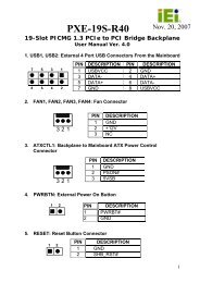
3.3.1 ATX Power Connector<br />
CN Label:<br />
CN Type:<br />
PW2<br />
3-pin wafer connector (1x3)<br />
CN Location: See Figure 3-2<br />
CN Pinouts: See Table 3-4<br />
PIN NO.<br />
DESCRIPTION<br />
1 5VSBY<br />
2 GND<br />
3 PSON<br />
Table 3-4: ATX Power Connector Pinouts
<strong>IBX</strong>-<strong>650A</strong> Embedded System<br />
Figure 3-2: ATX Power Connector Location<br />
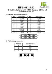
3.3.2 Battery Connector<br />
CN Label:<br />
CN Type:<br />
BT1<br />
2-pin wafer connector (1x2)<br />
CN Location: See Figure 3-3<br />
The battery connector is connected to a preinstalled VARTA CR2032 3V battery.<br />
Figure 3-3: Battery Connector Location<br />
Page 38
<strong>IBX</strong>-<strong>650A</strong> Embedded System<br />
Page 39<br />
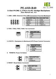
3.3.3 Compact Flash Type 2 Socket<br />
CN Label:<br />
CN Type:<br />
CN7<br />
50-pin CF slot<br />
CN Location: See Figure 3-4<br />
CN Pinouts: See Table 3-5<br />
A CFII (CompactFlash® type II connector) is located on the rear side of the Enano-8523T.<br />
The CFII connector is for applications without external storage. The Compact Flash socket<br />
provides an alternative to hard disk drives in applications where hard disk drives may<br />
consume too much space and storage capacity is not a requirement. The CF card<br />
behaves like a Secondary IDE Master disk drive.<br />
PIN DESCRIPTION PIN DESCRIPTION<br />
1 GROUND 26 VCC-IN CHECK1<br />
2 DATA 3 27 DATA 11<br />
3 DATA 4 28 DATA 12<br />
4 DATA 5 29 DATA 13<br />
5 DATA 6 30 DATA 14<br />
6 DATA 7 31 DATA 15<br />
7 HDC_CS0# 32 HDC_CS1<br />
8 N/C 33 N/C<br />
9 GROUND 34 IOR#<br />
10 N/C 35 IOW#<br />
11 N/C 36 VCC_COM<br />
12 N/C 37 IRQ15<br />
13 VCC_COM 38 VCC_COM<br />
14 N/C 39 CSEL<br />
15 N/C 40 N/C<br />
16 N/C 41 HDD_RESET<br />
17 N/C 42 IORDY<br />
18 SA2 43 SDREQ
<strong>IBX</strong>-<strong>650A</strong> Embedded System<br />
19 SA1 44 SDACK#<br />
20 SA0 45 HDD_ACTIVE#<br />
21 DATA 0 46 66DET<br />
22 DATA 1 47 DATA 8<br />
23 DATA 2 48 DATA 9<br />
24 N/C 49 DATA 10<br />
25 VCC-IN CHECK2 50 GROUND<br />
Table 3-5: CFII Socket Pinouts<br />
Figure 3-4: CFII Socket Location (Rear Side)<br />
3.3.4 Front Panel Connector<br />
CN Label:<br />
CN Type:<br />
CN12<br />
12-pin header (2x6)<br />
CN Location: See Figure 3-5<br />
CN Pinouts: See Table 3-6<br />
The system panel connector connects to:<br />
• the system chassis front panel LEDs<br />
• the chassis speaker<br />
Page 40
<strong>IBX</strong>-<strong>650A</strong> Embedded System<br />
Page 41<br />
• the power switch<br />
• the reset button.<br />
PIN DESCRIPTION PIN DESCRIPTION<br />
1-3 POWER LED 2-8 SPEAKER<br />
5-7 PWR BUTTON 10-12 RESET<br />
9-11 HDLED<br />
Table 3-6: Front Panel Connector Pinouts<br />
Figure 3-5: Front Panel Connector Location<br />
3.3.5 IDE Connector<br />
CN Label:<br />
CN Type:<br />
IDE1<br />
44-pin box header (2x22)<br />
CN Location: See Figure 3-6<br />
CN Pinouts: See Table 3-7<br />
One IDE connector provides connectivity for two IDE devices.
<strong>IBX</strong>-<strong>650A</strong> Embedded System<br />
PIN DESCRIPTION PIN DESCRIPTION<br />
1 RESET# 2 GROUND<br />
3 DATA 7 4 DATA 8<br />
5 DATA 6 6 DATA 9<br />
7 DATA 5 8 DATA 10<br />
9 DATA 4 10 DATA 11<br />
11 DATA 3 12 DATA 12<br />
13 DATA 2 14 DATA 13<br />
15 DATA 1 16 DATA 14<br />
17 DATA 0 18 DATA 15<br />
19 GROUND 20 N/C<br />
21 IDE DRQ 22 GROUND<br />
23 IOW# 24 GROUND<br />
25 IOR# 26 GROUND<br />
27 IDE CHRDY 28 GROUND<br />
29 IDE DACK 30 GROUND–DEFAULT<br />
31 INTERRUPT 32 N/C<br />
33 SA1 34 N/C<br />
35 SA0 36 SA2<br />
37 HDC CS0# 38 HDC CS1#<br />
39 HDD ACTIVE# 40 GROUND<br />
41 VCC 42 VCC<br />
43 GROUND 44 N/C<br />
Table 3-7: IDE Connector Pinouts<br />
Page 42
<strong>IBX</strong>-<strong>650A</strong> Embedded System<br />
Page 43<br />
Figure 3-6: IDE Connector Location<br />
3.3.6 Keyboard/Mouse Connector<br />
CN Label:<br />
CN Type:<br />
IR1<br />
6-pin wafer connector (1x6)<br />
CN Location: See Figure 3-7<br />
CN Pinouts: See Table 3-8<br />
The Keyboard/ PS2 mouse cable that was shipped with the Enano-8523T board is<br />
connected to the keyboard/mouse connector.<br />
PIN<br />
DESCRIPTION<br />
1 5V<br />
2 MS DATA<br />
3 MS CLK<br />
4 KB DATA<br />
5 KB CLK<br />
6 GND<br />
Table 3-8: Keyboard/Mouse Connector Pinouts
<strong>IBX</strong>-<strong>650A</strong> Embedded System<br />
Figure 3-7: Keyboard/Mouse Connector Location<br />
3.3.7 Parallel Port Connector<br />
CN Label:<br />
CN Type:<br />
LPT<br />
26-pin header (2x13)<br />
CN Location: See Figure 3-8<br />
CN Pinouts: See Table 3-9<br />
The parallel port connector is usually connected to a printer. A 26-pin flat-cable connector<br />
is used to connect the parallel port with a printer or other parallel communication device.<br />
PIN DESCRIPTION PIN DESCRIPTION<br />
1 STROBE# 14 AUTO FORM FEED #<br />
2 DATA0 15 ERROR#<br />
3 DATA1 16 INITIALIZE#<br />
4 DATA2 17 PRINTER SELECT LN#<br />
5 DATA3 18 GND<br />
6 DATA4 19 GND<br />
7 DATA5 20 GND<br />
8 DATA6 21 GND<br />
Page 44
<strong>IBX</strong>-<strong>650A</strong> Embedded System<br />
Page 45<br />
9 DATA7 22 GND<br />
10 ACKNOWLEDGE# 23 GND<br />
11 BUSY 24 GND<br />
12 PAPER EMPTY 25 GND<br />
13 PRINTER SELECT<br />
Table 3-9: Parallel Port Connector Pinouts<br />
Figure 3-8: Parallel Port Connector Location<br />
3.3.8 Power Connector<br />
CN Label:<br />
CN Type:<br />
PW1<br />
4-pin wafer connector (1x4)<br />
CN Location: See Figure 3-9<br />
CN Pinouts: See Table 3-10
<strong>IBX</strong>-<strong>650A</strong> Embedded System<br />
Connects a power source from an Enano-8523T to a power module.<br />
PIN<br />
DESCRIPTION<br />
1 5V<br />
2 GND<br />
3 GND<br />
4 12V<br />
Table 3-10: Power Connector Pinouts<br />
Figure 3-9: Power Connector Location<br />
3.3.9 SO-DIMM Socket<br />
CN Label:<br />
CN Type:<br />
DIMM1<br />
200-pin DDR-SDRAM SO-DIMM Socket<br />
CN Location: See Figure 3-10<br />
A 200-pin DDR-SDRAM SO-DIMM socket is located on the rear side of the Enano-8523T<br />
board. The SO-DIMM socket can support 266MHz DDR SO-DIMM SDRAM of up to 1GB<br />
Page 46
<strong>IBX</strong>-<strong>650A</strong> Embedded System<br />
Page 47<br />
Figure 3-10: SO-DIMM Socket Location (Rear Side)<br />
3.3.10 USB Connector<br />
CN Label:<br />
CN Type:<br />
USB1<br />
8-pin header (2x4)<br />
CN Location: See Figure 3-11<br />
CN Pinouts: See Table 3-11<br />
Two USB devices can be connected directly to the onboard USB connector. The onboard<br />
USB connector is USB 2.0 compliant.<br />
PIN DESCRIPTION PIN DESCRIPTION<br />
1 USBVCC2 2 USBGND3<br />
3 D2- 4 D3+<br />
5 D2+ 6 D3-<br />
7 USBGND2 8 USBVCC3<br />
Table 3-11: USB Connector Pinouts
<strong>IBX</strong>-<strong>650A</strong> Embedded System<br />
Figure 3-11: USB Connector Location<br />
3.4 External Peripheral Interface Connectors<br />
3.4.1 External Peripheral Interface Connector Overview<br />
Figure 3-12 shows the Enano-8523T board rear panel. The peripheral connectors on the<br />
back panel can be connected to devices externally when the Enano-8523T is installed in a<br />
chassis. The peripheral connectors on the rear panel are:<br />
• 3 x Serial ports<br />
• 1 x VGA connector<br />
• 1 x RJ-45 Ethernet connector<br />
• 2 x USB connectors<br />
• 3 x Audio jacks<br />
Page 48
<strong>IBX</strong>-<strong>650A</strong> Embedded System<br />
Page 49<br />
Figure 3-12: Enano-8523T Board Rear Panel<br />
3.4.2 Serial Port Connectors<br />
CN Label:<br />
CN Type:<br />
CN6, J5<br />
DB-9<br />
CN Location: See Figure 3-12 (labeled number 1, 2, 3)<br />
CN Pinouts: See Table 3-12<br />
The three serial ports (COM1, COM2 and COM3) can be connected to a serial<br />
communications device directly.<br />
PIN DESCRIPTION PIN DESCRIPTION<br />
1 DCD1 2 DSR1<br />
3 RX1 4 RTS1<br />
5 TX1 6 CTS1<br />
7 DTR1 8 RI1<br />
9 GND<br />
Table 3-12: Serial Port Pinouts
<strong>IBX</strong>-<strong>650A</strong> Embedded System<br />
3.4.3 USB Connectors<br />
CN Label:<br />
CN Type:<br />
J15<br />
USB port<br />
CN Location: See Figure 3-12 (labeled number 5)<br />
CN Pinouts: See Table 3-13<br />
USB devices can be connected directly to the USB connectors on the rear panel.<br />
PIN DESCRIPTION PIN DESCRIPTION<br />
1 +5V 2 DATA-<br />
3 DATA+ 4 GND<br />
Table 3-13: USB Connectors<br />
3.4.4 Ethernet Connector<br />
CN Label:<br />
CN Type:<br />
J15<br />
RJ-45<br />
CN Location: See Figure 3-12 (labeled number 6)<br />
CN Pinouts: See Table 3-14<br />
The Ethernet connector can be directly connected to a Local Area Network (LAN) through<br />
a network hub. An RJ-45 Ethernet connector is shown in Figure 3-13.<br />
PIN DESCRIPTION PIN DESCRIPTION<br />
1 TXD+ 8 GND<br />
2 TXD- 9 GRN+<br />
3 RXD+ 10 GRN-<br />
4 CT_TXD 11 YEL-<br />
5 CT_RXD 12 YEL+<br />
6 RXD- 13 S GND<br />
7 N/C 14 S GND<br />
Page 50
<strong>IBX</strong>-<strong>650A</strong> Embedded System<br />
Page 51<br />
Table 3-14: RJ-45 Ethernet Connector Pinouts<br />
Figure 3-13: RJ-45 Ethernet Connector<br />
The RJ-45 Ethernet connector has two status LEDs, one green and one yellow. The green<br />
LED indicates activity on the port and the yellow LED indicates the port is linked. See<br />
Table 3-15.<br />
STATUS DESCRIPTION STATUS DESCRIPTION<br />
GREEN Activity YELLOW Linked<br />
Table 3-15: RJ-45 Ethernet Connector LEDs<br />
3.4.5 VGA Connector<br />
CN Label:<br />
CN Type:<br />
VGA1<br />
15-pin<br />
CN Location: See Figure 3-12 (labeled number 4)<br />
The standard 15-pin VGA connector connects to a CRT or LCD display monitor.<br />
PIN DESCRIPTION PIN DESCRIPTION<br />
1 Red 9 No Connect<br />
2 Green 10 Ground<br />
3 Blue 11 No Connect<br />
4 No Connect 12 DDC DAT<br />
5 Ground 13 Horizontal Synchronization<br />
6 Ground 14 Vertical Synchronization<br />
7 Ground 15 DDC Clock
<strong>IBX</strong>-<strong>650A</strong> Embedded System<br />
8 Ground<br />
Table 3-16: VGA Connector Pinouts<br />
3.4.6 Audio Connector<br />
CN Label:<br />
CN Type:<br />
CN11<br />
3 x audio jacks<br />
CN Location: See Figure 3-12 (labeled number 7)<br />
• Line In port (Light Blue): Connects a CD-ROM, DVD player, or other audio<br />
devices.<br />
• Line Out port (Lime): Connects to a headphone or a speaker. With<br />
multi-channel configurations, this port can also connect to front speakers.<br />
• Microphone (Pink): Connects a microphone.<br />
3.5 Enano-8523T Motherboard On-board Jumpers<br />
NOTE:<br />
A jumper is a metal bridge used to close<br />
an electrical circuit. It consists of two or<br />
three metal pins and a small metal clip<br />
(often protected by a plastic cover) that<br />
slides over the pins to connect them. To<br />
CLOSE/SHORT a jumper means<br />
connecting the pins of the jumper with<br />
the plastic clip and to OPEN a jumper<br />
means removing the plastic clip from a<br />
jumper.<br />
Figure 3-14: Jumpers<br />
The Enano-8523T motherboard has several onboard jumpers (Table 3-17).<br />
Page 52
<strong>IBX</strong>-<strong>650A</strong> Embedded System<br />
Page 53<br />
Description Label Type<br />
Clear CMOS JP2 3-pin header<br />
CF card setup JP4 2-pin header<br />
LCD voltage select JP6 3-pin header<br />
Table 3-17: Jumpers<br />
3.5.1 Clear CMOS Jumper<br />
Jumper Label:<br />
Jumper Type:<br />
JP2<br />
3-pin header<br />
Jumper Settings: See Table 3-18<br />
Jumper Location: See Figure 3-15<br />
If the Enano-8523T fails to boot due to improper BIOS settings, the CMOS can be cleared<br />
using the battery connector. Disconnect the battery from the connector for a few seconds<br />
then reconnect the battery. The CMOS should be cleared.<br />
If the “CMOS Settings Wrong” message is displayed during the boot up process, the fault<br />
may be corrected by pressing the F1 to enter the CMOS Setup menu. Do one of the<br />
following:<br />
• Enter the correct CMOS setting<br />
• Load Optimal Defaults<br />
• Load Failsafe Defaults.<br />
After having done one of the above, save the changes and exit the CMOS Setup menu.<br />
The clear CMOS jumper settings are shown in Table 3-18.
<strong>IBX</strong>-<strong>650A</strong> Embedded System<br />
Clear CMOS<br />
Description<br />
Short 1-2 Keep CMOS Setup Default<br />
Short 2-3<br />
Clear CMOS Setup<br />
Table 3-18: JP2 Clear CMOS Jumper Settings<br />
The location of the clear CMOS jumper is shown in Figure 3-15 below.<br />
Figure 3-15: JP2 Clear CMOS Jumper<br />
3.5.2 CF Card Setup Jumper<br />
Jumper Label:<br />
Jumper Type:<br />
JP4<br />
2-pin header<br />
Jumper Settings: See Table 3-19<br />
Jumper Location: See Figure 3-16<br />
Use the CF card setup jumper to set a CompactFlash® card as either the slave device or<br />
the master device. The CF card setup jumper selection options are shown in Table 3-19.<br />
Page 54
<strong>IBX</strong>-<strong>650A</strong> Embedded System<br />
Page 55<br />
JP4<br />
Description<br />
Open Slave Default<br />
Short<br />
Master<br />
Table 3-19: CF Card Setup Jumper Settings<br />
The CF card setup jumper location is shown in Figure 3-16 below.<br />
Figure 3-16: CF Card Setup Jumper Location<br />
3.5.3 LCD Voltage Selection<br />
WARNING:<br />
Permanent damage to the screen and Enano-8523T may occur if the<br />
wrong voltage is selected with this jumper. Please refer to the user<br />
guide that came with the monitor to select the correct voltage.<br />
Jumper Label:<br />
Jumper Type:<br />
JP6<br />
3-pin header<br />
Jumper Settings: See Table 3-20
<strong>IBX</strong>-<strong>650A</strong> Embedded System<br />
Jumper Location: See Figure 3-17<br />
The LCD Voltage Selection jumper allows the LCD screen voltage to be set. The LCD<br />
Voltage Selection jumper settings are shown in Table 3-20.<br />
JP6<br />
Description<br />
Short 1-2 +3.3V LVDS Default<br />
Short 2-3<br />
+5V LVDS<br />
Table 3-20: LCD Voltage Selection Jumper Settings<br />
The LCD Voltage Selection jumper location is shown in Figure 3-17.<br />
Figure 3-17: LCD Voltage Selection Jumper Location<br />
3.6 Connector Mappings<br />
This section describes how the connectors on the motherboard and power module are<br />
connected to different components within the system. When performing maintenance<br />
operations on the system it is imperative that the correct connections are made.<br />
3.6.1 Power Connector<br />
The connector mapping for the power module output power connector and the<br />
motherboard input power connector are shown in Table 3-21.<br />
Page 56
<strong>IBX</strong>-<strong>650A</strong> Embedded System<br />
Page 57<br />
Enano-8523T<br />
PW1: Power<br />
Power Module<br />
CN4: Output Power<br />
Pin 1 Pin 1, Pin 2<br />
Pin 2 Pin 3<br />
Pin 3 Pin 4<br />
Pin 4 Pin 5<br />
Table 3-21: Motherboard Power Connector Mapping<br />
3.6.2 ATX Mode Connector<br />
The connector mapping for the ATX mode connector on the motherboard and power<br />
module are shown in Table 3-22.<br />
Enano-8523T<br />
PW2: PS-ON<br />
Power Module<br />
CN7: ATX Mode<br />
Pin 1 Pin 1<br />
Pin 2 Pin 2<br />
Pin 3 Pin 3<br />
Table 3-22: Motherboard ATX Power Connector Mapping
<strong>IBX</strong>-<strong>650A</strong> Embedded System<br />
THIS PAGE IS INTENTIONALLY LEFT BLANK<br />
Page 58
<strong>IBX</strong>-<strong>650A</strong> Embedded System<br />
Page 59<br />
Chapter<br />
4<br />
4 Installation
<strong>IBX</strong>-<strong>650A</strong> Embedded System<br />
4.1 Anti-static Precautions<br />
WARNING:<br />
If the following anti-static precautions are not followed, a user may be<br />
injured and the system irreparably damaged.<br />
Electrostatic discharge (ESD) can cause serious damage to electronic components,<br />
including the Enano-8523T motherboard and the power module. (Dry climates are<br />
especially susceptible to ESD.) It is therefore critical that whenever the <strong>IBX</strong>-<strong>650A</strong> is<br />
opened and any electrical component handled, the following anti-static precautions are<br />
strictly adhered to.<br />
• Wear an anti-static wristband: - Wearing a simple anti-static wristband can<br />
help to prevent ESD from damaging the board.<br />
• Self-grounding:- Before handling the board, touch any grounded conducting<br />
material. During the time the board is handled, frequently touch any<br />
conducting materials that are connected to the ground.<br />
4.2 Installation Procedure<br />
4.2.1 Installation Procedure Overview<br />
To properly install the <strong>IBX</strong>-<strong>650A</strong>, the following steps must be followed. Detailed<br />
descriptions of these instructions are listed in the sections that follow.<br />
Step 1: Unpacking<br />
Step 2: Configure the jumper settings<br />
Step 3: Install the IDE hard disk drive (HDD)<br />
Step 4: Mount the <strong>IBX</strong>-<strong>650A</strong><br />
Step 5: Connect the front panel peripheral connectors<br />
Page 60
<strong>IBX</strong>-<strong>650A</strong> Embedded System<br />
Page 61<br />
Step 6: Power the system upStep 0:<br />
4.2.2 Unpacking<br />
After the <strong>IBX</strong>-<strong>650A</strong> is received make sure the following components are included in the<br />
package. If any of these components are missing, please contact the <strong>IBX</strong>-<strong>650A</strong> reseller or<br />
vendor where it was purchased or contact an IEI sales representative immediately.<br />
Quantity Item Image<br />
1 <strong>IBX</strong>-<strong>650A</strong> embedded system<br />
1 Power cord<br />
1 Power Adaptor<br />
1 Screw set<br />
4 Foot pad<br />
1 Thermal pad for HDD<br />
1 Wall mount kit<br />
1 Driver and manual CD
<strong>IBX</strong>-<strong>650A</strong> Embedded System<br />
1 Quick installation guide<br />
1 DIN mount kit (optional)<br />
Table 4-1: Package List Contents<br />
4.2.3 Top Cover Removal<br />
Before the jumper settings can be configured and the hard disk drive can be installed, the<br />
top cover must be removed. To remove the top cover, please follow the steps below:<br />
Step 1: Remove the top cover retention screws. The top cover is secured to the chassis<br />
with four retention screws, two in the right panel and the other two in the left<br />
panel (Figure 4-1). All four screws must be removed.<br />
Figure 4-1: Top Cover Retention Screws<br />
Step 2: Gently remove the top cover from the <strong>IBX</strong>-<strong>650A</strong>. Step 0:<br />
4.2.4 Configure the Jumper Settings<br />
To configure the jumper settings, please follow the steps below.<br />
Page 62
<strong>IBX</strong>-<strong>650A</strong> Embedded System<br />
Page 63<br />
Step 1: Remove the top cover. See Section 4.2.3.<br />
Step 2: Locate the jumper settings on the embedded motherboard. See Chapter 3,<br />
Section 3.5.<br />
Step 3: Make the jumper settings in accordance with the settings described and defined<br />
in Section 3.5.Step 0:<br />
4.2.5 IDE Hard Drive Installation<br />
One 2.5” IDE hard drive supported. The IDE drive is installed into a hard drive bracket<br />
attached on the back of the top cover (Figure 4-2).<br />
Figure 4-2: Hard Drive Bracket<br />
To install the hard drive into the system, please follow the steps below.<br />
Step 1: Remove the top cover. See Section 4.2.3.<br />
Step 2: Remove the hard drive bracket from the back of the top cover by removing the<br />
four retention screws that secure the bracket to the top cover. (Figure 4-3)
<strong>IBX</strong>-<strong>650A</strong> Embedded System<br />
Figure 4-3:HDD Bracket Retention Screws<br />
Step 3: Place the HDD into the bracket.<br />
Step 4: Align the retention screw holes in the HDD with those in the bottom of the<br />
bracket.<br />
Step 5: Secure the HDD with the bracket by inserting four retention screws into the<br />
bottom of the bracket (Figure 4-4).<br />
Figure 4-4: HDD Retention Screws<br />
Step 6: Locate the breather hole of the HDD. Cut off the corresponding area of the<br />
breather hole from the thermal pad.<br />
Step 7: Adhere the thermal pad to the HDD. Make sure there is no obstacle covering the<br />
Page 64
<strong>IBX</strong>-<strong>650A</strong> Embedded System<br />
Page 65<br />
breather hole (Figure 4-5).<br />
CAUTION:<br />
Please locate the breather hole of the HDD and make sure the breather hole of<br />
the HDD is not covered. Covering the breather hole may cause damage to the<br />
HDD.<br />
Figure 4-5: HDD Thermal Pad<br />
Step 8: Replace the HDD bracket onto the top cover by aligning the four retention screw<br />
holes in the HDD bracket with those in the back of the top cover.<br />
Step 9: Reinsert the four previously removed retention screws.<br />
Step 10: Connect the IDE cable connector in the <strong>IBX</strong>-<strong>650A</strong> to the HDD.<br />
Step 11: Replace the top cover to the chassis by reinserting the six previously removed<br />
retention screws. Step 0:
<strong>IBX</strong>-<strong>650A</strong> Embedded System<br />
4.2.6 CompactFlash® Card Installation<br />
The <strong>IBX</strong>-<strong>650A</strong> embedded system has one CF slot on the rear panel. To install the CF card,<br />
follow the instructions below.<br />
Step 1: Locate the CF card slot on the rear panel.<br />
Step 2: Remove CF card slot cover by removing the two retention screws (Figure 4-6).<br />
Figure 4-6: CF Card Slot Cover Retention Screws<br />
Step 3: Insert the CF card into the slot. (Figure 4-7).<br />
Figure 4-7: CF Card Installation<br />
Step 4: Replace the CF card slot cover by inserting the two previously removed screws.<br />
Step 0:<br />
Page 66
<strong>IBX</strong>-<strong>650A</strong> Embedded System<br />
Page 67<br />
4.2.7 Foot Pad Installation<br />
The <strong>IBX</strong>-<strong>650A</strong> embedded system is shipped with four foot pads. To install the foot pads,<br />
follow the instructions below.<br />
Step 1: Turn the <strong>IBX</strong>-<strong>650A</strong> embedded system over.<br />
Step 2: Locate the four retention screw holes for the food pad in the bottom surface.<br />
Please refer to Figure 2-6.<br />
Step 3: Align the hole of the foot pad with the retention screw holes on the bottom<br />
surface.<br />
Step 4: Secure the foot pad to the chassis by inserting the retention screw. (Figure 4-8).<br />
Figure 4-8: Foot Pads Installation<br />
4.2.8 Mounting the System with Wall Mount Kit<br />
To mount the embedded system onto a wall using the VESA MIS-D 75 wall mount kit,<br />
please follow the steps below.<br />
Step 1: Select the location on the wall for the wall-mounting bracket.<br />
Step 2: Carefully mark the locations of the four bracket screw holes on the wall.
<strong>IBX</strong>-<strong>650A</strong> Embedded System<br />
Step 3: Drill four pilot holes at the marked locations on the wall for the bracket retention<br />
screws.<br />
Step 4: Align the wall-mounting bracket screw holes with the pilot holes.<br />
Step 5: Secure the mounting-bracket to the wall by inserting the retention screws into<br />
the four pilot holes and tightening them (Figure 4-9).<br />
Figure 4-9: Wall-mounting Bracket<br />
Step 6: Insert the four monitor mounting screws provided in the wall mounting kit into the<br />
four screw holes on the bottom panel of the system and tighten until the screw<br />
shank is secured against the bottom panel (Figure 4-10).<br />
Step 5: Align the mounting screws on the <strong>IBX</strong>-<strong>650A</strong> bottom panel with the mounting<br />
holes on the bracket.<br />
Step 6: Carefully insert the screws through the holes and gently pull the monitor<br />
downwards until the <strong>IBX</strong>-<strong>650A</strong> rests securely in the slotted holes (Figure 4-10).<br />
Ensure that all four of the mounting screws fit snuggly into their respective<br />
Page 68
<strong>IBX</strong>-<strong>650A</strong> Embedded System<br />
Page 69<br />
slotted holes.<br />
NOTE:<br />
In the diagram below the bracket is already installed on the wall.<br />
Figure 4-10: Mount the Embedded System<br />
Step 7: Secure the embedded system by fastening the retention screw of the<br />
wall-mounting bracket. (Figure 4-11).Step 0:
<strong>IBX</strong>-<strong>650A</strong> Embedded System<br />
Figure 4-11: Secure the Embedded System<br />
4.2.9 DIN Mounting<br />
To mount the <strong>IBX</strong>-<strong>650A</strong> embedded system onto a DIN rail, please follow the steps below.<br />
Step 7: Attach the DIN rail mounting bracket to the bottom panel of the embedded<br />
system. Secure the bracket to the embedded system with the supplied retention<br />
screws (Figure 4-12).<br />
Figure 4-12: DIN Rail Mounting Bracket<br />
Page 70
<strong>IBX</strong>-<strong>650A</strong> Embedded System<br />
Page 71<br />
Step 8: Make sure the inserted screw in the center of the bracket is at the lowest<br />
position of the elongated hole (Figure 4-13).<br />
Figure 4-13: Screw Locations<br />
Step 9: Place the DIN rail flush against the back of the mounting bracket making sure<br />
the edges of the rail are between the upper and lower clamps (Figure 4-14).<br />
Figure 4-14: Mounting the DIN RAIL<br />
Step 10: Secure the DIN rail to the mounting bracket by turning the top screw clockwise.<br />
This draws the lower clamp up and secures the embedded system to the DIN<br />
rail (Figure 4-15).Step 0:
<strong>IBX</strong>-<strong>650A</strong> Embedded System<br />
Figure 4-15: Secure the Assembly to the DIN Rail<br />
4.2.10 Cable Connections<br />
Once the system has been mounted on the wall, the following connectors can be<br />
connected to the system.<br />
• VGA cable connector<br />
• Keyboard/mouse connectors<br />
• Audio jacks<br />
• Parallel port connector<br />
• Serial port connectors<br />
• RJ-45 connectors<br />
• USB devices can be connected to the system.<br />
The cable connection locations are shown in Figure 2-5.<br />
Page 72
4.3 Power-On Procedure<br />
4.3.1 Installation Checklist<br />
WARNING:<br />
Make sure a power supply with the correct input voltage is being fed into<br />
the system. Incorrect voltages applied to the system may cause damage to<br />
the internal electronic components and may also cause injury to the user.<br />
To power on the embedded system please make sure of the following:<br />
<strong>IBX</strong>-<strong>650A</strong> Embedded System<br />
• The top cover is installed<br />
• All peripheral devices (VGA monitor, serial communications devices etc.) are<br />
connected<br />
• The power cables are plugged in<br />
• The system is securely mounted<br />
Page 73<br />
4.3.2 Power-on Procedure<br />
To power-on the <strong>IBX</strong>-<strong>650A</strong> please follow the steps below:<br />
Step 1: Push the power button.<br />
Step 2: Once turned on, the power button should turns to blue. See Figure 4-16.<br />
Step 0:<br />
Figure 4-16: Power Button
<strong>IBX</strong>-<strong>650A</strong> Embedded System<br />
THIS PAGE IS INTENTIONALLY LEFT BLANK<br />
Page 74
<strong>IBX</strong>-<strong>650A</strong> Embedded System<br />
Page 75<br />
Chapter<br />
5<br />
5 BIOS Settings
<strong>IBX</strong>-<strong>650A</strong> Embedded System<br />
5.1 Introduction<br />
A licensed copy of AMI BIOS is preprogrammed into the ROM BIOS. The BIOS setup<br />
program allows users to modify the basic system configuration. This chapter describes<br />
how to access the BIOS setup program and the configuration options that may be<br />
changed.<br />
5.1.1 Starting Setup<br />
The AMI BIOS is activated when the computer is turned on. The setup program can be<br />
activated in one of two ways.<br />
1. Press the DELETE key as soon as the system is turned on or<br />
2. Press the DELETE key when the “Press Del to enter SETUP” message<br />
appears on the screen. 0.<br />
If the message disappears before the DELETE key is pressed, restart the computer and try<br />
again.<br />
5.1.2 Using Setup<br />
Use the arrow keys to highlight items, press ENTER to select, use the PageUp and<br />
PageDown keys to change entries, press F1 for help and press ESC to quit. Navigation<br />
keys are shown in.<br />
Key<br />
Function<br />
Up arrow Move to previous item<br />
Down arrow Move to next item<br />
Left arrow Move to the item on the left hand side<br />
Right arrow Move to the item on the right hand side<br />
Esc key Main Menu – Quit and not save changes into CMOS<br />
Status Page Setup Menu and Option Page Setup Menu --<br />
Exit current page and return to Main Menu<br />
“+” key Increase the numeric value or make changes<br />
“-“ key Decrease the numeric value or make changes<br />
Page 76
<strong>IBX</strong>-<strong>650A</strong> Embedded System<br />
Page 77<br />
F1 key<br />
F2 /F3 key<br />
F10 key<br />
General help, only for Status Page Setup Menu and Option<br />
Page Setup Menu<br />
Change color from total 16 colors. F2 to select color<br />
forward.<br />
Save all the CMOS changes, only for Main Menu<br />
Table 5-1: BIOS Navigation Keys<br />
5.1.3 Getting Help<br />
When F1 is pressed a small help window describing the appropriate keys to use and the<br />
possible selections for the highlighted item appears. To exit the Help Window press ESC or<br />
the F1 key again.<br />
5.1.4 Unable to Reboot After Configuration Changes<br />
If the computer cannot boot after changes to the system configuration is made, CMOS<br />
defaults. Use the jumper described in Chapter 3, Section 3.5.1.<br />
5.1.5 BIOS Menu Bar<br />
The menu bar on top of the BIOS screen has the following main items:<br />
• Main Changes the basic system configuration.<br />
• Advanced Changes the advanced system settings.<br />
• PCIPnP Changes the advanced PCI/PnP Settings<br />
• Boot Changes the system boot configuration.<br />
• Security Sets User and Supervisor Passwords.<br />
• Chipset Changes the chipset settings.<br />
• Power Changes power management settings.<br />
• Exit Selects exit options and loads default settings<br />
The following sections completely describe the configuration options found in the menu<br />
items at the top of the BIOS screen and listed above.
<strong>IBX</strong>-<strong>650A</strong> Embedded System<br />
5.2 Main<br />
The Main BIOS menu (BIOS Menu 1) appears when the BIOS Setup program is entered.<br />
The Main menu gives an overview of the basic system information.<br />
BIOS Menu 1: Main<br />
<br />
System Overview<br />
The System Overview lists a brief summary of different system components. The fields in<br />
System Overview cannot be changed. The items shown in the system overview include:<br />
• AMI BIOS: Displays auto-detected BIOS information<br />
o Version: Current BIOS version<br />
o Build Date: Date the current BIOS version was made<br />
o ID:<br />
Installed BIOS ID<br />
• Processor: Displays auto-detected CPU specifications<br />
o Type: Names the currently installed processor<br />
o Speed: Lists the processor speed<br />
o Count: The number of CPUs on the motherboard<br />
Page 78
<strong>IBX</strong>-<strong>650A</strong> Embedded System<br />
Page 79<br />
• System Memory: Displays the auto-detected system memory.<br />
o Size:<br />
Lists memory size<br />
The System Overview field also has two user configurable fields:<br />
<br />
System Time [xx:xx:xx]<br />
Use the System Time option to set the system time. Manually enter the hours, minutes<br />
and seconds.<br />
<br />
System Date [xx/xx/xx]<br />
Use the System Date option to set the system date. Manually enter the day, month and<br />
year.<br />
5.3 Advanced<br />
Use the Advanced menu (BIOS Menu 2) to configure the CPU and peripheral devices<br />
through the following sub-menus:<br />
WARNING!<br />
Setting the wrong values in the sections below may cause the system to<br />
malfunction. Make sure that the settings made are compatible with the<br />
hardware.<br />
• CPU Configuration (see Section 5.3.1)<br />
• IDE Configuration (see Section 5.3.2)<br />
• Super IO Configuration (see Section 5.3.3)<br />
• Hardware Health Configuration (see Section 5.3.4)<br />
• ACPI Configuration (see Section 5.3.5)<br />
• MPS Configuration (see Section 5.3.6)<br />
• Trusted Computing (see Section 5.3.7)<br />
• USB Configuration (see Section 0)
<strong>IBX</strong>-<strong>650A</strong> Embedded System<br />
BIOS Menu 2: Advanced<br />
5.3.1 CPU Configuration<br />
Use the CPU Configuration menu (BIOS Menu 3) to view detailed CPU specifications and<br />
configure the CPU.<br />
Page 80
<strong>IBX</strong>-<strong>650A</strong> Embedded System<br />
Page 81<br />
BIOS Menu 3: CPU Configuration<br />
The CPU Configuration menu (BIOS Menu 3) lists the following CPU details:<br />
• Manufacturer: Lists the name of the CPU manufacturer<br />
• Brand String: Lists the brand name of the CPU being used<br />
• Frequency: Lists the CPU processing speed<br />
• FSB Speed: Lists the FSB speed<br />
• Cache L1: Lists the CPU L1 cache size<br />
• Cache L2: Lists the CPU L2 cache size<br />
5.3.2 IDE Configuration<br />
Use the IDE Configuration menu (BIOS Menu 4) to change and/or set the configuration<br />
of the IDE devices installed in the system.
<strong>IBX</strong>-<strong>650A</strong> Embedded System<br />
BIOS Menu 4: IDE Configuration<br />
<br />
OnBoard PCI IDE Controller [Both]<br />
Use the OnBoard PCI IDE Controller BIOS option to specify the IDE channels used by<br />
the onboard PCI IDE controller. The following configuration options are available.<br />
Disabled Prevents the system from using the onboard IDE<br />
controller<br />
Primary Only allows the system to detect the Primary IDE<br />
channel, including both the Primary Master and the<br />
Primary Slave<br />
Secondary Only allows the system to detect the Secondary IDE<br />
channel, including both the Secondary Master and<br />
Secondary Slave<br />
Both DEFAULT Allows the system to detect both the Primary and<br />
Page 82
<strong>IBX</strong>-<strong>650A</strong> Embedded System<br />
Page 83<br />
Secondary IDE channels including the Primary Master,<br />
Primary Slave, Secondary Master and Secondary<br />
Slave.<br />
<br />
IDE Master and IDE Slave<br />
When entering setup, BIOS auto detects the presence of IDE devices. BIOS displays the<br />
status of the auto detected IDE devices. The following IDE devices are detected and are<br />
shown in the IDE Configuration menu:<br />
• Primary IDE Master<br />
• Primary IDE Slave<br />
• Secondary IDE Master<br />
• Secondary IDE Slave<br />
The IDE Configuration menu (BIOS Menu 4) allows changes to the configurations for the<br />
IDE devices installed in the system. If an IDE device is detected, and one of the above<br />
listed four BIOS configuration options are selected, the IDE configuration options shown in<br />
Section 5.3.2.1 appear.<br />
5.3.2.1 IDE Master, IDE Slave<br />
Use the IDE Master and IDE Slave configuration menu to view both primary and<br />
secondary IDE device details and configure the IDE devices connected to the system.
<strong>IBX</strong>-<strong>650A</strong> Embedded System<br />
BIOS Menu 5: IDE Master and IDE Slave Configuration<br />
<br />
Auto-Detected Drive Parameters<br />
The “grayed-out” items in the left frame are IDE disk drive parameters automatically<br />
detected from the firmware of the selected IDE disk drive. The drive parameters are listed<br />
as follows:<br />
• Device: Lists the device type (e.g. hard disk, CD-ROM etc.)<br />
• Type: Indicates the type of devices a user can manually select<br />
• Vendor: Lists the device manufacturer<br />
• Size: List the storage capacity of the device.<br />
• LBA Mode: Indicates whether the LBA (Logical Block Addressing) is a<br />
method of addressing data on a disk drive is supported or not.<br />
• Block Mode: Block mode boosts IDE drive performance by increasing the<br />
amount of data transferred. Only 512 bytes of data can be transferred per<br />
interrupt if block mode is not used. Block mode allows transfers of up to 64 KB<br />
per interrupt.<br />
• PIO Mode: Indicates the PIO mode of the installed device.<br />
Page 84
<strong>IBX</strong>-<strong>650A</strong> Embedded System<br />
Page 85<br />
• Async DMA: Indicates the highest Asynchronous DMA Mode that is<br />
supported.<br />
• Ultra DMA: Indicates the highest Synchronous DMA Mode that is supported.<br />
• S.M.A.R.T.: Indicates whether or not the Self-Monitoring Analysis and<br />
Reporting Technology protocol is supported.<br />
<br />
Type [Auto]<br />
Use the Type BIOS option select the type of device the AMIBIOS attempts to boot from<br />
after the Power-On Self-Test (POST) is complete.<br />
Not Installed BIOS is prevented from searching for an IDE disk<br />
drive on the specified channel.<br />
Auto DEFAULT The BIOS auto detects the IDE disk drive type<br />
attached to the specified channel. This setting should<br />
be used if an IDE hard disk drive is attached to the<br />
specified channel.<br />
CD/DVD The CD/DVD option specifies that an IDE CD-ROM<br />
drive is attached to the specified IDE channel. The<br />
BIOS does not attempt to search for other types of<br />
IDE disk drives on the specified channel.<br />
ARMD This option specifies an ATAPI Removable Media<br />
Device. These include, but are not limited to:<br />
<br />
ZIP<br />
<br />
LS-120<br />
<br />
LBA/Large Mode [Auto]<br />
Use the LBA/Large Mode option to disable or enable BIOS to auto detects LBA (Logical<br />
Block Addressing). LBA is a method of addressing data on a disk drive. In LBA mode, the<br />
maximum drive capacity is 137 GB.
<strong>IBX</strong>-<strong>650A</strong> Embedded System<br />
Disabled BIOS is prevented from using the LBA mode control on<br />
the specified channel.<br />
Auto DEFAULT BIOS auto detects the LBA mode control on the specified<br />
channel.<br />
<br />
Block (Multi Sector Transfer) [Auto]<br />
Use the Block (Multi Sector Transfer) to disable or enable BIOS to auto detect if the<br />
device supports multi-sector transfers.<br />
Disabled BIOS is prevented from using Multi-Sector Transfer on the<br />
specified channel. The data to and from the device occurs<br />
one sector at a time.<br />
Auto DEFAULT BIOS auto detects Multi-Sector Transfer support on the<br />
drive on the specified channel. If supported the data<br />
transfer to and from the device occurs multiple sectors at<br />
a time.<br />
<br />
PIO Mode [Auto]<br />
Use the PIO Mode option to select the IDE PIO (Programmable I/O) mode program timing<br />
cycles between the IDE drive and the programmable IDE controller. As the PIO mode<br />
increases, the cycle time decreases.<br />
Auto DEFAULT BIOS auto detects the PIO mode. Use this value if the IDE disk<br />
drive support cannot be determined.<br />
0 PIO mode 0 selected with a maximum transfer rate of 3.3MBps<br />
1 PIO mode 1 selected with a maximum transfer rate of 5.2MBps<br />
2 PIO mode 2 selected with a maximum transfer rate of 8.3MBps<br />
3 PIO mode 3 selected with a maximum transfer rate of 11.1MBps<br />
Page 86
<strong>IBX</strong>-<strong>650A</strong> Embedded System<br />
Page 87<br />
4 PIO mode 4 selected with a maximum transfer rate of 16.6MBps<br />
(This setting generally works with all hard disk drives<br />
manufactured after 1999. For other disk drives, such as IDE<br />
CD-ROM drives, check the specifications of the drive.)<br />
<br />
DMA Mode [Auto]<br />
Use the DMA Mode BIOS selection to adjust the DMA mode options.<br />
Auto DEFAULT BIOS auto detects the DMA mode. Use this value if the IDE<br />
disk drive support cannot be determined.<br />
SWDMA0 Single Word DMA mode 0 selected with a maximum data<br />
transfer rate of 2.1MBps<br />
SWDMA1 Single Word DMA mode 1 selected with a maximum data<br />
transfer rate of 4.2MBps<br />
SWDMA2 Single Word DMA mode 2 selected with a maximum data<br />
transfer rate of 8.3MBps<br />
MWDMA0 Multi Word DMA mode 0 selected with a maximum data<br />
transfer rate of 4.2MBps<br />
MWDMA1 Multi Word DMA mode 1 selected with a maximum data<br />
transfer rate of 13.3MBps<br />
MWDMA2 Multi Word DMA mode 2 selected with a maximum data<br />
transfer rate of 16.6MBps<br />
UDMA1 Ultra DMA mode 0 selected with a maximum data transfer<br />
rate of 16.6MBps<br />
UDMA1 Ultra DMA mode 1 selected with a maximum data transfer<br />
rate of 25MBps
<strong>IBX</strong>-<strong>650A</strong> Embedded System<br />
UDMA2 Ultra DMA mode 2 selected with a maximum data transfer<br />
rate of 33.3MBps<br />
UDMA3 Ultra DMA mode 3 selected with a maximum data transfer<br />
rate of 44MBps (To use this mode, it is required that an<br />
80-conductor ATA cable is used.)<br />
UDMA4 Ultra DMA mode 4 selected with a maximum data transfer<br />
rate of 66.6MBps (To use this mode, it is required that an<br />
80-conductor ATA cable is used.)<br />
UDMA5 Ultra DMA mode 5 selected with a maximum data transfer<br />
rate of 99.9MBps (To use this mode, it is required that an<br />
80-conductor ATA cable is used.)<br />
<br />
S.M.A.R.T [Auto]<br />
Use the S.M.A.R.T option to auto-detect, disable or enable Self-Monitoring Analysis and<br />
Reporting Technology (SMART) on the drive on the specified channel. S.M.A.R.T predicts<br />
impending drive failures. The S.M.A.R.T BIOS option enables or disables this function.<br />
Auto DEFAULT BIOS auto detects HDD SMART support.<br />
Disabled Prevents BIOS from using the HDD SMART feature.<br />
Enabled Allows BIOS to use the HDD SMART feature<br />
<br />
32Bit Data Transfer [Disabled]<br />
Use the 32Bit Data Transfer BIOS option to enables or disable 32-bit data transfers.<br />
Disabled DEFAULT Prevents the BIOS from using 32-bit data transfers.<br />
Enabled Allows BIOS to use 32-bit data transfers on supported<br />
hard disk drives.<br />
Page 88
<strong>IBX</strong>-<strong>650A</strong> Embedded System<br />
Page 89<br />
5.3.3 Super IO Configuration<br />
Use the Super IO Configuration menu (BIOS Menu 6) to set or change the<br />
configurations for the FDD controllers, parallel ports and serial ports.<br />
BIOS Menu 6: Super IO Configuration<br />
<br />
Serial Port1 Address [3F8/IRQ4]<br />
Use the Serial Port1 Address option to select the Serial Port 1 base address.<br />
Disabled No base address is assigned to Serial Port 1<br />
3F8/IRQ4 DEFAULT Serial Port 1 I/O port address is 3F8 and the interrupt<br />
address is IRQ4<br />
3E8/IRQ4<br />
Serial Port 1 I/O port address is 3E8 and the interrupt<br />
address is IRQ4<br />
2E8/IRQ3<br />
Serial Port 1 I/O port address is 2E8 and the interrupt<br />
address is IRQ3
<strong>IBX</strong>-<strong>650A</strong> Embedded System<br />
<br />
Serial Port2 Address [2F8/IRQ3]<br />
Use the Serial Port2 Address option to select the Serial Port 2 base address.<br />
Disabled No base address is assigned to Serial Port 2<br />
2F8/IRQ3 DEFAULT Serial Port 2 I/O port address is 3F8 and the interrupt<br />
address is IRQ3<br />
3E8/IRQ4<br />
Serial Port 2 I/O port address is 3E8 and the interrupt<br />
address is IRQ4<br />
2E8/IRQ3<br />
Serial Port 2 I/O port address is 2E8 and the interrupt<br />
address is IRQ3<br />
Parallel Port Address [378]<br />
Use the Parallel Port Address option to select the parallel port base address.<br />
Disabled<br />
No base address is assigned to the Parallel Port<br />
378 DEFAULT Parallel Port I/O port address is 378<br />
278 Parallel Port I/O port address is 278<br />
3BC<br />
Parallel Port I/O port address is 3BC<br />
<br />
Parallel Port Mode [Normal]<br />
Use the Parallel Port Mode option to select the mode the parallel port operates in.<br />
Normal DEFAULT The normal parallel port mode is the standard mode<br />
for parallel port operation.<br />
Bi-directional<br />
Parallel port outputs are 8-bits long. Inputs are<br />
accomplished by reading 4 of the 8 bits on the<br />
status register.<br />
Page 90
<strong>IBX</strong>-<strong>650A</strong> Embedded System<br />
Page 91<br />
EPP<br />
The parallel port operates in the enhanced parallel<br />
port mode (EPP). The EPP mode supports<br />
bi-directional communication between the system<br />
and the parallel port device and the transmission<br />
rates between the two are much faster than the<br />
Normal mode.<br />
ECP+EPP The parallel port operates in the extended<br />
capabilities port (ECP) mode. The ECP mode<br />
supports bi-directional communication between the<br />
system and the parallel port device and the<br />
transmission rates between the two are much faster<br />
than the Normal mode<br />
The parallel port is also be compatible with EPP<br />
devices described above<br />
<br />
Parallel Port IRQ [IRQ7]<br />
Use the Parallel Port IRQ selection to set the parallel port interrupt address.<br />
IRQ5<br />
IRQ5 is assigned as the parallel port interrupt address<br />
IRQ7 DEFAULT IRQ7 is assigned as the parallel port interrupt address<br />
<br />
Serial Port3 Address [3E8]<br />
Use the Serial Port3 Address option to select the base addresses for serial port 3<br />
Disabled No base address is assigned to serial port 3<br />
3E8 DEFAULT Serial port 3 I/O port address is 3E8<br />
2E8<br />
2E0<br />
Serial port 3 I/O port address is 2E8<br />
Serial port 3 I/O port address is 2E0
<strong>IBX</strong>-<strong>650A</strong> Embedded System<br />
Serial Port3 IRQ [11]<br />
Use the Serial Port3 IRQ option to select the interrupt address for serial port 3.<br />
4 Serial port 3 IRQ address is 4<br />
9 Serial port 3 IRQ address is 9<br />
10 Serial port 3 IRQ address is 10<br />
11 DEFAULT Serial port 3 IRQ address is 11<br />
<br />
Serial Port4 Address [2E8]<br />
Use the Serial Port4 IRQ option to select the interrupt address for serial port 4.<br />
Disabled No base address is assigned to serial port 3<br />
3E8<br />
Serial port 4 I/O port address is 3E8<br />
2E8 DEFAULT Serial port 4 I/O port address is 2E8<br />
2E0<br />
Serial port 4 I/O port address is 2E0<br />
Serial Port4 IRQ [10]<br />
Use the Serial Port4 IRQ option to select the interrupt address for serial port 4.<br />
3 Serial port 4 IRQ address is 3<br />
9 Serial port 4 IRQ address is 9<br />
10 DEFAULT Serial port 4 IRQ address is 10<br />
11 Serial port 4 IRQ address is 11<br />
5.3.4 Hardware Health Configuration<br />
Page 92
<strong>IBX</strong>-<strong>650A</strong> Embedded System<br />
Page 93<br />
The Hardware Health Configuration menu (BIOS Menu 7) shows the operating<br />
temperature, fan speeds and system voltages.<br />
BIOS Menu 7: Hardware Health Configuration<br />
The following system parameters and values are shown. The system parameters that are<br />
monitored are:<br />
• Fan Speeds: The CPU cooling fan speed is monitored.<br />
o Fan1 Speed<br />
• Voltages: The following system voltages are monitored<br />
o CPU Core<br />
o +3.30V<br />
o +5.00V<br />
o +12.0V<br />
o VBAT<br />
5.3.5 ACPI Configuration
<strong>IBX</strong>-<strong>650A</strong> Embedded System<br />
The ACPI Configuration menu (BIOS Menu 8) configures the Advanced Configuration<br />
and Power Interface (ACPI) and Power Management (APM) options.<br />
BIOS Menu 8: ACPI Configuration<br />
<br />
ACPI Aware O/S [Yes]<br />
Use the ACPI Aware O/S option to enable the system to configure ACPI power saving<br />
options. ACPI can only be implemented if the system OS complies with the ACPI standard.<br />
Windows 98, Windows 2000, and Windows XP all comply with ACPI.<br />
No Disables the ACPI support for the OS. This selection should<br />
be disabled if the OS does not support ACPI<br />
Yes DEFAULT Enables the ACPI support for the operating system. This<br />
selection should be enabled if the OS does support ACPI<br />
5.3.6 MPS Configuration<br />
Page 94
<strong>IBX</strong>-<strong>650A</strong> Embedded System<br />
Page 95<br />
Use the MPS Configuration menu (BIOS Menu 9) to select `he multi-processor table.<br />
BIOS Menu 9: MPS Configuration<br />
MPS Revision [1.1]<br />
Use the Multiprocessor Specification (MPS) for OS option to specify the MPS version<br />
to be used.<br />
1.1 DEFAULT MPS version 1.1 is used<br />
1.4<br />
MPS version 1.4 is used<br />
5.3.7 Trusted Computing<br />
Use the Trusted Computing menu (BIOS Menu 10) to configure settings related to the<br />
Trusted Computing Group (TCG) Trusted Platform Module (TPM).
<strong>IBX</strong>-<strong>650A</strong> Embedded System<br />
BIOS Menu 10: Trusted Computing<br />
<br />
TPM Device [Disabled]<br />
Use the TPM Device BIOS option to enable or disable the TPM security device.<br />
Enabled<br />
The BIOS loads the vendor specific TPM driver, records<br />
information that verifies the integrity of the BIOS and<br />
pre-boot process, and provides a runtime software<br />
interface to the TPM. Software at the operating system<br />
level uses data in the TPM for trusted applications.<br />
Disabled DEFAULT The TPM device is disabled and remains disabled until the<br />
computer is restarted and this BIOS option is enabled.<br />
Page 96
<strong>IBX</strong>-<strong>650A</strong> Embedded System<br />
Page 97<br />
5.3.8 USB Configuration<br />
Use the USB Configuration menu (BIOS Menu 11) to read USB configuration<br />
information and configure the USB settings.<br />
BIOS Menu 11: USB Configuration<br />
<br />
USB Configuration<br />
The USB Configuration field shows the system USB configuration. The items listed are:<br />
• Module Version: x.xxxxx.xxxxx<br />
<br />
USB Devices Enabled<br />
The USB Devices Enabled field lists the USB devices that are enabled on the system<br />
<br />
USB Function [Enabled]<br />
Use the USB Function BIOS option to enable or disable USB function support.
<strong>IBX</strong>-<strong>650A</strong> Embedded System<br />
Disabled USB function support disabled<br />
Enabled DEFAULT USB function support enabled<br />
<br />
Legacy USB Support [Enabled]<br />
Use the Legacy USB Support BIOS option to enable USB mouse and USB keyboard<br />
support.<br />
Normally if this option is not enabled, any attached USB mouse or USB keyboard does not<br />
become available until a USB compatible operating system is fully booted with all USB<br />
drivers loaded. When this option is enabled, any attached USB mouse or USB keyboard<br />
can control the system even when there is no USB driver loaded onto the system.<br />
Disabled Legacy USB support disabled<br />
Enabled DEFAULT Legacy USB support enabled<br />
Auto Legacy USB support disabled if no USB devices are<br />
connected<br />
<br />
USB 2.0 Controller [Enabled]<br />
Use the USB 2.0 Controller BIOS option to enable or disable the USB 2.0 controller<br />
Disabled USB 2.0 controller disabled<br />
Enabled DEFAULT USB 2.0 controller enabled<br />
<br />
USB2.0 Controller Mode [HiSpeed]<br />
Use the USB2.0 Controller Mode option to set the speed of the USB2.0 controller.<br />
FullSpeed The controller is capable of operating at 12Mb/s<br />
HiSpeed DEFAULT The controller is capable of operating at 480Mb/s<br />
Page 98
5.4 Boot<br />
Use the Boot menu (BIOS Menu 12) to configure system boot options.<br />
BIOS Menu 12: Boot<br />
5.4.1 Boot Settings Configuration<br />
<strong>IBX</strong>-<strong>650A</strong> Embedded System<br />
boot options.<br />
Page 99<br />
Use the Boot Settings Configuration menu (BIOS Menu 13) to configure advanced system
<strong>IBX</strong>-<strong>650A</strong> Embedded System<br />
BIOS Menu 13: Boot Settings Configuration<br />
<br />
Quick Boot [Enabled]<br />
Use the Quick Boot BIOS option to make the computer speed up the boot process.<br />
Disabled No POST procedures are skipped<br />
Enabled DEFAULT Some POST procedures are skipped to decrease<br />
the system boot time<br />
<br />
Quiet Boot [Disabled]<br />
Use the Quiet Boot BIOS option to select the screen display when the system boots.<br />
Disabled DEFAULT Normal POST messages displayed<br />
Enabled OEM Logo displayed instead of POST messages<br />
Page 100
<strong>IBX</strong>-<strong>650A</strong> Embedded System<br />
Page 101<br />
<br />
Bootup Num-Lock [On]<br />
Use the Bootup Num-Lock BIOS option to specify if the number lock setting must be<br />
modified during boot up.<br />
Off Does not enable the keyboard Number Lock automatically. To<br />
use the 10-keys on the keyboard, press the Number Lock key<br />
located on the upper left-hand corner of the 10-key pad. The<br />
Number Lock LED on the keyboard lights up when the Number<br />
Lock is engaged.<br />
On DEFAULT Allows the Number Lock on the keyboard to be enabled<br />
automatically when the computer system boots up. This allows<br />
the immediate use of the 10-key numeric keypad located on<br />
the right side of the keyboard. To confirm this, the Number<br />
Lock LED light on the keyboard is lit.<br />
<br />
PS/2 Mouse Support [Auto]<br />
Use the PS/2 Mouse Support option adjusts PS/2 mouse support capabilities.<br />
Disabled PS/2 mouse support is disabled and prevented from<br />
using system resources.<br />
Enabled Allows the system to use a PS/2 mouse.<br />
Auto DEFAULT The system auto-adjusts PS/2 mouse support.<br />
<br />
Wait For ‘F1’ If Error [Enabled]<br />
Use the Wait For ‘F1’ if Error option to specify how the system responds when the<br />
system detects an error on boot up.<br />
Disabled If there is an error when booting up, the system does not<br />
wait for user intervention but continues to boot up in the
<strong>IBX</strong>-<strong>650A</strong> Embedded System<br />
operating system. Only use this setting if there is a<br />
known reason for a BIOS error to appear. An example<br />
would be a system administrator must remote boot the<br />
system. The computer system does not have a keyboard<br />
currently attached.<br />
Enabled DEFAULT If there is an error during boot up, the system waits for a<br />
user to press “F1” and enter the BIOS to rectify the<br />
problem. The BIOS can then be adjusted to the correct<br />
settings.<br />
<br />
Hit ‘DEL’ Message Display [Enabled]<br />
Use the Hit “DEL” Message Display option to specify whether the instruction to hit the<br />
delete button to enter BIOS during POST appears or not.<br />
Disabled No message displayed during POST<br />
Enabled DEFAULT Displays “Press DEL to run Setup” message in<br />
POST<br />
5.4.2 Boot Device Priority<br />
Use the Boot Device Priority menu (BIOS Menu 14) to specify the boot sequence from<br />
the available devices. Possible boot devices may include:<br />
• HDD<br />
• CD/DVD<br />
Page 102
<strong>IBX</strong>-<strong>650A</strong> Embedded System<br />
Page 103<br />
BIOS Menu 14: Boot Device Priority Settings<br />
5.4.3 Hard Disk Drives<br />
Use the Hard Disk Drives menu to specify the boot sequence of the available HDDs.<br />
When the menu is opened, the HDDs connected to the system are listed as shown below:<br />
• 1st Drive [HDD: PM-(part number)]<br />
• 2nd Drive [HDD: PS-(part number)]<br />
NOTE:<br />
Only the drives connected to the system are shown. For example, if only<br />
two HDDs are connected only “1st Drive” and “2nd Drive” are listed.
<strong>IBX</strong>-<strong>650A</strong> Embedded System<br />
The boot sequence from the available devices is selected. If the “1st Drive” option is<br />
selected a list of available HDDs is shown. Select the first HDD the system boots from. If<br />
the “1st Drive” is not used for booting this option may be disabled.<br />
5.5 Security<br />
Use the Security menu (BIOS Menu 15) to set system and user passwords.<br />
BIOS Menu 15: Security<br />
<br />
Change Supervisor Password<br />
Use the Change Supervisor Password to set or change a supervisor password. The<br />
default for this option is Not Installed. If a supervisor password must be installed, select<br />
this field and enter the password. After the password has been added, Install appears<br />
next to Change Supervisor Password.<br />
Page 104
<strong>IBX</strong>-<strong>650A</strong> Embedded System<br />
Page 105<br />
<br />
Change User Password<br />
Use the Change User Password to set or change a user password. The default for this<br />
option is Not Installed. If a user password must be installed, select this field and enter the<br />
password. After the password has been added, Install appears next to Change User<br />
Password.<br />
5.6 Chipset<br />
Use the Chipset menu (BIOS Menu 16) to access the NorthBridge configuration menu.<br />
WARNING!<br />
Setting the wrong values for the Chipset BIOS selections in the Chipset<br />
BIOS menu may cause the system to malfunction.<br />
BIOS Menu 16: Chipset
<strong>IBX</strong>-<strong>650A</strong> Embedded System<br />
5.6.1 NorthBridge Configuration<br />
Use the NorthBridge Configuration menu (BIOS Menu 17) to configure the northbridge<br />
chipset.<br />
BIOS Menu 17:NorthBridge Chipset Configuration<br />
<br />
Configure DRAM Timing by SPD [Enabled]<br />
Use the Configure DRAM Timing by SPD option to determine if the system uses the<br />
SPD (Serial Presence Detect) EEPROM to configure the DRAM timing. The SPD<br />
EEPROM contains all necessary DIMM specifications including the speed of the individual<br />
components such as CAS and bank cycle time as well as valid settings for the module and<br />
the manufacturer's code. The SPD enables the BIOS to read the spec sheet of the DIMMs<br />
on boot-up and then adjust the memory timing parameters accordingly.<br />
Disabled DRAM timing parameters are manually set using the<br />
DRAM sub-items<br />
Page 106
<strong>IBX</strong>-<strong>650A</strong> Embedded System<br />
Page 107<br />
Enabled DEFAULT DRAM timing parameter are set according to the<br />
DRAM Serial Presence Detect (SPD)<br />
If the Configure DRAM Timing by SPD option is disabled, the following configuration<br />
options appear.<br />
• DRAM CAS# Latency [2.5]<br />
• DRAM RAS# Precharge [5 Clocks]<br />
• DRAM RAS# to CAS# Delay [3 Clocks]<br />
• DRAM Precharge Delay [7 Clocks]<br />
• DRAM Burst Length [4]<br />
DRAM CAS# Latency [2.5]<br />
Use the CAS Latency Time configuration option to set the Column Address Strobe (CAS)<br />
delay time. (To be able to change this configuration option the DRAM Latency Timing<br />
configuration option must be set to “Manual”) The following configuration options are<br />
available<br />
• 2.5 nanoseconds DEFAULT<br />
• 2 nanoseconds<br />
<br />
DRAM RAS# Precharge [3 Clocks]<br />
Use the DRAM RAS# Precharge option to set the speed at which the RAM terminates the<br />
access of one row and start accessing another. (To be able to change this configuration<br />
option the DRAM RAS# Precharge configuration option must be set to “Manual”) The<br />
following configuration options are available<br />
• 2 Clocks<br />
• 3 Clocks DEFAULT<br />
<br />
DRAM RAS# to CAS# Delay [3 Clocks]<br />
Use the DRAM RAS# to CAS# Delay option to specify the number of clock cycles must<br />
elapse between sending a RAS (row address strobe) signal and the CAS (column address
<strong>IBX</strong>-<strong>650A</strong> Embedded System<br />
strobe) signal. A pause is required between the RAS signal and the CAS signal to ensure<br />
the memory is correctly addressed. (To be able to change this configuration option the<br />
Configure DRAM Timing by SPD configuration option must be set to “Disabled”)<br />
Configuration options are listed below:<br />
• 2 Clocks<br />
• 3 Clocks DEFAULT<br />
<br />
DRAM Precharge Delay [7 clocks]<br />
Use the Precharge Delay option to set the time it takes for the RAS to start retrieving the<br />
actual data after a request has been issued to the memory module. (To be able to change<br />
this configuration option the DRAM RAS# Precharge configuration option must be set to<br />
“Manual”) The following configuration options are available,<br />
• 5 clocks<br />
• 6 clocks<br />
• 7 clocks DEFAULT<br />
DRAM Burst Length [4]<br />
Use the DRAM Burst Length BIOS option to select the reads/writes per burst transaction.<br />
The following options are available,<br />
• 4 4 read or writes per burst transaction<br />
• 8 8 read or writes per burst transaction<br />
<br />
Memory Hole [Disabled]<br />
Use the Memory Hole option to reserve memory space between 15MB and 16MB for ISA<br />
expansion cards that require a specified area of memory to work properly. If an older ISA<br />
expansion card is used, please refer to the documentation that came with the card to see if<br />
it is necessary to reserve the space.<br />
Disabled DEFAULT Memory is not reserved for ISA expansion cards<br />
Page 108
<strong>IBX</strong>-<strong>650A</strong> Embedded System<br />
Page 109<br />
15MB – 16MB<br />
Between 15MB and 16MB of memory is reserved for<br />
ISA expansion cards<br />
<br />
Init. Graphic Adapter Priority [Internal VGA]<br />
Use the Init. Graphic Adapter Priority option to select the graphics controller the system<br />
uses as a primary boot device. The options are:<br />
• Internal VGA DEFAULT<br />
• PCI/Int-VGA<br />
<br />
Internal Graphics Mode Select [Enable, 32MB]<br />
Use the Internal Graphic Mode Select option to specify the amount of system memory<br />
that can be used by the Internal graphics device.<br />
<br />
Disable<br />
Enable, 1MB 1MB of memory used by internal graphics device<br />
Enable, 4MB 4MB of memory used by internal graphics device<br />
Enable, 8MB 8MB of memory used by internal graphics device<br />
Enable, 16MB 16MB of memory used by internal graphics device<br />
Enable, 32MB DEFAULT 32MB of memory used by internal graphics device<br />
<br />
Graphics Aperture Size [64MB]<br />
Use the Graphics Aperture Size option to select the size of the AGP aperture. The<br />
aperture is a portion of the PCI memory address range dedicated as graphics memory<br />
address space.<br />
64MB DEFAULT Graphics aperture size set as 64MB<br />
128MB Graphics aperture size set as 128MB
<strong>IBX</strong>-<strong>650A</strong> Embedded System<br />
256MB Graphics aperture size set as 256MB<br />
<br />
Flat Panel Type [640x480 18bit LVDS]<br />
Use the Flat Panel Type BIOS option to specify the flat panel PC type.<br />
NOTE:<br />
Please refer to the technical documents that came with the flat panel PC to<br />
ensure that the correct settings are selected.<br />
The following options are available:<br />
• 640x480 18bit LVDS DEFAULT<br />
• 800x600 18bit LVDS<br />
• 1024x768 18bit LVDS<br />
• 1280x1024 36bit LVDS<br />
• 1400x1050 36bit LVDS<br />
• 1600x1200 36bit LVDS<br />
• 1440x900 36bit LVDS<br />
• 1440x900 48bit LVDS<br />
• 1280x800 18bit LVDS<br />
• 1024x768 24bit LVDS<br />
• 1280x600 18bit LVDS<br />
<br />
Boot Display Device [CRT]<br />
Use the Boot Display Device BIOS option to select the display device the system uses<br />
when it boots. The available options are listed below:<br />
• CRT DEFAULT<br />
• LFP<br />
• CRT + LFP<br />
Page 110
5.7 Power<br />
The Power menu (BIOS Menu 18) allows the advanced power management options to be<br />
configured.<br />
BIOS Menu 18:Power<br />
<br />
Power Management/APM [Enabled]<br />
<strong>IBX</strong>-<strong>650A</strong> Embedded System<br />
Power Button Mode.<br />
Page 111<br />
Use the Power Management/APM BIOS option to enable access to the advanced power<br />
management features. If this option is disabled, the only other option on the screen is the<br />
Disabled Disables the Advanced Power Management (APM)<br />
feature<br />
Enabled DEFAULT Enables the APM feature
<strong>IBX</strong>-<strong>650A</strong> Embedded System<br />
<br />
Power Button Mode [On/Off]<br />
Use the Power Button Mode BIOS to specify how the power button functions.<br />
On/Off DEFAULT When the power button is pressed the system is either<br />
turned on or off<br />
Suspend When the power button is pressed the system goes into<br />
suspend mode<br />
<br />
Restore on AC Power Loss [Last State]<br />
The Restore on AC Power Loss BIOS option specifies what state the system returns to if<br />
there is a sudden loss of power to the system.<br />
Power Off The system remains turned off<br />
Power On The system turns on<br />
Last State DEFAULT The system returns to its previous state. If it was on, it<br />
turns itself on. If it was off, it remains off.<br />
<br />
Resume On PME#/LAN [Disabled]<br />
The Resume on PME#/LAN BIOS option specifies if the system will be roused from a<br />
suspended or standby state when there is activity on the PCI PME (power management<br />
event)/LAN controller.<br />
Disabled DEFAULT Wake event not generated by PCI PME/LAN controller<br />
activity<br />
Enabled Wake event generated by PCI PME/LAN controller<br />
activity<br />
Page 112
<strong>IBX</strong>-<strong>650A</strong> Embedded System<br />
Page 113<br />
5.8 Exit<br />
Use the Exit menu (BIOS Menu 19) to load default BIOS values, optimal failsafe values<br />
and to save configuration changes.<br />
BIOS Menu 19:Exit<br />
<br />
Save Changes and Exit<br />
Use the Save Changes and Exit option to save the changes made to the BIOS options<br />
and to exit the BIOS configuration setup program.<br />
<br />
Discard Changes and Exit<br />
Use the Discard Changes and Exit option to exit the BIOS configuration setup program<br />
without saving the changes made to the system.
<strong>IBX</strong>-<strong>650A</strong> Embedded System<br />
<br />
Discard Changes<br />
Use the Discard Changes option to discard the changes and remain in the BIOS<br />
configuration setup program.<br />
<br />
Load Optimal Defaults<br />
Use the Load Optimal Defaults option to load the optimal default values for each of the<br />
parameters on the Setup menus. F9 key can be used for this operation.<br />
<br />
Load Failsafe Defaults<br />
Use the Load Failsafe Defaults option to load failsafe default values for each of the<br />
parameters on the Setup menus. F8 key can be used for this operation.<br />
Page 114
<strong>IBX</strong>-<strong>650A</strong> Embedded System<br />
Page 115<br />
Chapter<br />
6<br />
6 Driver Installation
<strong>IBX</strong>-<strong>650A</strong> Embedded System<br />
6.1 Available Software Drivers<br />
NOTE:<br />
The contents of the CD may vary throughout the life cycle of the product<br />
and is subject to change without prior notice. You may visit the IEI<br />
website or contact technical support for the latest updates.<br />
The Enano-8523T motherboard has four software drivers:<br />
• Chipset<br />
• Audio<br />
• LAN<br />
• VGA<br />
All four drivers can be found on the CD that came with the <strong>IBX</strong>-<strong>650A</strong>. To install the drivers<br />
please follow the instructions in the sections below<br />
6.2 Chipset Driver Installation<br />
To install the chipsetdriver, please follow the steps below:<br />
Step 1: Insert the CD into the CD drive connected with the embedded system. Open the<br />
Chipset/852GM directory and locate the icon for the Setup installation file.<br />
Once located, use the mouse to move the cursor over the icon and double click<br />
the mouse button.<br />
Step 2: The “InstallShield Wizard Preparation Screen” in Figure 6-1appears.<br />
Page 116
<strong>IBX</strong>-<strong>650A</strong> Embedded System<br />
Page 117<br />
Figure 6-1: InstallShield Wizard Preparation Screen<br />
Step 3: The “Welcome” window in Figure 6-2 appears next.<br />
Figure 6-2: Welcome Screen<br />
Step 4: Click “NEXT” and the license agreement shown in Figure 6-3 appears.
<strong>IBX</strong>-<strong>650A</strong> Embedded System<br />
Figure 6-3: License Agreement<br />
Step 5: Agree to the license terms by clicking “YES.” The “Readme” in Figure 6-4<br />
appears.<br />
Figure 6-4: Readme Information<br />
Step 6: Click “YES.” The driver is installed on the computer. After the installation is<br />
complete the installation complete screen shown in Figure 6-5 appears. Select<br />
the preferred option and click “FINISH” to complete the installation process.<br />
Step 0:<br />
Page 118
<strong>IBX</strong>-<strong>650A</strong> Embedded System<br />
Page 119<br />
Figure 6-5: Restart the Computer<br />
6.3 RealTek Audio Driver Installation<br />
To install the RealTek AC’97 Audio driver, please follow the steps below:<br />
Step 1: Insert the CD into the CD drive connected with the embedded system. Open the<br />
CD folder and locate the AUDIO DRIVER A3.79 directory. Open the directory<br />
and look for icon for the setup.exe installation file. Once located, use the mouse<br />
to move the cursor over the icon and double click the mouse button.<br />
Step 2: Once double clicking the Setup icon, the install shield wizard for the audio driver<br />
starts. See Figure 6-6.
<strong>IBX</strong>-<strong>650A</strong> Embedded System<br />
Figure 6-6: Audio Driver Install Shield Wizard Starting<br />
Step 3: The RealTek Audio Setup prepares the install shield to guide the user through<br />
the rest of the setup process. See Figure 6-7.<br />
Figure 6-7: Audio Driver Setup Preparation<br />
Step 4: After install shield is prepared, the welcome screen shown in Figure 6-8<br />
appears. To continue the installation process, click the “NEXT” button. The install<br />
shield starts to configure the new software as shown in Figure 6-9.<br />
Page 120
<strong>IBX</strong>-<strong>650A</strong> Embedded System<br />
Page 121<br />
Figure 6-8: Audio Driver Welcome Screen<br />
Figure 6-9: Audio Driver Software Configuration<br />
Step 5: At this stage the “Digital Signal Not Found” screen shown in Figure 6-10<br />
appears. To continue the installation process, click the “YES” button. The<br />
installation notice shown below appears.
<strong>IBX</strong>-<strong>650A</strong> Embedded System<br />
Figure 6-10: Audio Driver Digital Signal<br />
Step 6: At this stage the clicking the “YES” button in Figure 6-10 appears, the installation<br />
of the driver begins. See Figure 6-11.<br />
Figure 6-11: Audio Driver Installation Begins<br />
Step 7: After the driver installation process is complete, a confirmation screen shown in<br />
Figure 6-12 appears<br />
Page 122
<strong>IBX</strong>-<strong>650A</strong> Embedded System<br />
Page 123<br />
Figure 6-12: Audio Driver Installation Complete<br />
Step 8: The confirmation screen shown in Figure 6-12 allows the user to restart the<br />
computer immediately after the installation is complete or to restart the computer<br />
later. For the settings to take effect the computer must be restarted. Once<br />
decided, click the “FINISH” button. Step 0:<br />
6.4 Intel Graphics Media Accelerator Driver<br />
To install the GMA driver, please follow the steps below:<br />
Step 1: Insert the CD into the CD drive connected with the embedded system. Open the<br />
CD folder and locate the icon for the Setup installation file. Once located, use<br />
the mouse to move the cursor over the icon and double click the mouse button.<br />
Step 2: A Welcome screen shown in Figure 6-13 appears by double clicking the Setup<br />
icon.
<strong>IBX</strong>-<strong>650A</strong> Embedded System<br />
Figure 6-13: GMA Driver Installation Welcome Screen<br />
Step 3: To continue installing click “Next” and a license agreement shown in Figure<br />
6-14 appears. Read through the license agreement.<br />
Figure 6-14: GMA Driver License Agreement<br />
Step 4: Accept the terms and conditions stipulated in the license agreement shown<br />
Figure 6-14 by clicking the “YES” button. The installation notice shown in Figure<br />
6-15 appears.<br />
Page 124
<strong>IBX</strong>-<strong>650A</strong> Embedded System<br />
Page 125<br />
Figure 6-15: GMA Driver Installing Notice<br />
Step 5: After the driver installation process is complete, a confirmation screen shown in<br />
Figure 6-16 appears.<br />
Figure 6-16: GMA Driver Installation Complete<br />
Step 6: The confirmation screen shown in Figure 6-16 allows the user to restart the<br />
computer immediately after the installation is complete or to restart the computer<br />
later. For the settings to take effect the computer must be restarted. Once<br />
decided, click the “FINISH” button. Step 0:<br />
6.5 LAN Driver Installation<br />
To install the LAN driver, please follow the steps below:<br />
Step 1: Insert the CD into the CD drive connected with the embedded system. Open the<br />
LAN directory and locate the icon for the relevant Setup installation file. Once<br />
located, use the mouse to move the cursor over the icon and double click the
<strong>IBX</strong>-<strong>650A</strong> Embedded System<br />
mouse button.<br />
Step 2: A LAN License Agreement screen shown in Figure 6-18 appears.<br />
Figure 6-17: LAN License Agreement<br />
Step 3: Accept the terms by clicking “Next.” You are then prompted for the directory the<br />
driver is stored in. (See Figure 6-18)<br />
Figure 6-18: Select the Driver Directory<br />
Page 126
<strong>IBX</strong>-<strong>650A</strong> Embedded System<br />
Page 127<br />
Step 4: After selecting the directory the driver is installed in, click “Next.” The screen in<br />
Figure 6-19 appears.<br />
Figure 6-19: LAN Driver Configuration<br />
Step 5: In Figure 6-19, there are three options.<br />
• Install Base Driver Installs the base driver<br />
• Make Driver Disk Copies the driver to disk<br />
• View Release Notes Opens word document of the release notes
<strong>IBX</strong>-<strong>650A</strong> Embedded System<br />
THIS PAGE IS INTENTIONALLY LEFT BLANK<br />
Page 128
<strong>IBX</strong>-<strong>650A</strong> Embedded System<br />
Page 129<br />
Chapter<br />
7<br />
7 Troubleshooting and<br />
Maintenance
<strong>IBX</strong>-<strong>650A</strong> Embedded System<br />
WARNING:<br />
Take Anti-Static precautions whenever maintenance is being carried out on the<br />
system components. Failure to take anti-static precautions can cause<br />
permanent system damage. For more details on anti-static precautions, please<br />
refer to Section 4.1.<br />
7.1 <strong>IBX</strong>-<strong>650A</strong> System Maintenance Overview<br />
NOTE:<br />
When doing maintenance operations on the system, please follow the<br />
instructions in this chapter. Failure to follow these instructions may lead to<br />
personal injury and system damage.<br />
To preserve the working integrity of the <strong>IBX</strong>-<strong>650A</strong> embedded system, the system must be<br />
properly maintained. If embedded system components need replacement, the proper<br />
maintenance procedures must be followed to ensure the system can continue to operate<br />
normally.<br />
7.2 System Troubleshooting<br />
This section provides some simple troubleshooting suggestions.<br />
7.2.1 The System Doesn’t Turn On<br />
If after turning the system on, there is no power (indicated by the power button on the front<br />
panel not turning on) please do the following:<br />
Step 6: Check that the power cable connector is properly connected to the terminal<br />
block or power socket on the system front panel.<br />
Step 7: Check that the power cable connector is properly plugged into the power source.<br />
Page 130
<strong>IBX</strong>-<strong>650A</strong> Embedded System<br />
Page 131<br />
Step 8: Make sure the power button is turned on.<br />
Step 9: Plug the system into a monitor and check to see if anything appears on the<br />
screen. If the boot-up screen appears it means the power LED has become<br />
disconnected. To fix this problem, open the top cover and reconnect the power<br />
LED to the motherboard. Step 0:<br />
If the above steps have been completed and the system still doesn’t turn on, please do the<br />
following.<br />
Step 1: Open the top cover (Section 4.2.3)<br />
Step 2: Check the terminal block/power socket power cable connector is properly<br />
connected to the power module.<br />
Step 3: Check that the power button cable connector is properly connected to the<br />
motherboard.<br />
Step 4: Make sure the cable connecting to the terminal block/power socket are properly<br />
attached and have not become separated.<br />
Step 5: Make sure the cable connecting the power button to the motherboard is still<br />
properly attached to the power button and has not been separated. Step 0:<br />
7.2.2 The System Doesn’t Boot Up<br />
If the system doesn’t boot up please do the following:<br />
Step 1: Check the power is turned on. See Section 7.2.1 above.<br />
Step 2: Make sure the SO-DIMM module is properly installed.<br />
Step 3: Reset the system using the reset CMOS jumper. Step 0:
<strong>IBX</strong>-<strong>650A</strong> Embedded System<br />
7.2.3 More Troubleshooting<br />
• Nothing appears on the monitor after booting up the system: Make sure<br />
the monitor is properly connected to the system and the monitor is connected<br />
to a power supply and turned on.<br />
WARNING!<br />
If all troubleshooting measures have been taken and the system still<br />
fails to start, contact the IEI reseller or vendor you purchased the<br />
<strong>IBX</strong>-<strong>650A</strong> from or contact an IEI sales representative directly. To<br />
contact an IEI sales representative, please send an email to<br />
sales@iei.com.tw.<br />
7.3 Component Replacement Procedure<br />
WARNING!<br />
Users are not advised to attempt to repair or replace any internal or<br />
external components of the <strong>IBX</strong>-<strong>650A</strong> embedded system other than<br />
those listed below. If any other components fail or need replacement,<br />
contact the IEI reseller or vendor you purchased the <strong>IBX</strong>-<strong>650A</strong> from or<br />
contact an IEI sales representative directly. To contact an IEI sales<br />
representative, please send an email to sales@iei.com.tw.<br />
The embedded system components listed below can all be replaced if they fail:<br />
• SO-DIMM module<br />
• Internal hard disk drive (see Section 4.2.5)<br />
Page 132
<strong>IBX</strong>-<strong>650A</strong> Embedded System<br />
Page 133<br />
7.3.1 SO-DIMM Replacement<br />
WARNING:<br />
Using incorrectly specified SO-DIMM may cause permanently damage<br />
the <strong>IBX</strong>-<strong>650A</strong>. Please make sure the purchased SO-DIMM complies<br />
with the memory specifications of the <strong>IBX</strong>-<strong>650A</strong>.<br />
To replace a SO-DIMM memory module into a SO-DIMM socket, please follow the steps<br />
below.<br />
Step 1: Locate the SO-DIMM socket. Place the <strong>IBX</strong>-<strong>650A</strong> on an anti-static pad with the<br />
bottom panel facing up.<br />
Step 2: Remove the SO-DIMM access panel on the bottom surface by removing the<br />
retention screw (Figure 7-1).<br />
Figure 7-1: SO-DIMM Access Panel<br />
Step 3: Remove the SO-DIMM by releasing the arms on the SO-DIMM socket.<br />
Step 4: Align the new SO-DIMM with the socket. The SO-DIMM must be oriented in
<strong>IBX</strong>-<strong>650A</strong> Embedded System<br />
such a way that the notch in the middle of the SO-DIMM must be aligned with<br />
the plastic bridge in the socket.<br />
Step 5: Insert the SO-DIMM. Push the SO-DIMM chip into the socket at an angle.<br />
(See Figure 7-2)<br />
Figure 7-2: SO-DIMM Installation<br />
Step 6: Open the SO-DIMM socket arms. Gently pull the arms of the SO-DIMM socket<br />
out and push the rear of the SO-DIMM down. (See Figure 7-2)<br />
Step 7: Secure the SO-DIMM. Release the arms on the SO-DIMM socket. They clip into<br />
place and secure the SO-DIMM in the socket.Step 0:<br />
Page 134
<strong>IBX</strong>-<strong>650A</strong> Embedded System<br />
Page 135<br />
Appendix<br />
A<br />
A IEI Embedded System<br />
Series
<strong>IBX</strong>-<strong>650A</strong> Embedded System<br />
A.1 IEI Embedded System Series<br />
A.1.1 Overview<br />
IEI embedded industrial PC systems are ideal for manufacturing and automation<br />
environments where heavy processing demands exist. These systems are designed to<br />
operate effectively within high-stress environments that have diverse operational<br />
conditions. This appendix introduces the full range of IEI embedded systems.<br />
A.1.2 IEI Embedded System Series<br />
The embedded system series are:<br />
• ECW-180A<br />
• ECW-180B<br />
• ECW-181A<br />
• ECW-181B<br />
• <strong>IBX</strong>-<strong>650A</strong><br />
• ECN-170B<br />
• ECN-171B<br />
• ECK-3688G<br />
• ECK-3699G<br />
• <strong>IBX</strong>-500A<br />
Page 136
<strong>IBX</strong>-<strong>650A</strong> Embedded System<br />
Page 137<br />
A.1.3 IEI Embedded System Series Variations<br />
The differences between the series are listed below.<br />
Motherboard Cooling CompactFlash Drive Bays<br />
ECW-180A WAFER Two cooling fans One CF slot None<br />
ECW-180B WAFER Fanless One CF slot None<br />
ECW-181A WAFER Two cooling fans One CF slot Two 2.5” drive bays<br />
ECW-181B WAFER Fanless One CF slot Two 2.5” drive bays<br />
ECN-170B NANO Fanless One CF slot None<br />
ECN-171B NANO Fanless One CF slot One 2.5” drive bay<br />
ECK-3688G NANO One cooling fan None One 2.5” drive bay<br />
ECK-3699G NANO Two cooling fans None<br />
One 2.5” drive bay<br />
(optional)<br />
<strong>IBX</strong>-500A AFLMB-LX-800 Fanless One CF slot None<br />
<strong>IBX</strong>-<strong>650A</strong> NANO Fanless One CF slot One 2.5” drive bay<br />
Table A-1: Embedded System Series Overview<br />
A.2 Embedded System Solutions<br />
The different IEI Embedded System solutions are listed below. For further information,<br />
please contact an IEI distributor, reseller, vendor or IEI sales representative. Please also<br />
visit the IEI website (www.ieiworld.com).<br />
A.2.1 AMD ® Geode ® LX800 500MHz Solutions<br />
All the models listed in the table below support an AMD ® Geode ® LX800 500MHz CPU.<br />
Model Number System Chipset DC Input Fan Drive Bays<br />
ECW-180AS1 AMD ® CS5536 12V Two None<br />
ECW-180AS1WD AMD ® CS5536 9V ~ 36V Two None<br />
ECW-180BS1 AMD ® CS5536 12V None None<br />
ECW-180BS1WD AMD ® CS5536 9V ~ 36V None None<br />
ECW-181AS1 AMD ® CS5536 12V Two Two 2.5” HDD
<strong>IBX</strong>-<strong>650A</strong> Embedded System<br />
Model Number System Chipset DC Input Fan Drive Bays<br />
ECW-181AS1WD AMD ® CS5536 9V ~ 36V Two Two 2.5” HDD<br />
ECW-181BS1 AMD ® CS5536 12V None Two 2.5” HDD<br />
ECW-181BS1WD AMD ® CS5536 9V ~ 36V None Two 2.5” HDD<br />
ECK-3688GA AMD ® CS5536 12V One One 2.5” HDD<br />
<strong>IBX</strong>-500A AMD ® CS5536 12V None None<br />
Table A-2: AMD ® Geode ® LX800 Embedded System Solutions<br />
A.2.2 AMD ® Geode ® GX466 333MHz Solutions<br />
All the models listed in the table below support an AMD ® Geode ® GX466 333MHz CPU.<br />
Model Number System Chipset DC Input Fan Drive Bays<br />
ECW-180AS2 AMD ® CS5536 12V Two None<br />
ECW-180AS2WD AMD ® CS5536 9V ~ 36V Two None<br />
ECW-180BS2 AMD ® CS5536 12V None None<br />
ECW-180BS2WD AMD ® CS5536 9V ~ 36V None None<br />
ECW-181AS2 AMD ® CS5536 12V Two Two 2.5” HDD<br />
ECW-181AS2WD AMD ® CS5536 9V ~ 36V Two Two 2.5” HDD<br />
ECW-181BS2 AMD ® CS5536 12V None Two 2.5” HDD<br />
ECW-181BS2WD AMD ® CS5536 9V ~ 36V None Two 2.5” HDD<br />
Table A-3: AMD ® Geode ® GX466 Embedded System Solutions<br />
A.2.3 VIA ® LUKE ® 1GHz Solutions<br />
All the models listed in the table below support a VIA ® LUKE ® 1GHz CPU.<br />
Model Number System Chipset DC Input Fan Drive Bays<br />
ECW-180AS3 VIA ® VT8237R+ 12V Two None<br />
ECW-180AS3WD VIA ® VT8237R+ 9V ~ 36V Two None<br />
ECW-180BS3 VIA ® VT8237R+ 12V None None<br />
ECW-180BS3WD VIA ® VT8237R+ 9V ~ 36V None None<br />
ECW-181AS3 VIA ® VT8237R+ 12V Two Two 2.5” HDD<br />
ECW-181AS3WD VIA ® VT8237R+ 9V ~ 36V Two Two 2.5” HDD<br />
Page 138
<strong>IBX</strong>-<strong>650A</strong> Embedded System<br />
Page 139<br />
Model Number System Chipset DC Input Fan Drive Bays<br />
ECW-181BS3 VIA ® VT8237R+ 12V None Two 2.5” HDD<br />
ECW-181BS3WD VIA ® VT8237R+ 9V ~ 36V None Two 2.5” HDD<br />
ECK-3688GB VIA ® VT8237R+ 12V One One 2.5” HDD<br />
Table A-4: VIA ® LUKE ® Embedded System Solutions<br />
A.2.4 VIA ® MARK ® 800MHz Solutions<br />
All the models listed in the table below support a VIA ® MARK ® 800MHz CPU.<br />
Model Number System Chipset DC Input Fan Drive Bays<br />
ECW-180AS4 VIA ® VT82C686B 12V Two None<br />
ECW-180AS4WD VIA ® VT82C686B 9V ~ 36V Two None<br />
ECW-180BS4 VIA ® VT82C686B 12V None None<br />
ECW-180BS4WD VIA ® VT82C686B 9V ~ 36V None None<br />
ECW-181AS4 VIA ® VT82C686B 12V Two Two 2.5” HDD<br />
ECW-181AS4WD VIA ® VT82C686B 9V ~ 36V Two Two 2.5” HDD<br />
ECW-181BS4 VIA ® VT82C686B 12V None Two 2.5” HDD<br />
ECW-181BS4WD VIA ® VT82C686B 9V ~ 36V None Two 2.5” HDD<br />
Table A-5: VIA ® MARK ® Embedded System Solutions<br />
A.2.5 Intel ® Celeron ® M 1 GHz Solutions<br />
The model listed in the table below support an Intel ® Celeron ® M 1 GHz zero cache CPU.<br />
Model Number System Chipset DC Input Fan Drive Bays<br />
ECW-281BB6 Intel® 852GM + ICH4 12V No One 2.5” HDD<br />
<strong>IBX</strong>-<strong>650A</strong> Intel® 852GM + ICH4 12V No One 2.5” HDD<br />
Table A-6: Intel ® Celeron ® M 1 GHz Solutions
<strong>IBX</strong>-<strong>650A</strong> Embedded System<br />
A.2.6 Intel ® Celeron ® M 1.5GHz Solutions<br />
All the models listed in the table below support an Intel ® Celeron ® M 1.5GHz CPU.<br />
Model Number System Chipset DC Input Fan Drive Bays<br />
ECW-180AS5X SiS 661CX + SiS 964 12V Two None<br />
ECW-180AS5XWD SiS 661CX + SiS 964 9V ~ 36V Two None<br />
ECW-181AS5X SiS 661CX + SiS 964 12V Two Two 2.5” HDD<br />
ECW-181AS5XWD SiS 661CX + SiS 964 9V ~ 36V Two Two 2.5” HDD<br />
ECN-170BSE0-CM15G Intel® 852GM + ICH4 12V None None<br />
ECN-170BSE0-WD-CM15G Intel® 852GM + ICH4 9V ~ 36V None None<br />
ECN-170BSEA-CM15G Intel® 852GM + ICH4 12V None None<br />
ECN-170BSEA-WD-CM15G Intel® 852GM + ICH4 9V ~ 36V None None<br />
ECN-170BSEB-CM15G Intel® 852GM + ICH4 12V None None<br />
ECN-170BSEB-WD-CM15G Intel® 852GM + ICH4 9V ~ 36V None None<br />
ECN-171BSE0-CM15G Intel® 852GM + ICH4 12V None One 2.5” HDD<br />
ECN-171BSE0-WD-CM15G Intel® 852GM + ICH4 9V ~ 36V None One 2.5” HDD<br />
ECN-171BSEA-CM15G Intel® 852GM + ICH4 12V None One 2.5” HDD<br />
ECN-171BSEA-WD-CM15G Intel® 852GM + ICH4 9V ~ 36V None One 2.5” HDD<br />
ECN-171BSEB-CM15G Intel® 852GM + ICH4 12V None One 2.5” HDD<br />
ECN-171BSEB-WD-CM15G Intel® 852GM + ICH4 9V ~ 36V None One 2.5” HDD<br />
ECK-3688GDX SiS 661CX + SiS 964 12V One One 2.5” HDD<br />
(optional)<br />
Table A-7: Intel ® Celeron ® M 1.5GHz Solutions<br />
A.2.7 Intel ® Pentium ® M 1.6GHz Solutions<br />
All the models listed in the table below support an Intel ® Pentium ® M 1.6GHz CPU.<br />
Model Number System Chipset DC Input Fan Drive Bays<br />
ECN-170BSE0-PM16G Intel® 852GM + ICH4 12V None None<br />
ECN-170BSE0-WD-PM16G Intel® 852GM + ICH4 9V ~ 36V None None<br />
ECN-170BSEC-PM16G Intel® 852GM + ICH4 12V None None<br />
ECN-170BSEC-WD-PM16G Intel® 852GM + ICH4 9V ~ 36V None None<br />
Page 140
<strong>IBX</strong>-<strong>650A</strong> Embedded System<br />
Page 141<br />
ECN-171BSE0-PM16G Intel® 852GM + ICH4 12V None One 2.5” HDD<br />
ECN-171BSE0-WD-PM16G Intel® 852GM + ICH4 9V ~ 36V None One 2.5” HDD<br />
ECN-171BSEC-PM16G Intel® 852GM + ICH4 12V None One 2.5” HDD<br />
ECN-171BSEC-WD-PM16G Intel® 852GM + ICH4 9V ~ 36V None One 2.5” HDD<br />
Table A-8: Intel ® Pentium ® M Embedded System Solutions<br />
A.2.8 Intel ® Socket 479 Pentium ® /Celeron ® M 2GHz Solutions<br />
All the models listed in the table below support an Intel ® Socket 479 Pentium ® /Celeron ® M<br />
2GHz CPU with a 400/533MHz FSB (front side bus).<br />
Model Number System Chipset DC Input Fan Drive Bays<br />
ECW-180AS5S SiS 661CX + SiS 964 12V Two None<br />
ECW-180AS5SWD SiS 661CX + SiS 964 9V ~ 36V Two None<br />
ECW-181AS5S SiS 661CX + SiS 964 12V Two Two 2.5” HDD<br />
ECW-181AS5SWD SiS 661CX + SiS 964 9V ~ 36V Two Two 2.5” HDD<br />
ECK-3688GDS SiS 661CX + SiS 964 12V One One 2.5” HDD (optional)<br />
Table A-9: Intel ® Socket 479 Pentium ® /Celeron ® M Embedded System Solutions<br />
A.2.9 LGA 775 Intel ® Pentium ® 4/ Pentium ® D Solutions<br />
All the models listed in the table below support a LGA 775 Intel ® Pentium ® 4/ Pentium ® D<br />
CPU.<br />
Model Number System Chipset DC Input Fan Drive Bays<br />
ECK-3699GE Intel ® 945G + ICH7 19V DC Two One 2.5” HDD (optional)<br />
ECK-3699GH SiS 661CX + SiS 966 19V DC Two One 2.5” HDD (optional)<br />
Table A-10: LGA 775 Intel ® Pentium ® 4/ Pentium ® D System Solutions
<strong>IBX</strong>-<strong>650A</strong> Embedded System<br />
A.2.10 Intel ® Socket 479 Core Duo/Solo Solutions<br />
All the models listed in the table below support an Intel ® Socket 479 Core Duo/Solo CPU<br />
with a 667MHz FSB (front side bus).<br />
Model Number System Chipset DC Input Fan Drive Bays<br />
ECK-3699GF Intel ® 945GM + ICH7M 19V DC Two One 2.5” HDD (optional)<br />
Table A-11: Intel ® Socket 479 Core Duo/Solo System Solutions<br />
Page 142
<strong>IBX</strong>-<strong>650A</strong> Embedded System<br />
Page 143<br />
Chapter<br />
B<br />
B BIOS Menu Options
<strong>IBX</strong>-<strong>650A</strong> Embedded System<br />
B.1 BIOS Configuration Options<br />
Below is a list of BIOS configuration options described in Chapter 5.<br />
System Overview ...................................................................................................78<br />
System Time [xx:xx:xx] .........................................................................................79<br />
System Date [xx/xx/xx] ..........................................................................................79<br />
OnBoard PCI IDE Controller [Both]......................................................................82<br />
IDE Master and IDE Slave .....................................................................................83<br />
Auto-Detected Drive Parameters..........................................................................84<br />
Type [Auto] ....................................................................................................85<br />
ZIP ....................................................................................................85<br />
LS-120 ....................................................................................................85<br />
LBA/Large Mode [Auto].........................................................................................85<br />
Block (Multi Sector Transfer) [Auto]....................................................................86<br />
PIO Mode [Auto] ....................................................................................................86<br />
DMA Mode [Auto]...................................................................................................87<br />
S.M.A.R.T [Auto] ....................................................................................................88<br />
32Bit Data Transfer [Disabled] .............................................................................88<br />
Serial Port1 Address [3F8/IRQ4] ..........................................................................89<br />
Serial Port2 Address [2F8/IRQ3] ..........................................................................90<br />
Parallel Port Address [Disabled]..........................................................................90<br />
Serial Port3 Address [3E8]....................................................................................90<br />
Serial Port3 IRQ [11] ..............................................................................................92<br />
Serial Port4 Address [2E8]....................................................................................92<br />
Serial Port4 IRQ [10] ..............................................................................................92<br />
ACPI Aware O/S [Yes] ...........................................................................................94<br />
MPS Revision [1.1].................................................................................................95<br />
TPM Device [Disabled] ..........................................................................................96<br />
USB Configuration.................................................................................................97<br />
USB Devices Enabled............................................................................................97<br />
USB Function [Enabled]........................................................................................97<br />
Page 144
<strong>IBX</strong>-<strong>650A</strong> Embedded System<br />
Page 145<br />
Legacy USB Support [Enabled]............................................................................98<br />
USB 2.0 Controller [Enabled]................................................................................98<br />
USB2.0 Controller Mode [FullSpeed]...................................................................98<br />
Quick Boot [Enabled] ......................................................................................... 100<br />
Quiet Boot [Disabled] ......................................................................................... 100<br />
Bootup Num-Lock [On] ...................................................................................... 101<br />
PS/2 Mouse Support [Auto] ............................................................................... 101<br />
Wait For ‘F1’ If Error [Enabled].......................................................................... 101<br />
Hit ‘DEL’ Message Display [Enabled] ............................................................... 102<br />
Change Supervisor Password........................................................................... 104<br />
Change User Password...................................................................................... 105<br />
Configure DRAM Timing by SPD [Enabled] ..................................................... 106<br />
DRAM CAS# Latency [2.5] ................................................................................. 107<br />
DRAM RAS# Precharge [3 Clocks].................................................................... 107<br />
DRAM RAS# to CAS# Delay [3 Clocks] ............................................................ 107<br />
DRAM Precharge Delay [7 clocks] .................................................................... 108<br />
DRAM Burst Length [4] ...................................................................................... 108<br />
Memory Hole [Disabled]..................................................................................... 108<br />
Init. Graphic Adapter Priority [Internal VGA] ................................................... 109<br />
Internal Graphics Mode Select [Enable, 32MB] ............................................... 109<br />
Graphics Aperture Size [64MB]......................................................................... 109<br />
Flat Panel Type [640x480 18bit LVDS].............................................................. 110<br />
Boot Display Device [CRT] ................................................................................ 110<br />
Power Management/APM [Enabled].................................................................. 111<br />
Power Button Mode [On/Off] ............................................................................. 112<br />
Restore on AC Power Loss [Last State]........................................................... 112<br />
Resume On PME#/LAN [Disabled] .................................................................... 112<br />
Save Changes and Exit ...................................................................................... 113<br />
Discard Changes and Exit ................................................................................. 113<br />
Discard Changes................................................................................................. 114<br />
Load Optimal Defaults........................................................................................ 114
<strong>IBX</strong>-<strong>650A</strong> Embedded System<br />
Load Failsafe Defaults........................................................................................ 114<br />
Page 146
<strong>IBX</strong>-<strong>650A</strong> Embedded System<br />
Page 147<br />
Appendix<br />
C<br />
C Watchdog Timer
<strong>IBX</strong>-<strong>650A</strong> Embedded System<br />
NOTE:<br />
The following discussion applies to DOS environment. IEI support is<br />
contacted or the IEI website visited for specific drivers for more<br />
sophisticated operating systems, e.g., Windows and Linux.<br />
The Watchdog Timer is provided to ensure that standalone systems can always recover<br />
from catastrophic conditions that cause the CPU to crash. This condition may have<br />
occurred by external EMI or a software bug. When the CPU stops working correctly,<br />
Watchdog Timer either performs a hardware reset (cold boot) or a Non-Maskable Interrupt<br />
(NMI) to bring the system back to a known state.<br />
A BIOS function call (INT 15H) is used to control the Watchdog Timer:<br />
INT 15H:<br />
AH – 6FH Sub-function:<br />
AL – 2:<br />
BL:<br />
Sets the Watchdog Timer’s period.<br />
Time-out value (Its unit-second is dependent on the item “Watchdog<br />
Timer unit select” in CMOS setup).<br />
Table C-1: AH-6FH Sub-function<br />
Call sub-function 2 to set the time-out period of Watchdog Timer first. If the time-out value<br />
is not zero, the Watchdog Timer starts counting down. While the timer value reaches zero,<br />
the system resets. To ensure that this reset condition does not occur, calling sub-function<br />
2 must periodically refresh the Watchdog Timer. However, the Watchdog timer is disabled<br />
if the time-out value is set to zero.<br />
A tolerance of at least 10% must be maintained to avoid unknown routines within the<br />
operating system (DOS), such as disk I/O that can be very time-consuming.<br />
Page 148
<strong>IBX</strong>-<strong>650A</strong> Embedded System<br />
Page 149<br />
NOTE:<br />
When exiting a program it is necessary to disable the Watchdog Timer,<br />
otherwise the system resets.<br />
Example program:<br />
; INITIAL TIMER PERIOD COUNTER<br />
;<br />
W_LOOP:<br />
;<br />
MOV AX, 6F02H ;setting the time-out value<br />
MOV BL, 30 ;time-out value is 48 seconds<br />
INT<br />
15H<br />
; ADD THE APPLICATION PROGRAM HERE<br />
;<br />
CMP EXIT_AP, 1 ;is the application over?<br />
JNE W_LOOP ;No, restart the application<br />
;<br />
; EXIT ;<br />
MOV AX, 6F02H ;disable Watchdog Timer<br />
MOV BL, 0 ;<br />
INT<br />
15H
<strong>IBX</strong>-<strong>650A</strong> Embedded System<br />
THIS PAGE IS INTENTIONALLY LEFT BLANK<br />
Page 150
<strong>IBX</strong>-<strong>650A</strong> Embedded System<br />
Page 151<br />
Appendix<br />
D<br />
D Address Mapping
<strong>IBX</strong>-<strong>650A</strong> Embedded System<br />
D.1 IO Address Map<br />
I/O address<br />
Range<br />
Description<br />
000-01F DMA Controller<br />
020-021 Interrupt Controller<br />
040-043 System time<br />
060-06F Keyboard Controller<br />
070-07F System CMOS/Real time Clock<br />
080-09F DMA Controller<br />
0A0-0A1<br />
Interrupt Controller<br />
0C0-0DF<br />
DMA Controller<br />
0F0-0FF<br />
Numeric data processor<br />
1F0-1F7<br />
Primary IDE Channel<br />
2F8-2FF<br />
Serial Port 2 (COM2)<br />
378-37F Parallel Printer Port 1 (LPT1)<br />
3B0-3BB<br />
Graphics Controller<br />
3C0-3DF<br />
Graphics Controller<br />
3F6-3F6<br />
Primary IDE Channel<br />
3F7-3F7<br />
Standard floppy disk controller<br />
3F8-3FF<br />
Serial Port 1 (COM1)<br />
Table D-1: IO Address Map<br />
Page 152
<strong>IBX</strong>-<strong>650A</strong> Embedded System<br />
Page 153<br />
D.2 1st MB Memory Address Map<br />
Memory address<br />
00000-9FFFF<br />
A0000-BFFFF<br />
F0000-FFFFF<br />
Description<br />
System memory<br />
VGA buffer<br />
System BIOS<br />
1000000- Extend BIOS<br />
Table D-2: 1 st MB Memory Address Map<br />
D.3 IRQ Mapping Table<br />
IRQ0 System Timer IRQ8 RTC clock<br />
IRQ1 Keyboard IRQ9 ACPI<br />
IRQ2 Available IRQ10 LAN<br />
IRQ3 COM2 IRQ11 LAN/USB2.0/SATA<br />
IRQ4 COM1 IRQ12 PS/2 mouse<br />
IRQ5 SMBus Controller IRQ13 FPU<br />
IRQ6 FDC IRQ14 Primary IDE<br />
IRQ7 Available IRQ15 Secondary IDE<br />
Table D-3: IRQ Mapping Table<br />
D.4 DMA Channel Assignments<br />
Channel<br />
Function<br />
0 Available<br />
1 Available<br />
2 Floppy disk (8-bit transfer)<br />
3 Available<br />
4 Cascade for DMA controller 1<br />
5 Available<br />
6 Available<br />
7 Available<br />
Table D-4: IRQ Mapping Table
<strong>IBX</strong>-<strong>650A</strong> Embedded System<br />
THIS PAGE IS INTENTIONALLY LEFT BLANK<br />
Page 154
<strong>IBX</strong>-<strong>650A</strong> Embedded System<br />
Page 155<br />
Appendix<br />
E<br />
E Hazardous Materials<br />
Disclosure
<strong>IBX</strong>-<strong>650A</strong> Embedded System<br />
E.1 Hazardous Material Disclosure Table for IPB Products<br />
Certified as RoHS Compliant Under 2002/95/EC Without Mercury<br />
The details provided in this appendix are to ensure that the product is compliant with the<br />
Peoples Republic of China (China) RoHS standards. The table below acknowledges the<br />
presences of small quantities of certain materials in the product, and is applicable to China<br />
RoHS only.<br />
A label will be placed on each product to indicate the estimated “Environmentally Friendly<br />
Use Period” (EFUP). This is an estimate of the number of years that these substances<br />
would “not leak out or undergo abrupt change.” This product may contain replaceable<br />
sub-assemblies/components which have a shorter EFUP such as batteries and lamps.<br />
These components will be separately marked.<br />
Please refer to the table on the next page.<br />
Page 156
<strong>IBX</strong>-<strong>650A</strong> Embedded System<br />
Page 157<br />
Part Name<br />
Toxic or Hazardous Substances and Elements<br />
Lead<br />
Mercury<br />
Cadmium<br />
Hexavalent<br />
Polybrominated<br />
Polybrominated<br />
(Pb)<br />
(Hg)<br />
(Cd)<br />
Chromium<br />
Biphenyls<br />
Diphenyl Ethers<br />
(CR(VI))<br />
(PBB)<br />
(PBDE)<br />
Housing X O O O O X<br />
Display X O O O O X<br />
Printed Circuit<br />
X O O O O X<br />
Board<br />
Metal Fasteners X O O O O O<br />
Cable Assembly X O O O O X<br />
Fan Assembly X O O O O X<br />
Power Supply<br />
X O O O O X<br />
Assemblies<br />
Battery O O O O O O<br />
O: This toxic or hazardous substance is contained in all of the homogeneous materials for the part is below<br />
the limit requirement in SJ/T11363-2006<br />
X: This toxic or hazardous substance is contained in at least one of the homogeneous materials for this part<br />
is above the limit requirement in SJ/T11363-2006
<strong>IBX</strong>-<strong>650A</strong> Embedded System<br />
此 附 件 旨 在 确 保 本 产 品 符 合 中 国 RoHS 标 准 。 以 下 表 格 标 示 此 产 品 中 某 有 毒 物 质 的 含 量 符<br />
合 中 国 RoHS 标 准 规 定 的 限 量 要 求 。<br />
本 产 品 上 会 附 有 ” 环 境 友 好 使 用 期 限 ” 的 标 签 , 此 期 限 是 估 算 这 些 物 质 ” 不 会 有 泄 漏 或 突 变 ” 的<br />
年 限 。 本 产 品 可 能 包 含 有 较 短 的 环 境 友 好 使 用 期 限 的 可 替 换 元 件 , 像 是 电 池 或 灯 管 , 这 些<br />
元 件 将 会 单 独 标 示 出 来 。<br />
部 件 名 称<br />
有 毒 有 害 物 质 或 元 素<br />
铅<br />
汞<br />
镉<br />
六 价 铬<br />
多 溴 联 苯<br />
多 溴 二 苯 醚<br />
(Pb)<br />
(Hg)<br />
(Cd)<br />
(CR(VI))<br />
(PBB)<br />
(PBDE)<br />
壳 体 X O O O O X<br />
显 示 X O O O O X<br />
印 刷 电 路 板 X O O O O X<br />
金 属 螺 帽 X O O O O O<br />
电 缆 组 装 X O O O O X<br />
风 扇 组 装 X O O O O X<br />
电 力 供 应 组 装 X O O O O X<br />
电 池 O O O O O O<br />
O: 表 示 该 有 毒 有 害 物 质 在 该 部 件 所 有 物 质 材 料 中 的 含 量 均 在 SJ/T11363-2006 标 准 规 定 的 限 量 要 求 以 下 。<br />
X: 表 示 该 有 毒 有 害 物 质 至 少 在 该 部 件 的 某 一 均 质 材 料 中 的 含 量 超 出 SJ/T11363-2006 标 准 规 定 的 限 量 要 求 。<br />
Page 158
<strong>IBX</strong>-<strong>650A</strong> Embedded System<br />
Page 159<br />
8 Index
<strong>IBX</strong>-<strong>650A</strong> Embedded System<br />
1<br />
12V DC input .............................................22<br />
5<br />
55W power adapter ...................................23<br />
8<br />
852GM .....................................................121<br />
A<br />
ACPI ..........................................................97<br />
Advanced Power Management ...............115<br />
ATX power connector ................................37<br />
Audio......... 54, 121, 124, 125, 126, 127, 128<br />
audio jacks.................................................54<br />
B<br />
battery........................................................40<br />
battery connector.......................................40<br />
Battery connector.......................................37<br />
Battery Connector......................................39<br />
BIOS .. 80, 81, 82, 83, 84, 85, 86, 87, 88, 93,<br />
96, 97, 98, 99, 101, 103, 104, 106, 107,<br />
108, 109, 110, 115, 117<br />
bracket ...........................................73, 74, 75<br />
C<br />
Celeron ......................................................36<br />
CF Card Type II connector.........................37<br />
CFII ................................................40, 41, 42<br />
CFII connector ...........................................40<br />
chassis speaker .........................................42<br />
chipset driver........................................... 121<br />
clear CMOS jumper ...................................55<br />
location............................................ 56<br />
settings ............................................ 56<br />
CMOS ........................................................55<br />
clear CMOS jumper ........................ 55<br />
Component Replacement ....................... 137<br />
connector mapping ....................................59<br />
cooling fan..................................................96<br />
CPU card ................................................ 121<br />
CPU Support..............................................36<br />
CRT....................................................53, 114<br />
D<br />
DC input .....................................................22<br />
dimension, Enano motherboard.................28<br />
dimensions, power module ........................29<br />
DIN rail .......................................... 73, 74, 75<br />
DIN rail mounting .......................................73<br />
E<br />
electrostatic discharge ...............................63<br />
Enano-8523T .............................. 50, 51, 121<br />
Ethernet .............................................. 52, 53<br />
Ethernet connector ....................................52<br />
F<br />
FDD............................................................93<br />
front panel ........................................... 30, 42<br />
Page 160
<strong>IBX</strong>-<strong>650A</strong> Embedded System<br />
Page 161<br />
front panel connector...........................42, 43<br />
Front panel connector................................37<br />
FSB............................................................85<br />
G<br />
Graphics Media Accelerator .................128<br />
H<br />
HDD connector ..........................................37<br />
HDD LED indicator ....................................30<br />
I<br />
IDE connector ............................................43<br />
Installation Checklist..................................77<br />
Intel® Streaming SIMD Extensions ...........36<br />
J<br />
jumper<br />
clear CMOS .................................... 55<br />
LCD voltage selection..................... 58<br />
jumper settings ..........................................65<br />
K<br />
keyboard/ PS2 mouse cable......................45<br />
keyboard/mouse ........................................46<br />
Keyboard/Mouse........................................45<br />
Keyboard/Mouse connector.......................37<br />
L<br />
LAN................................... 52, 121, 130, 131<br />
LCD............................................................53<br />
LCD display ...............................................58<br />
voltage select................................... 58<br />
LCD voltage selection jumper....................58<br />
location............................................ 58<br />
settings ............................................ 58<br />
LPT ............................................................40<br />
LVDS........................................................114<br />
P<br />
parallel port ......................................... 37, 46<br />
Parallel port......................................... 30, 76<br />
parallel port connector ........................ 46, 47<br />
peripheral connectors ......................... 38, 50<br />
physical dimensions...................................27<br />
power adapter............................................23<br />
Power button..............................................30<br />
Power Button Mode .................................116<br />
power connector ..................... 38, 39, 47, 48<br />
Power connector........................................37<br />
power module ............................................32<br />
power source .............................................48<br />
power switch ..............................................42<br />
Power-On Procedure .................................77<br />
processor ...................................................36<br />
PS/2 connector ..........................................51<br />
R<br />
RealTek Audio Driver .............................. 124<br />
rear panel...................................................30<br />
reset button................................................42<br />
Reset button...............................................31<br />
RJ-45 Ethernet connector................... 52, 53<br />
RJ-45 Ethernet connectors ........................30
<strong>IBX</strong>-<strong>650A</strong> Embedded System<br />
S<br />
SDRAM................................................48, 49<br />
SO-DIMM.......................................37, 48, 49<br />
SO-DIMM module......................................32<br />
SO-DIMM SDRAM.....................................49<br />
SO-DIMM socket .......................................49<br />
software drivers .......................................121<br />
system voltages .........................................96<br />
U<br />
unpacking...................................................64<br />
USB............................... 49, 51, 52, 101, 102<br />
USB 2.0....................................... 37, 49, 102<br />
USB 2.0 connector.....................................37<br />
USB connector.................................... 49, 50<br />
USB connectors.........................................52<br />
USB port connectors..................................30<br />
T<br />
temperature ...............................................96<br />
thermal pad................................................67<br />
TPM ...........................................................99<br />
troubleshooting ........................................135<br />
V<br />
VGA ...............................50, 53, 54, 113, 121<br />
VGA connector.................................... 51, 53<br />
W<br />
wall mounting.............................................71<br />
wall-mounting bracket................................71<br />
Page 162