Quickstart manual - ICPDAS-EUROPE
Quickstart manual - ICPDAS-EUROPE
Quickstart manual - ICPDAS-EUROPE

Create successful ePaper yourself
Turn your PDF publications into a flip-book with our unique Google optimized e-Paper software.
Getting Started : The XP-8xx7-CE6 PAC<br />
The XP-8xx7-CE6 is the abbreviation of the XP-8047-CE6/8347-CE6/8747-CE6.<br />
The XP-8xx6-CE6 is the abbreviation of the XP-8046-CE6/8346-CE6/8746-CE6.<br />
Important Notice<br />
1. XP-8xx7-CE6/8xx6-CE6 supports only the High profile I-8K and I-87K I/O cards in its slot<br />
1 to 7. Please refer to XP-8xx7-CE6 CD: \napdos\isagraf\xp-8xx7-ce6\english-manu\ for<br />
Data sheet.<br />
2. Please always set a fixed IP address to the XP-8xx7-CE6. (No DHCP)<br />
3. Please always set XPAC‟s LAN2 as disabled if not using it (refer to appendix D).<br />
4. Recommend to use the NS-205 or NS-208 Industrial Ethernet Switch for the XPAC.<br />
Legal Liability<br />
ICP DAS CO., LTD. assumes no liability for any and all damages that may be incurred by the user<br />
as a consequence of this product. ICP DAS CO., LTD. reserves the right to change this<br />
<strong>manual</strong> at any time without notice.<br />
ICP DAS CO., LTD. constantly strives to provide our customers with the most reliable and<br />
accurate information possible regarding our products. However, ICP DAS CO., LTD. assumes<br />
no responsibility for its use, or for any infringements of patents or other rights of third parties<br />
resulting from its use.<br />
Trademark & Copyright Notice<br />
The names of products and name of company are used for identification purposes only, and are<br />
the registered trademarks of their respective owners or companies.<br />
Development Software<br />
Two options:<br />
- ISaGRAF: Ver. 3.4x or Ver. 3.5x, IEC 61131-3 standard. LD, ST, FBD, SFC, IL & FC or<br />
- Non-ISaGRAF: Microsoft EVC++4.0 or VS.NET 2008/2005/2003 (VB.net, C#.net)<br />
Reference Guide<br />
- ISaGRAF English User’s Manual:<br />
XP-8xx7-CE6 CD: \napdos\isagraf\xp-8xx7-ce6\english-manu\ "user_<strong>manual</strong>_i_8xx7.pdf" &<br />
"user_<strong>manual</strong>_i_8xx7_appendix.pdf"<br />
- ISaGRAF 中 文 進 階 使 用 手 冊 :<br />
XP-8xx7-CE6 CD: \napdos\isagraf\xp-8xx7-ce6\chinese-manu\<br />
"chinese_user_<strong>manual</strong>_i_8xx7.pdf"<br />
"chinese_user_<strong>manual</strong>_i_8xx7_appendix.pdf"<br />
- More from the Internet:<br />
http://www.icpdas.com/products/PAC/i-8000/isagraf.htm<br />
Technical Service<br />
Please contact local agent or email problem-report to service@icpdas.com .<br />
FAQ : http://www.icpdas.com/faq/isagraf.htm<br />
Written by Chun Tsai; Edited by Eva Li.<br />
Copyright Oct. 2011, by ICP DAS CO., LTD. All Rights Reserved.<br />
Getting Started : The XPAC-8xx7-CE6 PAC, Ver.1.23 , May 2012 by ICP DAS 1
Table of Contents<br />
GETTING STARTED : THE XP-8XX7-CE6 PAC ........................................................................................ 1<br />
Important Notice................................................................................................................................ 1<br />
Legal Liability .................................................................................................................................... 1<br />
Trademark & Copyright Notice .......................................................................................................... 1<br />
Development Software ...................................................................................................................... 1<br />
Reference Guide ................................................................................................................................ 1<br />
Technical Service ................................................................................................................................ 1<br />
TABLE OF CONTENTS ........................................................................................................................ 2<br />
REFERENCE GUIDE ............................................................................................................................ 6<br />
I/O MODULES SELECTION GUIDE FOR XP-8XX7-CE6 SERIES ................................................................ 7<br />
PERFORMANCE COMPARISON TABLE OF ISAGRAF PACS ................................................................. 12<br />
SPECIFICATIONS: XP-8047-CE6/ 8347-CE6/ 8747-CE6 ....................................................................... 13<br />
CHAPTER 1 TYPICAL APPLICATION ............................................................................................. 2-1<br />
1.1 Motion Control : Using I-8094F/8092F/8094 ................................................................ 2-1<br />
1.2 Soft-GRAF HMI : Create A Colorful HMI ......................................................................... 2-2<br />
1.3 eLogger HMI Application ................................................................................................ 2-3<br />
1.4 Connect the Smart Power Meter PM-2133/2134 .......................................................... 2-4<br />
1.5 Redundant Communication System ............................................................................... 2-5<br />
1.6 Redundant System - Ethernet I/O .................................................................................. 2-5<br />
1.7 Redundant System – Hot-Swap RS-485 I/O ................................................................... 2-6<br />
1.8 Redundant System – with iDCS-8000 ............................................................................. 2-6<br />
1.9 Modbus Master: TCP/IP ................................................................................................. 2-7<br />
1.10 Modbus Master: RTU, ASCII, RS-232/485/422 ............................................................... 2-7<br />
1.11 Modbus Slave: RTU/TCP ................................................................................................. 2-8<br />
1.12 Communicate With Other TCP/IP Server or UDP Client/Server Devices ....................... 2-8<br />
1.13 Multiple Web HMI – Monitor & Control Everywhere! ................................................... 2-9<br />
1.14 Send Email With or Without One Attached File ............................................................. 2-9<br />
1.15 Data-Recorder & Data-Logger ...................................................................................... 2-10<br />
1.16 Remote I/O Application ................................................................................................ 2-10<br />
1.17 SMS: Short Message Service ........................................................................................ 2-11<br />
1.18 Auto-report Acquisition & Control Data ...................................................................... 2-11<br />
1.19 Stress Monitoring Application of Constructions .......................................................... 2-12<br />
1.20 Fast FRnet Remote I/O ................................................................................................. 2-13<br />
1.21 Integrate with CAN/CANopen Devices & Sensors ........................................................ 2-13<br />
1.22 ZigBee Wireless Solution .............................................................................................. 2-14<br />
1.23 GPS Application: with I-87211W & GPS-721 ................................................................ 2-15<br />
1.24 Data Exchange: Fbus or Ebus ....................................................................................... 2-16<br />
1.25 Detect Hot-Swap I-87K (High Profile) I/O Status .......................................................... 2-17<br />
1.26 VIP Communication Security ........................................................................................ 2-17<br />
1.27 Database Application.................................................................................................... 2-18<br />
1.28 HART Solutions ............................................................................................................. 2-19<br />
CHAPTER 2 SOFTWARE INSTALLATION AND WORKING SOFT-GRAF HMI WITH ISAGRAF ............. 2-1<br />
2.1 Step 1 - Installing The ISaGRAF Software ....................................................................... 2-1<br />
2 Getting Started : The XPAC-8xx7-CE6 PAC, Ver.1.23 , May 2012 by ICP DAS
2.1.1 The hardware protection device (dongle & USB Key-Pro)...........................................2-3<br />
2.1.2 Important Notice For Windows 2000 users .................................................................2-4<br />
2.1.3 Important Notice For Window NT Users .....................................................................2-5<br />
2.1.4 Important Notice for Windows Vista or Windows 7 (32-bit) Users .............................2-6<br />
2.1.5 Important Notice for Windows 7 (64-bit) Users ..........................................................2-8<br />
2.1.6 Important Setting for Using Variable Arrays ................................................................2-8<br />
2.2 Step 2 - Installing The ICP DAS Utilities For ISaGRAF ..................................................... 2-9<br />
2.3 Step 3 - Installing The Web Page Editor ....................................................................... 2-10<br />
2.4 Working eLogger HMI with ISaGRAF SoftLogic ............................................................ 2-11<br />
2.5 Working Soft-GRAF HMI with ISaGRAF SoftLogic ......................................................... 2-12<br />
CHAPTER 3 SETTING UP A WEB HMI DEMO ............................................................................... 3-1<br />
3.1 Web Demo List ............................................................................................................... 3-1<br />
3.2 Steps To Set Up A Web HMI Demo ................................................................................ 3-2<br />
3.2.1 Step 1 - Setup The Hardware .......................................................................................3-2<br />
3.2.2 Step 2 - Setting The Web Options ................................................................................3-2<br />
3.2.3 Step 3 - Download ISaGRAF Project .............................................................................3-3<br />
3.2.4 Step 4 - Download Web Pages To The XPAC ................................................................3-6<br />
3.2.5 Step 5 - Show Time .......................................................................................................3-6<br />
CHAPTER 4 PROGRAMMING A WEB HMI EXAMPLE ................................................................... 4-1<br />
4.1 Writing A Simple ISaGRAF Program ............................................................................... 4-1<br />
4.1.1 Open ISaGRAF-Project Management ...........................................................................4-2<br />
4.1.2 Creating An ISaGRAF User’s Group ..............................................................................4-3<br />
4.1.3 Creating A New ISaGRAF Project .................................................................................4-3<br />
4.1.4 Declaring The ISaGRAF Project Variables .....................................................................4-4<br />
4.1.5 Assign Modbus Network Address No to Variables ......................................................4-8<br />
4.1.6 Create The LD - "LD1" Program ....................................................................................4-9<br />
4.1.7 Edit The "LD1" Program ............................................................................................ 4-10<br />
4.1.8 Connecting The I/O ................................................................................................... 4-14<br />
4.2 Compiling & Simulating The Example Project .............................................................. 4-17<br />
4.3 Download & Debug The Example Project .................................................................... 4-21<br />
4.4 Design The Web Page ................................................................................................... 4-26<br />
4.4.1 Step 1 – Copy The Sample Web HMI pages .............................................................. 4-26<br />
4.4.2 Step 2 – Building The Main.htm ................................................................................ 4-27<br />
4.4.3 Step 3 – Adding Control Code To The Main.htm ...................................................... 4-32<br />
4.4.4 Step 4 – Download Web HMI Pages To The Controller ............................................ 4-39<br />
CHAPTER 5 WEB HMI BASICS .................................................................................................... 5-1<br />
5.1 Basic Files For The Web HMI .......................................................................................... 5-1<br />
5.2 Login.htm ........................................................................................................................ 5-2<br />
5.3 Menu.htm ....................................................................................................................... 5-4<br />
5.4 Main.htm ........................................................................................................................ 5-6<br />
5.4.1 A Simple Main.htm Example ........................................................................................5-6<br />
5.4.2 More About The refresh_data( ) Function And Dynamic Data ....................................5-8<br />
5.4.3 Post Data To The Controller ...................................................................................... 5-13<br />
5.5 Multi-Pages ................................................................................................................... 5-19<br />
5.5.1 Level 2 And Level 3 Page ........................................................................................... 5-19<br />
5.5.2 Switch One Page To One Another Page .................................................................... 5-20<br />
5.6 Web Security ................................................................................................................ 5-21<br />
CHAPTER 6 VB.NET 2008 PROGRAM RUNNING IN XP-8XX7-CE6 ACCESS TO ISAGRAF VARIABLES 6-1<br />
Getting Started : The XPAC-8xx7-CE6 PAC, Ver.1.23 , May 2012 by ICP DAS 3
6.1 Create a New Project ...................................................................................................... 6-1<br />
6.2 Add Project Reference for an Application ...................................................................... 6-2<br />
6.3 Compiling an Application Program ................................................................................. 6-5<br />
6.4 QuickerNET.DLL .............................................................................................................. 6-6<br />
6.4.1 Digital R/W Functions ..................................................................................................6-6<br />
6.4.2 Analog R/W Functions ..................................................................................................6-7<br />
CHAPTER 7 ............................................................................................................................... 7-1<br />
CHAPTER 8 INDUSOFT PROJECT RUNNING IN XPAC ACCESS TO ISAGRAF VARIABLES .................. 8-1<br />
CHAPTER 9 EXAMPLE PROGRAM & FAQ .................................................................................... 9-1<br />
9.1 Get On-Line Help ............................................................................................................ 9-1<br />
9.2 Installing The ISaGRAF Programming Examples ............................................................. 9-4<br />
9.3 Frequently Asked Questions......................................................................................... 9-12<br />
CHAPTER 10<br />
C# .NET 2008 PROGRAM RUNNING IN THE XP-8XX7-CE6 ACCESS TO ISAGRAF<br />
VARIABLES ............................................................................................................ 10-1<br />
10.1 Create a New Project .................................................................................................... 10-1<br />
10.2 Add Project Reference for an Application .................................................................... 10-2<br />
10.3 Compiling an Application Program ............................................................................... 10-5<br />
10.4 QuickerNET.DLL ............................................................................................................ 10-6<br />
10.4.1 Digital R/W Functions ............................................................................................... 10-6<br />
10.4.2 Analog R/W Functions ............................................................................................... 10-7<br />
CHAPTER 11 MOTION CONTROL - USING I-8094F/8092F/8094 ................................................... 11-1<br />
11.1 Hardware / Software Requirement .............................................................................. 11-1<br />
11.2 Introduction and installation for I-8094F/8092F/8094 ................................................ 11-4<br />
11.2.1 Introduction .............................................................................................................. 11-4<br />
11.2.2 Hardware Specification ............................................................................................. 11-4<br />
11.2.3 Hardware Connection ............................................................................................... 11-4<br />
11.2.4 Installation for the Motion Module .......................................................................... 11-5<br />
11.2.5 Install the C function “Z_8094” into the ISaGRAF ..................................................... 11-7<br />
11.2.6 Install the I/O connection: i_8094f & i_8092f into the ISaGRAF .............................. 11-8<br />
11.3 A simple Motion Example - Using I-8094F Module .................................................... 11-10<br />
11.3.1 Create an ISaGRAF Motion Project ......................................................................... 11-10<br />
11.3.2 Set up I/O connection: ......................................................................................... 11-21<br />
11.3.3 Compile, Download and execute the project: ..................................................... 11-22<br />
11.4 Descriptions for the Setting of I/O Connection .......................................................... 11-24<br />
11.5 The Motion Control Programming Steps for ISaGRAF ............................................... 11-29<br />
11.5.1 The Motion Control Steps: ................................................................................... 11-29<br />
11.5.2 The I-8092F Example: .............................................................................................. 11-31<br />
11.6 ISaGRAF Function Descriptions .................................................................................. 11-37<br />
11.6.1 Notice in using motion functions: ........................................................................ 11-37<br />
11.6.2 I-8094F / I-8092F / I-8094 Functions:...................................................................... 11-38<br />
Z_S_RANG: ■ I-8094F ■ I-8092F ■ I-8094 ...................................................................... 11-38<br />
Z_S_HOME: ■ I-8094F ■ I-8092F ■ I-8094 ...................................................................... 11-40<br />
Z_SRV_ON: ■ I-8094F ■ I-8092F ■ I-8094 ...................................................................... 11-40<br />
Z_HOME: ■ I-8094F □ I-8092F ■ I-8094 ...................................................................... 11-41<br />
Z_DONE: ■ I-8094F ■ I-8092F ■ I-8094 ...................................................................... 11-41<br />
Z_NHO_SH: □ I-8094F ■ I-8092F □ I-8094 ...................................................................... 11-42<br />
Z_HOM_SH: □ I-8094F ■ I-8092F □ I-8094 ...................................................................... 11-42<br />
4 Getting Started : The XPAC-8xx7-CE6 PAC, Ver.1.23 , May 2012 by ICP DAS
Z_PHA_SH: □ I-8094F ■ I-8092F □ I-8094 ...................................................................... 11-43<br />
Z_S_ENCO: ■ I-8094F ■ I-8092F ■ I-8094 ...................................................................... 11-43<br />
Z_PT: ■ I-8094F ■ I-8092F ■ I-8094 ...................................................................... 11-44<br />
Z_PT2: ■ I-8094F ■ I-8092F ■ I-8094 ...................................................................... 11-45<br />
Z_PT3: ■ I-8094F □ I-8092F ■ I-8094 ...................................................................... 11-46<br />
Z_ARC2: ■ I-8094F ■ I-8092F ■ I-8094 ...................................................................... 11-47<br />
Z_CON_MV: ■ I-8094F ■ I-8092F ■ I-8094 ...................................................................... 11-48<br />
Z_VEL_MV: ■ I-8094F ■ I-8092F ■ I-8094 ...................................................................... 11-48<br />
Z_DRV: ■ I-8094F ■ I-8092F ■ I-8094 ...................................................................... 11-49<br />
Z_STOP: ■ I-8094F ■ I-8092F ■ I-8094 ...................................................................... 11-49<br />
Z_MPG: ■ I-8094F ■ I-8092F ■ I-8094 ...................................................................... 11-50<br />
Z_GET_SP: ■ I-8094F ■ I-8092F ■ I-8094 ...................................................................... 11-50<br />
Z_GET_AC: ■ I-8094F ■ I-8092F ■ I-8094 ...................................................................... 11-51<br />
ZC_BEGIN: ■ I-8094F ■ I-8092F ■ I-8094 ...................................................................... 11-51<br />
ZC_READY: ■ I-8094F ■ I-8092F ■ I-8094 ...................................................................... 11-52<br />
ZC_END: ■ I-8094F ■ I-8092F ■ I-8094 ...................................................................... 11-52<br />
ZC_PT2: ■ I-8094F ■ I-8092F ■ I-8094 ...................................................................... 11-53<br />
ZC_PT3: ■ I-8094F □ I-8092F ■ I-8094 ...................................................................... 11-54<br />
ZC_ARC2: ■ I-8094F ■ I-8092F ■ I-8094 ...................................................................... 11-55<br />
11.7 Motion Demo Programs ............................................................................................. 11-56<br />
11.7.1 The List of ISaGRAF Motion Demos with Soft-GRAF HMI ....................................... 11-56<br />
11.8 How to Copy One Single Motion Function ................................................................. 11-59<br />
11.9 Error Code List for the Function Return ..................................................................... 11-60<br />
APPENDIX A HARDWARE SYSTEM & SETTING ................................................................................. 1<br />
A.1 Applying Correct Power Supply .......................................................................................... 1<br />
A.2 Modify The NET-ID & Modbus RTU Port Setting ................................................................ 2<br />
A.3 Setting The IP Address For The XP-8xx7-CE6 ..................................................................... 3<br />
A.4 Connecting PC To The XP-8xx7-CE6 Ethernet Port ............................................................. 4<br />
A.5 Pin Assignment of COM1~COM5 and Multi-Clients Connection ....................................... 5<br />
A.6 Connecting PC To The XP-8xx7-CE6 COM Ports ................................................................. 6<br />
A.7 Deleting the ISaGRAF Project From XP-8xx7-CE6 ............................................................... 7<br />
A.8 Linking I-7000 and I-87K Modules For Remote I/O ............................................................ 8<br />
A.9 Linking To An HMI Interface Device ................................................................................... 9<br />
A.10 Linking To Other Modbus Devices .................................................................................... 10<br />
APPENDIX B UPGRADE XPAC’S ISAGRAF DRIVER TO NEWER VERSION .......................................... 11<br />
APPENDIX C DIMENSION ............................................................................................................. 14<br />
APPENDIX D HOW TO ENABLE/DISABLE XP-8XX7-CE6’S LAN2 ....................................................... 17<br />
APPENDIX E USING EXPANSION RS-232 / 485 / 422 ....................................................................... 18<br />
APPENDIX F SLOW DOWN ISAGRAF DRIVER’S SPEED ................................................................... 23<br />
APPENDIX G SETUP MORE MODBUS RTU SALVE PORTS ................................................................ 24<br />
APPENDIX H COMPILING ERROR RESULT IN DIFFERENT ISAGRAF VERSION ................................... 26<br />
APPENDIX I USING RS-232 SERIAL/USB TOUCH MONITOR ........................................................... 27<br />
APPENDIX J WHY MY PC RUNNING ISAGRAF CANNOT CONNECT THE ISAGRAF PAC CORRECTLY ? 30<br />
APPENDIX K ENABLE THE SCREEN SAVER OF XPAC ....................................................................... 31<br />
Getting Started : The XPAC-8xx7-CE6 PAC, Ver.1.23 , May 2012 by ICP DAS 5
Reference Guide<br />
ISaGRAF User’s Manual (English Manual):<br />
XP-8xx7-CE6 CD: \napdos\isagraf\xp-8xx7-ce6\english-manu\<br />
"user_<strong>manual</strong>_i_8xx7.pdf" & "user_<strong>manual</strong>_i_8xx7_Appendix.pdf"<br />
http://www.icpdas.com/products/PAC/i-8000/getting_started_<strong>manual</strong>.htm<br />
ISaGRAF 進 階 使 用 手 冊 (Chinese Manual):<br />
XP-8xx7-CE6 CD: \napdos\isagraf\xp-8xx7-ce6\chinese-manu\<br />
"chinese_user_<strong>manual</strong>_i_8xx7.pdf" & "chinese_user_<strong>manual</strong>_i_8xx7_Appendix.pdf"<br />
http://www.icpdas.com/products/PAC/i-8000/getting_started_<strong>manual</strong>.htm<br />
Industrial Ethernet Switch : NS-205/NS-208<br />
http://www.icpdas.com/products/Switch/switch_list.htm<br />
Power Supply :<br />
http://www.icpdas.com/products/Accessories/power_supply/power_list.htm<br />
DP-660 : 24 V / 2.5 A , 5 V / 0.5 A power supply (DIN-Rail mounting)<br />
DP-665 : 24 V / 2.5 A , 5 V / 0.5 A power supply<br />
DP-1200 : 24 V / 5 A power supply<br />
Model: DP-665<br />
FAQ:<br />
www.icpdas.com > FAQ > Software > ISaGRAF for Frequently Asked Questions.<br />
http://www.icpdas.com/faq/isagraf.htm<br />
6 Getting Started : The XPAC-8xx7-CE6 PAC, Ver.1.23 , May 2012 by ICP DAS
I/O Modules Selection Guide for XP-8xx7-CE6 Series<br />
XP-8xx7-CE6 supports the I-8K/I-87K High Profile I/O modules and RS-485 / FRnet remote I/O<br />
modules listed in the ISaGRAF Data Sheet . Please refer to the list in the next page or follow the<br />
below steps to get the newest list.<br />
1. www.icpdas.com<br />
2. Click here to go to the ISaGRAF page<br />
3. Data Sheet<br />
Getting Started : The XPAC-8xx7-CE6 PAC, Ver.1.23 , May 2012 by ICP DAS 7
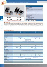
High Speed Local I/O Modules: Parallel Bus<br />
I-8K High Profile Modules: More at www.icpdas.com > Products > PAC - 8K & 87K I/O Modules<br />
I-8K Analog I/O Modules<br />
I-8014W<br />
I-8017HW<br />
I-8024W<br />
16-bit 250K sampling rate 8/16-ch. analog input module (The scan rate cannot<br />
reach 250K when using in the ISaGRAF PAC)<br />
8-ch. Differential or 16-ch. Single-ended, 14-bit, High Speed Analog Input<br />
Module. (current input require external 125 resistor) (The scan rate cannot<br />
reach 100K when using in the ISaGRAF PAC)<br />
4-ch. Isolated Analog Output Module (+/-10 V, 0 ~ +20 mA)<br />
I-8K Digital I/O Modules<br />
I-8037W<br />
I-8040W<br />
I-8040PW<br />
I-8041W<br />
I-8041AW<br />
I-8042W<br />
I-8046W<br />
I-8050W<br />
I-8051W<br />
I-8052W<br />
I-8053W<br />
I-8053PW<br />
I-8054W<br />
I-8055W<br />
I-8056W<br />
I-8057W<br />
I-8058W<br />
I-8060W<br />
I-8063W<br />
I-8064W<br />
I-8068W<br />
I-8069W<br />
16-ch. Isolated Open Collector Output Module<br />
32-ch. Isolated Digital Input Module<br />
32-ch. Isolated Digital Input with Low Pass Filter Module<br />
32-ch. Isolated Open Collector Digital Output Module (Sink)<br />
32-ch. Isolated Open Collector Digital Output Module (Source)<br />
16-ch. Isolated Digital Input & 16-ch. Isolated Open Collector Digital Output<br />
Module<br />
16-ch. Isolated Digital Input Module<br />
16-ch. Universal Digital I/O Module<br />
16-ch. Non-isolated Digital Input Module<br />
8-ch. Differential Isolated Digital Input Module<br />
16-ch. Isolated Digital Input Module<br />
16-ch. Isolated Digital Input with Low Pass Filter Module<br />
8-ch. Isolated Digital Input Module & 8-ch. Isolated Open Collector Digital Output<br />
Module<br />
Non-isolated 8-ch. Digital Logic Input Module & 8-ch. Open Collector Digital<br />
Output Module<br />
16-ch. Non-isolated Open Collector Output Module<br />
16-ch. Isolated Open Collector Output Module<br />
8-ch. Differential Isolated Digital Input Module, Max. AC/DC Input : 250V<br />
6-ch. Relay Output Module, AC: 0.6 A @ 125 V , 0.3 A @ 250 V; DC: 2 A @ 30 V<br />
4-ch. Differential Isolated digital input & 4-ch. Relay output module, AC : 0.6 A @<br />
125 V ; 0.3 A @ 250 V<br />
8-ch. Power Relay Output Module, AC: 5 A @ 250 V, DC: 5 A @ 30 V<br />
4-ch. Form-A, 5 A @ 250 V AC /28 V DC & 4-ch. Form-C, 5 A (NO) /3 A (NC) @ 277<br />
V AC /30 V DC Relay Output Module<br />
8-ch. PhotoMOS Relay Output Module, Max. AC/DC: 1 A @ 60 V<br />
I-8K Counter/Frequency Modules<br />
I-8084W<br />
I-8088W<br />
4-ch. Encoder, can be dir/pulse, or up/down or A/B phase (Quad. mode), Not<br />
support Encoder Z-index<br />
8-ch. PWM Output and 8-ch. isolated DI Module, software support 1 Hz ~ 100<br />
kHz (non-continuous).<br />
I-8K Motion Modules<br />
8 Getting Started : The XPAC-8xx7-CE6 PAC, Ver.1.23 , May 2012 by ICP DAS
I-8093W<br />
3-axis Encoder Module, max. 1M Hz for quadrant input mode, max. 4M Hz for<br />
pulse/direction and cw/ccw input model<br />
I-8090W 3-axis Encoder Module<br />
I-8091W 2-axis Stepping/Servo Motor Control Card without encoder input<br />
I-8092F<br />
High Speed 2-axis Motion Control Module, with FRnet Master (For XP-8xx7-CE6<br />
only)<br />
I-8094 High Speed 4-axis Motion Control Module (For XP-8xx7-CE6 only)<br />
I-8094F<br />
High Speed 4-axis Motion Control Module, with FRnet Master (For XP-8xx7-CE6<br />
only)<br />
I-8K Communication Modules<br />
I-8112iW<br />
I-8114W<br />
I-8114iW<br />
I-8142iW<br />
I-8144iW<br />
I-8172W<br />
I-8K CAN Bus Modules<br />
I-8123W<br />
2-ch. Isolated RS-232 Expansion Module<br />
4-ch. non-isolated RS-232 Expansion Module<br />
4-ch. Isolated RS-232 Expansion Module<br />
2-ch. Isolated RS-422/485 Expansion Module<br />
4-ch. Isolated RS-422/485 Expansion Module<br />
2-port FRnet Module<br />
1 Port High Performance CANopen Master Module<br />
RS-485 Remote I/O Modules: Serial Interface; HOT-SWAP<br />
I-87K High Profile Modules: More at www.icpdas.com > Products > PAC - 8K & 87K I/O Modules<br />
I-87K Analog I/O Modules<br />
I-87005W<br />
I-87013W<br />
I-87015W<br />
I-87015PW<br />
I-87017RW<br />
I-87017RCW<br />
I-87017W<br />
I-87017W-A5<br />
I-87017DW<br />
I-87017ZW<br />
I-87018PW<br />
I-87018RW<br />
I-87018W<br />
I-87018ZW<br />
I-87019PW<br />
I-87019RW<br />
8-ch. Thermistor input and 8-ch. digital output module<br />
4-ch., 16-bit, 10 Hz (Total), 2/3/4 Wire RTD Input Module with Open Wire<br />
Detection<br />
7-ch., 16-bit, 12 Hz (Total), RTD Input Module with Open Wire Detection (for<br />
short sensor distance)<br />
7-ch. RTD Input Module with 3-wire RTD lead resistance elimination and with<br />
Open Wire Detection (for long sensor distance)<br />
8-ch. Differential , 16/12-bit, 10/60 Hz (Total) Analog Input Module with 240 V rms<br />
Over Voltage Protection, Range of -20 ~ +20 mA Requires Optional External<br />
125 Ω Resistor<br />
8-ch. Differential , 16/12-bit, 10/60 Hz(Total) Current Input Module<br />
8-ch. Analog Input Module<br />
8-ch. High Voltage Input Module<br />
8-ch. Analog Input Module (Gray Cover) (RoHS)<br />
10/20-ch. Analog Input Module with High Voltage Protection (RoHS)<br />
8-ch. Thermocouple Input Module (Gray Cover) (RoHS)<br />
8-ch. Thermocouple Input Module. Recommend to use the better I-87018Z.<br />
8-ch. Thermocouple Input Module. Recommend to use the better I-87018Z.<br />
10-ch. Differential , 16-bit, 10 Hz (Total), Thermocouple Input Module with 240<br />
V rms Over Voltage Protection, Open Wire Detection, Range of +/-20 mA, 0~20<br />
mA, 4~20 mA requires Optional External 125 Ω Resistor<br />
8-ch. Universal Analog Input Module (RoHS) (With a CN-1824 Daughter Board)<br />
8-ch. Diff. , 16-bit, 8 Hz (Total), Universal Analog Input Module with 240 V rms<br />
Over Voltage Protection, Open Wire Detection (V, mA, Thermocouple; Range<br />
Getting Started : The XPAC-8xx7-CE6 PAC, Ver.1.23 , May 2012 by ICP DAS 9
I-87019ZW<br />
I-87024CW<br />
I-87024DW<br />
I-87024RW<br />
I-87024W<br />
I-87028CW<br />
I-87H17W<br />
of -20 ~ +20 mA need to set Jumper on board)<br />
10-ch. Universal Analog Input Module (Gray Cover) (RoHS), Includes the<br />
I-87019ZW Module and a DB-1820 Daughter Board<br />
4-ch. 12-bit channel to channel isolated current output module with open-wire<br />
detection<br />
4-ch. 14-bit analog output module<br />
4-ch. 14-bit analog output module<br />
4-ch. 14-bit analog output module (0 ~ +5 V, +/-5 V, 0 ~ +10 V, +/-10 V, 0 ~ +20<br />
mA, +4 ~ +20 mA)<br />
8-ch. 12-bit current output module<br />
8-ch. analog input module and HART master module.<br />
I-87K Multifunction I/O Modules<br />
I-87026PW<br />
I-87K Digital I/O Modules<br />
6-ch. Analog Input, 2-ch. Analog Output, 2-ch. Digital Input and 2-ch. Digital<br />
Output Module (RoHS)<br />
I-87037W 16-ch. source type Isolated Digital Output Module(RoHS)<br />
I-87040W 32-ch. Isolated Digital Input Module<br />
I-87040PW 32-ch. Isolated Digital Input Module with 16-bit Counters (RoHS)<br />
I-87041W 32-ch. Sink Type Open Collector Isolated Digital Output Module<br />
I-87046W 16-ch. Non-Isolated Digital Input Module for Long Distance Measurement<br />
I-87051W 16-ch. Non-Isolated Digital Input Module<br />
I-87052W 8-ch. Differential , Isolated Digital Input Module<br />
I-87053PW 16-ch. Isolated Digital Input Module with 16-bit Counters<br />
I-87053W 16-ch. Isolated Digital Input Module<br />
I-87053W-A5 16-ch. 68 ~ 150 V DC Isolated Digital Input Module<br />
I-87053W-AC1 16-ch. AC Isolated Digital Input Module with 16-bit Counters<br />
I-87053W-E5 16-channel 68-150 V DC solated Digital Input Module with 16-bit Counters<br />
I-87054W Isolated 8-ch. DI and 8-ch. Open Collector DO Module<br />
I-87055W Non-Isolated 8-ch. DI and 8-ch. Open Collector DO Module<br />
I-87057W 16-ch. Open Collector Isolated Digital Output Module<br />
I-87057PW 16-ch. Open Collector Isolated Digital Output Module<br />
I-87058W 8-ch. 80~250 V AC Isolated Digital Input Module<br />
I-87059W 8-ch. Differential 10-80 VAC Isolated Digital Input Module<br />
I-87061W 16-ch. Relay Output Module (RoHS)<br />
I-87063W<br />
4-ch. Differential Isolated Digital Input and 4-ch. Relay Output Module 5 A (NO)<br />
/ 3 A(NC) @ 5 ~ 24 V DC ; 5 A(NO) / 3 A(NC) @ 0 ~ 250 V AC<br />
I-87064W 8-ch. Relay Output Module, 5 A (47~63 Hz) @ 0~ 250 V AC ; 5 A @ 0~ 30 V DC<br />
I-87065W 8-ch. AC SSR Output Module, AC: 1.0 A rms @ 24 ~ 265 V rms<br />
I-87066W 8-ch. DC SSR Output Module , DC: 1.0 A rms @ 3 ~ 30 V DC<br />
4-ch. Form-A Relay Output and 4-ch. Form-C Relay Output Module ; Form-A: 8<br />
I-87068W A @ 250 V AC ; 8 A @ 28 V DC; Form-C: 5 A (NO) / 3 A (NC) @ 277 V AC ; 5 A(NO )<br />
/ 3 A(NC) @ 30 V AC<br />
I-87069W 8-ch. PhotoMOS Relay Output Module, Max. AC/DC: 0.13 A @ 350 V<br />
I-87K Counter/Frequency Modules<br />
I-87082W<br />
I-87K PWMS Modules<br />
I-87088W<br />
2-ch. Counter/Frequency Module, Isolated or Non-isolated Inputs<br />
8-ch. PWM outputs, software support 1 Hz~100 kHz, (non-continuous), duty:<br />
10 Getting Started : The XPAC-8xx7-CE6 PAC, Ver.1.23 , May 2012 by ICP DAS
I-87K GPS Modules<br />
I-87211W<br />
0.1 ~ 99.9%<br />
Time-Synchronization and GPS module for getting UTC/local time and local<br />
Longitude/Latitude<br />
RS-485 Remote I/O Modules<br />
I-7000<br />
DCON Protocol<br />
M-7000<br />
Modbus RTU and<br />
DCON Protocol<br />
tM-7000<br />
DCON, Modbus RTU,<br />
Modbus ASCII<br />
Protocol<br />
www.icpdas.com.tw > Product > Solutions > Remote I/O Modules/Units ><br />
RS-485 Remote I/O Modules > I-7000 Modules<br />
www.icpdas.com.tw > Product > Solutions > Remote I/O Modules/Units ><br />
RS-485 Remote I/O Modules > M-7000 Modules<br />
www.icpdas.com.tw > Product > Solutions > Remote I/O Modules/Units ><br />
RS-485 Remote I/O Modules > tM Series Module<br />
RS-485 Remote I/O Expansion Unit<br />
RU-87P1/2/4/8<br />
www.icpdas.com.tw > Product > Solutions > Remote I/O Modules/Units ><br />
Hot-Swap,<br />
Remote I/O Expansion Unit > RS-485 Bus<br />
Auto-Config.<br />
I-87K1/4/5/8/9 www.icpdas.com.tw > Product > Solutions > Remote I/O Modules/Units ><br />
Remote I/O Expansion Unit > RS-485 Bus<br />
Ethernet I/O Modules<br />
ET-7000<br />
Web based<br />
PET-7000<br />
PoE Web based<br />
tPET/tET-7000<br />
Modbus TCP based<br />
(PoE)<br />
Ethernet I/O Expansion Unit<br />
I-8KE4/8-MTCP<br />
Modbus/TCP based<br />
www.icpdas.com.tw > Product > Solutions > Remote I/O Modules/Units ><br />
Ethernet I/O > ET-7000<br />
www.icpdas.com.tw > Product > Solutions > Remote I/O Modules/Units ><br />
Ethernet I/O > PET-7000<br />
www.icpdas.com.tw > Product > Solutions > Remote I/O Modules/Units ><br />
Ethernet I/O > PETL-7000 & tPET/tET<br />
www.icpdas.com.tw > Product > Solutions > Remote I/O Modules/Units ><br />
Ethernet I/O > I-8KE4/8-MTCP<br />
Getting Started : The XPAC-8xx7-CE6 PAC, Ver.1.23 , May 2012 by ICP DAS 11
Performance Comparison Table of ISaGRAF PACs<br />
Please click on the link ISaGRAF Comparison Table or follow the below steps:<br />
1. www.icpdas.com<br />
2. Click here to go to the ISaGRAF page<br />
3. Comparison Table<br />
12 Getting Started : The XPAC-8xx7-CE6 PAC, Ver.1.23 , May 2012 by ICP DAS
Specifications: XP-8047-CE6/ 8347-CE6/ 8747-CE6<br />
PAC Specifications:<br />
Models XP-8047-CE6 XP-8347-CE6 XP-8747-CE6<br />
System Software<br />
OS<br />
.Net Compact<br />
Framework<br />
Windows CE 6.0 R3 Core<br />
3.5<br />
Embedded Service FTP Server, ASP (Java Script, VB Script), SQL Compact Edition 3.5<br />
SDK Provided Dll for Visual Studio .Net 2005/2008<br />
Multilanguage<br />
Support<br />
English, German, French, Spanish, Russian, Italian, Japanese, Simplified Chinese,<br />
Traditional Chinese<br />
Development Software<br />
ISaGRAF<br />
Software<br />
ISaGRAF<br />
Ver.3<br />
Languages<br />
Max. Code<br />
Size<br />
Scan Time<br />
IEC 61131-3 standard.<br />
LD, ST, FBD, SFC, IL & FC<br />
Support Soft-GRAF HMI: XP-8xx7-CE6, WP-8xx7, VP-2xW7 and WP-5xx7 PAC<br />
2 MB<br />
3 ~ 15 ms for normal program<br />
15 ~ 50 ms (or more) for complex or large program<br />
Non-ISaGRAF<br />
Options: VS.NET 2005/2008 (VB.NET, C#.NET)<br />
Web Service<br />
Web HMI<br />
Security<br />
CPU Module<br />
CPU<br />
System Memory<br />
Dual Battery Backup<br />
SRAM<br />
Flash<br />
EEPROM<br />
CF Card<br />
RTC (Real Time<br />
Clock)<br />
64-bit Hardware<br />
Serial Number<br />
Dual Watchdog<br />
Timers<br />
PC running Internet Explorer can monitor/control PAC via Internet/modem<br />
Web HMI supports three levels username and password protection. (high/middle/low)<br />
LX800, 500 MHz<br />
512 MB DDR SDRAM<br />
512 KB; data valid up to 5 years (for retain variables)<br />
4 GB as IDE Master<br />
16 KB<br />
2 GB (support up to 32 GB)<br />
Provide second, minute, hour, date, day of week, month, year<br />
Yes, for Software Copy Protection<br />
Yes<br />
Rotary Switch Yes (0 ~ 9)<br />
Getting Started : The XPAC-8xx7-CE6 PAC, Ver.1.23 , May 2012 by ICP DAS 13
Models XP-8047-CE6 XP-8347-CE6 XP-8747-CE6<br />
DIP Switch - Yes (8 bits)<br />
VGA & Communication Ports<br />
VGA Yes, (resolution: 1024 x 768, 800 x 600, 640 x480)<br />
Ethernet<br />
RJ-45 x 2, 10/100 Base-TX (Auto-negotiating, Auto MDI/MDI-X, LED indicators).<br />
USB 2.0 2<br />
COM 1<br />
RS-232 (RxD,<br />
TxD and GND);<br />
non-isolated<br />
Internal communication with the high profile I-87K series<br />
modules in slots<br />
COM 2<br />
COM 3<br />
COM 4<br />
COM 5<br />
I/O Expansion Slots<br />
Slot Number<br />
RS-232 (RxD, TxD and GND); non-isolated<br />
RS-485 (Data+, Data-) with internal self-tuner ASIC; 3000 VDC isolated<br />
RS-232/RS-485 (RxD, TxD, CTS, RTS and GND for RS-232, Data+ and Data- for<br />
RS-485); non-isolated<br />
RS-232 (RxD, TxD, CTS, RTS, DSR, DTR, CD, RI and GND); non-isolated<br />
0 3 7<br />
Note: For High Profile I-8K and I-87K Modules Only<br />
Mechanical<br />
Dimensions<br />
(W x L x H)<br />
Installation<br />
137 x 132 x 125 mm 231 x 132 x 125 mm 355 x 132 x 125 mm<br />
DIN-Rail or Wall Mounting<br />
Environmental<br />
Operating<br />
Temperature<br />
Storage<br />
Temperature<br />
Ambient Relative<br />
Humidity<br />
-25 ~ +75°C<br />
-30 ~ +80°C<br />
10 ~ 90% RH (non-condensing)<br />
Power<br />
Input Range<br />
Isolation<br />
Redundant Power<br />
Inputs<br />
+10 ~ +30 VDC<br />
1 kV<br />
Yes, with one power relay (1 A @ 24 VDC) for alarm<br />
Capacity 15 W 35 W 35 W<br />
Consumption 14.4 W 14.4 W 16.8 W<br />
XP-8xx7-CE6 ISaGRAF Specifications:<br />
Models XP-8047-CE6 XP-8347-CE6 XP-8747-CE6<br />
Protocols (some protocols need optional devices)<br />
14 Getting Started : The XPAC-8xx7-CE6 PAC, Ver.1.23 , May 2012 by ICP DAS
Models XP-8047-CE6 XP-8347-CE6 XP-8747-CE6<br />
Net ID<br />
Modbus TCP/IP Master<br />
Modbus RTU/ASCII<br />
Master<br />
Modbus RTU Slave<br />
Modbus TCP/IP Slave<br />
Web HMI Protocol<br />
User-Defined Protocol<br />
I-7000 & I-87K RS-485<br />
Remote I/O<br />
M-7000 Series Modbus<br />
I/O<br />
Modbus TCP/IP I/O<br />
FRnet I/O<br />
Send Email<br />
Ebus<br />
SMS: Short Message<br />
Service<br />
MMICON/LCD<br />
UDP Server & UDP<br />
Client : Exchange<br />
Message & Auto-Report<br />
TCP Client :<br />
Exchange Message &<br />
Auto-Report<br />
1 ~ 255, user-assigned by software<br />
Link to max. 100 devices that support Standard Modbus TCP/IP Slave protocol<br />
(FAQ-113)<br />
Max. 33 Ports : COM1 ~ 33 (To connect to other Modbus Slave devices). (*)<br />
Max. 9 Ports : COM1 ~ 33 (For connecting ISaGRAF, PC/HMI/OPC Server & HMI<br />
panels). (*)<br />
2 Ethernet Ports all support Modbus TCP/IP Slave protocol for connecting<br />
ISaGRAF & PC/HMI. 2 Ports support up to 64 connections. Note: If PAC uses 1<br />
connection to connect each PC/HMI, it can connect up to 64 PC/HMI; If PAC uses<br />
2 connections to connect each PC/HMI, it can connect up to 32 PC/HMI; When<br />
one Ethernet port is broken, the other one can still connect to PC/HMI.<br />
Ethernet Ports for connecting PC running Internet Explorer.<br />
User can write his own protocol applied at COM1~COM5 & COM6~COM33 by<br />
Serial communication function blocks. (*)<br />
One of COM3~4 supports I-7000 I/O modules, I-87K base + I-87K Serial I/O<br />
boards or RU-87Pn + I-87K High Profile I/O boards as remote I/O. Max. 255<br />
modules of I-7000/87K Remote I/O for one PAC.<br />
Max. 33 RS-485 ports. Each port can connect up to 32 M-7000 Modules. (*)<br />
LAN2 supports ICP DAS Ethernet I/O : I-8KE4-MTCP and I-8KE8-MTCP. If LAN2 is<br />
broken, it will switch to LAN1 automatically to continuously work. (This need LAN1<br />
& LAN2’s IP are set in the same IP domain) (FAQ-042)<br />
Support max 7 pcs. I-8172W boards in slot 1 ~ 7 to connect to FRnet I/O modules,<br />
like FR-2053, FR-2057 FR-32R, FR-32P. (FAQ-048). Each I-8172W board can link<br />
max. 256 DI plus 256 DO ch.<br />
Support functions to send Email with one attached file via Ethernet port.<br />
To exchange data between ICP DAS’s ISaGRAF Ethernet PACs via Ethernet port.<br />
(LAN2 Port only)<br />
COM4 or COM5 can link to a GSM Modem to support SMS. User can request<br />
data/control the controller by cellular phone. The controller can also send data &<br />
alarms to user’s cellular phone.<br />
Optional GSM Modem: GTM-201-RS232 (850/900/1800/1900 GSM/GPRS External<br />
Modem)<br />
COM4 or COM5 supports ICP DAS’s MMICON.<br />
LAN1 or LAN2 support UDP Server and UDP Client protocol to send/receive<br />
message to / from PC/HMI or other devices. For example, to automatically report<br />
data to InduSoft’s RXTX driver.<br />
LAN1 or LAN2 support TCP Client protocol to send / receive message to / from<br />
PC/HMI or other devices which support TCP server protocol.<br />
Getting Started : The XPAC-8xx7-CE6 PAC, Ver.1.23 , May 2012 by ICP DAS 15
Models XP-8047-CE6 XP-8347-CE6 XP-8747-CE6<br />
GPRS/SMS<br />
SQL Client<br />
Hot-Swap and<br />
Redundant System<br />
CAN/CANopen<br />
CANopen Master<br />
HART Solutions<br />
FTP Client<br />
Soft-GRAF HMI<br />
Support the I-8212W (2G/3G) card to receive/send a short message or to dial up<br />
to link the Internet by GPRS connection to send an email or communicate with<br />
remote stations by using "Ftp Client" (FAQ-151) and "TCP Client" / "UDP Server"<br />
/ "UDP Client" (FAQ-143).<br />
Support SQL Client function to write data to (or read data from) Microsoft SQL<br />
Server (2000 SP3, 2005, 2008).<br />
This redundant system has setup two “Active IP” address point to the active LAN1<br />
and LAN2 ports always. One or more PC/HMI/SCADA can communicate with this<br />
redundant system via one of the two given active IP. So the PC/HMI/SCADA can<br />
access to the system easily without any notice about which PAC is currently<br />
active. Moreover, the new redundant system can integrate with the<br />
RU-87P4/87P8 Expansion Unit plus the I-87K high-profile I/O cards to support the<br />
hot-swap application. If the I/O card is damaged, the maintenance person just<br />
takes one good-card with same model number to hot-swap the damaged one<br />
without stopping this redundant system. (FAQ-138 and FAQ-125)<br />
COM1, 2, 4, 5 or COM6~COM33 to connect one I-7530 (converter: RS-232 to<br />
CAN) to support CAN/CANopen devices and sensors. One PAC supports max.32<br />
RS-232 ports to connect max.32 I-7530. (*) (FAQ-086)<br />
Support the I-8123W CANopen Master card to connect other CANopen slave<br />
devices. (FAQ-145)<br />
Support I-87H17W modules in slot 1 to 7 to communicate with other HART<br />
devices.<br />
Support FTP client to upload files in the PAC to a remote FTP server on PC.<br />
(FAQ-151)<br />
Support the Soft-GRAF HMI . User can use the Soft-GRAF Studio on the PC to<br />
design the HMI screen and then download it to the PAC to display the HMI on the<br />
PAC. (FAQ-146)<br />
Optional I/O Functions (Refer to ISaGRAF PAC I/O Selection Guide for I/O Module list)<br />
PWM<br />
Output<br />
Counter<br />
Encoder<br />
Frequency<br />
High Speed<br />
PWM Module<br />
DO Module<br />
as PWM<br />
Parallel DI<br />
Counter<br />
Serial DI<br />
Counter<br />
I-7088, I-8088W, I-87088W: 8-ch PWM outputs, software support 1 Hz ~ 100 kHz<br />
(non-continuous), duty: 0.1 ~ 99.9%<br />
88-ch max. 250 Hz max. For Off=2 & On=2 ms. Output square wave: Off:<br />
2~32766 ms, On: 2 ~ 32766 ms.<br />
Optional DO Boards: I-8037W, 8041W, 8041AW, 8042W, 8050W, 8054W,<br />
8055W, 8056W, 8057W, 8060W, 8063W, 8064W, 8068W, 8069W. (Relay Output<br />
boards cannot generate fast square wave)<br />
8 ch. max. for 1 controller. Counter val: 32 bit. 250 Hz max. Min. ON & OFF width<br />
must >2 ms.<br />
Optional DI boards: I-8040W, 8040PW, 8042W, 8046W, 8048W, 8050W, 8051W,<br />
8052W, 8053W, 8053PW, 8054W, 8055W, 8058W, 8063W.<br />
Counter input: 100 Hz max. Counter value: 0 ~ 65535 (16 bit)<br />
Optional serial I-87K DI boards: I-87040W, 87046W, 87051W, 87052W, 87053W,<br />
87053W-A5, 87054W, 87055W, 87058W, 87059W, 87063W.<br />
16 Getting Started : The XPAC-8xx7-CE6 PAC, Ver.1.23 , May 2012 by ICP DAS
Models XP-8047-CE6 XP-8347-CE6 XP-8747-CE6<br />
Motion<br />
Remote DI<br />
Counter<br />
High Speed<br />
Counter<br />
Encoder<br />
Frequency<br />
Motion<br />
Control<br />
All remote I-7K/I-87K DI modules support counters. 100 Hz max. value: 0 ~ 65535<br />
I-87082W: 100 kHz max., 32-bit; I-8084W: 250 kHz max., 32-bit<br />
I-8093W: 3-axis Encoder Module, max. 1M Hz for quadrant input mode, max. 4<br />
MHz for pulse/direction and cw/ccw input mode. (FAQ-112)<br />
I-8084W: 250 kHz max., 4-ch encoder, pulse/direction or up/down or A/B phase<br />
(Quad. mode). Not support Encoder Z-index. (FAQ-100)<br />
I-87082W: 2-ch, 1 Hz ~ 100 kHz;<br />
I-87088W: 8-ch, 0.1 Hz ~ 500 kHz;<br />
I-8084W: 8-ch, 1 Hz ~ 250 kHz;<br />
XP-8347-CE6 / XP-8747-CE6 : Integrate with one or several I-8092F (2-axis) or<br />
I-8094F/I-8094 (4-axis)<br />
* Note: COM6 ~ COM33 are resided at the expansion boards if they are plugged on slot 1~7 of<br />
XP-8xx7-CE6. XP-8347-CE6/8747-CE6’s COM1 is for internal communication with I-87K<br />
modules in slots only.<br />
* ISaGRAF FAQ: http://www.icpdas.com/faq/isagraf.htm<br />
* Recommend to use NS-205/NS-208 Industrial Ethernet Switch.<br />
Getting Started : The XPAC-8xx7-CE6 PAC, Ver.1.23 , May 2012 by ICP DAS 17
Chapter 1<br />
Typical Application<br />
The website for the applications supporting list of all ISaGRAF PACs :<br />
http://www.icpdas.com/products/PAC/common_file/application-notes.htm<br />
1.1 Motion Control : Using I-8094F/8092F/8094<br />
• XP-8xx7-CE6 plus I-8094F/8092F/8094 motion modules with daughter<br />
boards<br />
• ISaGRAF + Soft-GRAF: User can achieve motion control, HMI design and<br />
I/O control within the ISaGRAF software.<br />
• I-8094 is a 4-axis high speed motion control module.<br />
• I-8094F (4-axis) and I-8092F (2-axis) are high speed motion control<br />
modules with FRnet master.<br />
• More at www.icpdas.com> FAQ > Software > ISaGRAF Ver.3 (English) –<br />
FAQ-132.<br />
Getting Started : The XPAC-8xx7-CE6 PAC, Ver.1.23 , May 2012 by ICP DAS 2-1
1.2 Soft-GRAF HMI : Create A Colorful HMI<br />
• Soft-GRAF Studio<br />
‣ Simplify HMI screen editing (Mouse drag and drop)<br />
‣ HMI without writing programming language<br />
• Support various and colorful HMI objects:<br />
‣ Page (Max. 200, support password security)<br />
‣ Numeric (Input, input security, display)<br />
‣ Text (Dynamic/static text display)<br />
‣ Picture (Animated/static picture display)<br />
‣ Moving Trace (1-axis or 2-axis)<br />
‣ Bar-meter (Vertical/horizontal dynamic display)<br />
‣ Button displayed as text<br />
‣ Button displayed as picture<br />
‣ Built-in various objects<br />
• Multi-language: English, Traditional Chinese,Simplify Chinese, Russian…<br />
• HMI behave smoothly<br />
• More at: Chapter 2.5 & FAQ www.icpdas.com > FAQ > Software > ISaGRAF<br />
Ver.3 – FAQ-146<br />
Running HMI and Control Logic in the Same PAC<br />
2-2 Getting Started : The XPAC-8xx7-CE6 PAC, Ver.1.23 , May 2012 by ICP DAS
1.3 eLogger HMI Application<br />
• ICP DAS eLogger is an easy and useful HMI development tool which helps<br />
user to create user-friendly pictures and control items.<br />
• More at: www.icpdas.com > FAQ > Software > ISaGRAF > FAQ-115.<br />
Getting Started : The XPAC-8xx7-CE6 PAC, Ver.1.23 , May 2012 by ICP DAS 2-3
1.4 Connect the Smart Power Meter PM-2133/2134<br />
• ISaGRAF PAC support standard Modbus protocol, support multiple<br />
RS-485 ports to connect to multiple PM-213x Smart meters.<br />
• For the power measurement control systems in small/medium sized stores,<br />
buildings and factories with electric equipments.<br />
• PM-213x smart meter with "Wh" pulse output is useful in the systems<br />
needing to connect the meter tester.<br />
• PM-213x smart meter with wired clip-on CT is easily wiring for on-line<br />
installation, suitable for the uninterruptible power systems.<br />
• PM-213x is a series of 3 Phase/4 Loops 1 Phase Compact Smart Meter<br />
with true RMS energy and power parameters measurement in compact<br />
size. The ISaGRAF PACs combining with PM-213x can apply to various<br />
control/monitor systems about intelligent electric power measurement.<br />
• More at www.icpdas.com> FAQ > Software > ISaGRAF Ver.3 (English) -<br />
129.<br />
2-4 Getting Started : The XPAC-8xx7-CE6 PAC, Ver.1.23 , May 2012 by ICP DAS
1.5 Redundant Communication System<br />
• Please refer to www.icpdas.com > FAQ > Software > ISaGRAF ><br />
FAQ-119 for more information about RS-485 and Ethernet redundant<br />
communication mechanism and applications.<br />
1.6 Redundant System - Ethernet I/O<br />
• If one Ethernet cable is broken or damaged, the other one will still handle the<br />
Ethernet I/O and exchange data with the other redundant controller.<br />
• The scan of Ethernet I/O is much faster than that of RS-485 I-7000/I-87K I/O.<br />
• More at www.icpdas.com > FAQ > Software > ISaGRAF Ver.3 (English) -<br />
125<br />
Getting Started : The XPAC-8xx7-CE6 PAC, Ver.1.23 , May 2012 by ICP DAS 2-5
1.7 Redundant System – Hot-Swap RS-485 I/O<br />
• If one Ethernet cable of PAC is broken or damaged, the other one will still<br />
work. If one controller is dead, the other one will take over the control of the<br />
RS-485 I/O.<br />
• PC/HMI can connect to this redundant system by one or two active IP.<br />
• More at www.icpdas.com > FAQ > Software > ISaGRAF Ver.3 - 093<br />
1.8 Redundant System – with iDCS-8000<br />
• Dual PACs, dual Ethernet ports redundant system<br />
• PC/HMI can just connect one IP address to link to the redundant system. If<br />
the active PAC is damaged, it will take about 0.5 seconds to switch to the<br />
other PAC.<br />
• More at www.icpdas.com > FAQ > Software > ISaGRAF Ver.3 – 125<br />
2-6 Getting Started : The XPAC-8xx7-CE6 PAC, Ver.1.23 , May 2012 by ICP DAS
1.9 Modbus Master: TCP/IP<br />
• Each XP-8xx7-CE6, WP-8xx7 or VP-25W7/23W7 supports to link to max.<br />
100 Modbus TCP/IP slave devices.<br />
• Support various Standard Modbus TCP/IP Slave devices.<br />
• More at: www.icpdas.com > FAQ > Software > ISaGRAF Ver.3 (English) ><br />
113<br />
1.10 Modbus Master: RTU, ASCII, RS-232/485/422<br />
• Support up to 33 ports:<br />
COM1~COM5 (only XP-8047-CE6 can use COM1 as Modbus Master)<br />
COM6~COM33 (if I-8112iW/ 14W/ 14iW/ 42iW/ 44iW in Slot1~7)<br />
• Note: XP-8347-CE6 / 8747-CE6‟s COM1 is for internal communication<br />
with I-87K modules in slots only.<br />
• Can link to Modbus PLC or M-7000 I/O or Modbus devices<br />
(Power meter, temperature controller, inverter etc.)<br />
Getting Started : The XPAC-8xx7-CE6 PAC, Ver.1.23 , May 2012 by ICP DAS 2-7
1.11 Modbus Slave: RTU/TCP<br />
• Modbus RTU Slave (RS-232/485/422): max. 9 ports<br />
• Modbus TCP/IP Slave : max. 64 connections<br />
1.12 Communicate With Other TCP/IP Server or UDP<br />
Client/Server Devices<br />
2-8 Getting Started : The XPAC-8xx7-CE6 PAC, Ver.1.23 , May 2012 by ICP DAS
1.13 Multiple Web HMI – Monitor & Control Everywhere!<br />
1.14 Send Email With or Without One Attached File<br />
• More at www.icpdas.com > FAQ > Software > ISaGRAF Ver.3 (English) -<br />
067<br />
Getting Started : The XPAC-8xx7-CE6 PAC, Ver.1.23 , May 2012 by ICP DAS 2-9
1.15 Data-Recorder & Data-Logger<br />
PC can load the data file stored in the<br />
XP-8xx7-CE6’s Flash Disk or CF card<br />
by ftp or by Web HMI.<br />
1.16 Remote I/O Application<br />
2-10 Getting Started : The XPAC-8xx7-CE6 PAC, Ver.1.23 , May 2012 by ICP DAS
1.17 SMS: Short Message Service<br />
• Short message can be sent in multiple language format (like Chinese,<br />
English... others)<br />
• More at www.icpdas.com > FAQ > Software > ISaGRAF Ver.3 (English) -<br />
111<br />
1.18 Auto-report Acquisition & Control Data<br />
• XP-8xx7-CE6 can use UDP IP Client to auto-report acquisition data &<br />
control data to local or remote internet PC/Server.<br />
• Advantage: Every PAC in the different location doesn‟t need a fixed<br />
Internet IP<br />
• More at www.icpdas.com > FAQ > Software > ISaGRAF Ver.3 (English) -<br />
065<br />
Getting Started : The XPAC-8xx7-CE6 PAC, Ver.1.23 , May 2012 by ICP DAS 2-11
1.19 Stress Monitoring Application of Constructions<br />
• ICP DAS releases effective "VW Sensor" (Vibration Wire solution) and<br />
"Carlson Strain Gauge Inputs" solution . It's useful for measuring the stress<br />
of constructions like building, bridge, dam, etc.<br />
• Each ISaGRAF PAC (as FAQ-091) supports the I-87089 (the VW master<br />
card) plus the DN-1618UB (daughter board) to achieve the "VW Sensor"<br />
application.<br />
• Each XP-8xx7-CE6, WP-8xx7 or VP-25W7/23W7 supports the I-87113DW<br />
module (the master card of Carlson Strain Gauge Inputs) plus the<br />
DN-1619 (DN-1618U-Test1) (daughter board) to achieve the "Carlson<br />
Strain Gauge Inputs" application.<br />
• Please click www.icpdas.com > FAQ > Software > ISaGRAF Ver.3<br />
(English) - 091, 128 for more information.<br />
2-12 Getting Started : The XPAC-8xx7-CE6 PAC, Ver.1.23 , May 2012 by ICP DAS
1.20 Fast FRnet Remote I/O<br />
• Advantage of FRnet I/O: Fast I/O scan: About 3 ms/scan. (It depends on<br />
your program‟s PLC scan time. Ex: If the ISaGRAF program‟s PLC scan<br />
time is about 9 ms, then the scan time for all will be 9 ms, not 3 ms)<br />
• Note: Doesn‟t support FRnet AI/AO I/O modules yet.<br />
• www.icpdas.com > FAQ > Software > ISaGRAF Ver.3 (English) - 082<br />
1.21 Integrate with CAN/CANopen Devices & Sensors<br />
• XP-8xx7-CE6 supports max. 32 I-7530 (RS-232 to CAN Converter)<br />
• www.icpdas.com > FAQ > Software > ISaGRAF Ver.3 (English) > 086<br />
Getting Started : The XPAC-8xx7-CE6 PAC, Ver.1.23 , May 2012 by ICP DAS 2-13
1.22 ZigBee Wireless Solution<br />
The XP-8xx7-CE6 plus ZB-2550P and ZB-2551P RS-232/RS-485 Converters<br />
can apply wireless communication, reduce the wiring cost, and achieve the<br />
mission of remote I/O control and data acquisition.<br />
Please refer to www.icpdas.com > FAQ > Software > ISaGRAF Ver.3 (English)<br />
> 110<br />
2-14 Getting Started : The XPAC-8xx7-CE6 PAC, Ver.1.23 , May 2012 by ICP DAS
1.23 GPS Application: with I-87211W & GPS-721<br />
• XP-8xx7-CE6, WP-8xx7, VP-2xW7, iP-8xx7, μPAC-7186(P)EG can<br />
support one I-87211W (slot 1~7) or one I-87211W/GPS-721 as RS-485<br />
remote GPS I/O.<br />
• For doing auto-time-synchronization and getting local Longitude and<br />
Latitude<br />
• Please refer to www.icpdas.com > FAQ > Software > ISaGRAF Ver.3<br />
(English) > 107<br />
• More GPS receivers at www.icpdas.com > Products > Wireless..... > GPS<br />
receiver<br />
Getting Started : The XPAC-8xx7-CE6 PAC, Ver.1.23 , May 2012 by ICP DAS 2-15
1.24 Data Exchange: Fbus or Ebus<br />
• Ebus (Ethernet Network)<br />
Each ISaGRAF PAC can use its Ethernet port to talk to each other via the<br />
Ebus communication mechanism. When PC is talking with controllers via<br />
Ethernet, the controllers can also talk to each other via the same Ethernet;<br />
It makes the configuration more flexible and faster.<br />
• Note: XP-8xx7-CE6, WP-8xx7 and VP-2xW7 don’t support<br />
Fbus.<br />
2-16 Getting Started : The XPAC-8xx7-CE6 PAC, Ver.1.23 , May 2012 by ICP DAS
1.25 Detect Hot-Swap I-87K (High Profile) I/O Status<br />
• In ISaGRAF Workbench, you must connect the I/O board to the "I/O<br />
connection" windows correctly and select the "io_state" board then you<br />
can observe the I/O status. When you Hot-swap the I-87K (High Profile)<br />
I/O, the message will show on the front panel of ISaGRAF PAC.<br />
1.26 VIP Communication Security<br />
• Set VIP (Very Important IP No.) for Modbus TCP/IP security.<br />
Getting Started : The XPAC-8xx7-CE6 PAC, Ver.1.23 , May 2012 by ICP DAS 2-17
1.27 Database Application<br />
• Support SQL Client functions to write data to (or read data from) Microsoft<br />
SQL Servers (2000 SP3, 2005, 2008).<br />
• One PAC can connect max. 4 Servers.<br />
• The PAC supports Multi-Language (depends on the model number),<br />
include Traditional Chinese (Taiwan), Simplified Chinese, English, French,<br />
German, Italian, Portuguese, Russian, Spanish and others.<br />
• Integrating Machine-Business Automation Application.<br />
• More at www.icpdas.com > FAQ > Software > ISaGRAF Ver.3<br />
(English) - 135.<br />
2-18 Getting Started : The XPAC-8xx7-CE6 PAC, Ver.1.23 , May 2012 by ICP DAS
1.28 HART Solutions<br />
• ISaGRAF PAC support I-87H17W modules to communicate with other<br />
HART Devices. (Driver version- XP-8xx7-CE6: 1.15 ; WP-8xx7: 1.35 ;<br />
VP-2xW7: 1.27)<br />
• ISaGRAF PAC support I-87H17W modules in its main control unit only<br />
(XP-8xx7-CE6: slot 1 ~ 7 ; WP-8xx7: slot 0 ~ 7 ; VP-2xW7: slot 0 ~ 2). They<br />
don't support I-87H17W modules plugged in the RS-485 remote I/O<br />
expansion unit.<br />
• I-87H17W provides eight Analog Input channels to measure 4 to 20 mA<br />
current input. It also can be used as 8-ch HART communication ports.<br />
• More at www.icpdas.com > FAQ > Software > ISaGRAF Ver.3<br />
(English) - 136 .<br />
Getting Started : The XPAC-8xx7-CE6 PAC, Ver.1.23 , May 2012 by ICP DAS 2-19
Chapter 2 Software Installation And Working<br />
Soft-GRAF HMI with ISaGRAF<br />
Please refer to Section 2.5 for programming the Soft-GRAF HMI applications<br />
with ISaGRAF. And refer to Section 2.4 for programming the eLogger HMI<br />
application with ISaGRAF.<br />
The XP-8xx7-CE6 is the abbreviation of the XP-8047-CE6/8347-CE6/8747-CE6.<br />
The XP-8xx6-CE6 is the abbreviation of the XP-8046-CE6/8346-CE6/8746-CE6.<br />
Important Notice:<br />
1. XP-8xx7-CE6/8xx6-CE6 supports only the High profile I-8K and I-87K I/O<br />
cards in its slot 1 to 7. Please refer to XP-8xx7-CE6 CD:<br />
\napdos\isagraf\xp-8xx7-ce6\english-manu\ for Data sheet.<br />
2. Please always set a fixed IP address to the XP-8xx7-CE6. (No DHCP)<br />
Please refer to below location for detailed ISaGRAF English User‟s Manual.<br />
XP-8xx7-CE6 CD: \napdos\isagraf\xp-8xx7-ce6\english-manu\<br />
"user_<strong>manual</strong>_i_8xx7.pdf” & "user_<strong>manual</strong>_i_8xx7_appendix.pdf”<br />
NOTE:<br />
The XP-8xx7-CE6/8xx6-CE6 supports ISaGRAF programming method &<br />
provides Web HMI solution by default.<br />
If user would like to program the XP-8xx7-CE6 by using both ISaGRAF & VS.net<br />
2008, it is also possible. Please refer to Chapter 6 or Chapter 10<br />
2.1 Step 1 - Installing The ISaGRAF Software<br />
The user has to install two softwares before he can program the XP-8xx7-CE6<br />
controller system. They are<br />
A. ISaGRAF Workbench<br />
B. ICP DAS Utilities For ISaGRAF<br />
User has to purchase at least one pcs. of ISaGRAF (Ver. 3.4x or Ver. 3.5x ISaGRAF-256-E or<br />
ISaGRAF-256-C or ISaGRAF-32-E or ISaGRAF-32-C) to install on his PC to edit, download,<br />
monitor & debug the controller system. Item (B) is free and it is burned inside the CD-ROM<br />
which is delivered with the XP-8xx7-CE6.<br />
Operating system Requirements:<br />
One of the following computer operating systems must be installed on the target<br />
computer system before you can install the ISaGRAF Workbench software<br />
program.<br />
Windows 95 / Windows 98 / Windows 2000<br />
Getting Started : The XPAC-8xx7-CE6 PAC, Ver.1.23 , May 2012 by ICP DAS 2-1
Windows NT Version 3.51 or Windows NT Version 4.0<br />
Windows XP or Vista or Windows 7 (Please refer to FAQ-117)<br />
Steps To Installing The ISaGRAF Workbench:<br />
If your PC OS is Windows Vista or Windows 7 (32-bit), refer to 2.1.4.<br />
If your PC OS is Windows 7 (64-bit), please refer to 2.1.5.<br />
1. Insert the ISaGRAF Workbench CD into your CD-ROM drive.<br />
If your computer does not auto-start the installation, use the Windows<br />
Explorer and go to the CD-ROM drive where the Workbench CD is installed.<br />
2. Double-click on the "install.bat" file listed on the ISaGRAF CD.<br />
If the "install.bat" file is not found on your ISaGRAF CD, then double-click on<br />
the "ISaGRAF.exe" file to start the installation process.<br />
Select the language.<br />
Recommend to use “English”<br />
because this <strong>manual</strong> uses<br />
English version.<br />
3. To begin the ISaGRAF 3.x software program, click the Windows [Start] button,<br />
then click [Programs], and you should see the ISaGRAF program group as<br />
illustrated below. Click “Projects” can start ISaGRAF software.<br />
2-2 Getting Started : The XPAC-8xx7-CE6 PAC, Ver.1.23 , May 2012 by ICP DAS
2.1.1 The hardware protection device (dongle & USB Key-Pro)<br />
You must install the hardware protection device (dongle) provided with the<br />
ISaGRAF software on your computers parallel port to for the ISaGRAF program<br />
to achieve fully authorized functionality. (ISaGRAF-32-E & ISaGRAF-32-C DO<br />
NOT need dongle or USB Key-Pro.)<br />
While using ISaGRAF and the dongle is plugged well, if the [Help] > [About] says<br />
“Maximum number of IO variables: 32”, it means ISaGRAF workbench cannot<br />
find the dongle well. Please reset your PC and then check the [Help] > [About]<br />
again.<br />
If it still displays “Maximum number of IO variables: 32”, the driver may not be<br />
installed well. Please do the following steps.<br />
Dongle Protection:<br />
Please execute the following file (in the ISaGRAF CD_ROM) and then reset the<br />
PC again.<br />
• ISaGRAF-80 version : \Sentinel5382\setup.exe<br />
• Other ISaGRAF version : \Sentinel\setup.exe<br />
USB Key-Pro Protection:<br />
1. To make your PC recognize the ISaGRAF USB protection-key, please<br />
un-plug the USB protection-key from your USB port first, then run<br />
“\Sentinel\SSD5411-32bit.exe“ in the ISaGRAF 3.51~3.55 CD-ROM (or later<br />
version) after you have installed the ISaGRAF. Then reset your PC.<br />
2. To run ISaGRAF Ver. 3.5x, please always plug the USB protection-key in the<br />
PC‟s USB port.<br />
Getting Started : The XPAC-8xx7-CE6 PAC, Ver.1.23 , May 2012 by ICP DAS 2-3
2.1.2 Important Notice For Windows 2000 users<br />
If you close some ISaGRAF windows, it holds about 20 to 40 seconds (No<br />
response). This may be caused by the “CTFMON.EXE” process of Windows<br />
2000.<br />
The problem shooting<br />
You may stop this process by<br />
click on the “Ctrl” & “Alt” &<br />
“Del” at the same time to<br />
open the window Task<br />
Manager, and then stop it.<br />
However you will find the<br />
“CTFMON.EXE” still load to<br />
run when you reboot your PC<br />
or run Microsoft Office. So<br />
you need to stop it every time<br />
when your windows 2000 is<br />
rebooted.<br />
One Quick way to avoid the “hold” problem on windows 2000:<br />
You may create a short cut for<br />
the “ISaGRAF project manager.<br />
And then check on "run in<br />
separate memory space"<br />
option in the shortcut property.<br />
2-4 Getting Started : The XPAC-8xx7-CE6 PAC, Ver.1.23 , May 2012 by ICP DAS
2.1.3 Important Notice For Window NT Users<br />
If your computer is using the Windows NT operating system, you will need to<br />
add one line to the "isa.ini" file in the ISaGRAF Workbench "EXE" subdirectory.<br />
C:\isawin\exe\isa.ini<br />
You can use any ASCII based text editor (such as Notepad or UltraEdit32) to<br />
open the "isa.ini" file. Locate the [WS001] header in the "isa.ini" initialization file<br />
(it should be at the top of the file). Anywhere within the [WS001] header portion<br />
of the "isa.ini" initialization file, add the entry shown below within the [WS001]<br />
header:<br />
[WS001]<br />
NT=1<br />
Isa=C:\ISAWIN<br />
IsaExe=C:\ISAWIN\EXE<br />
Group=Samples<br />
IsaApl=c:\isawin\smp<br />
IsaTmp=C:\ISAWIN\TMP<br />
Getting Started : The XPAC-8xx7-CE6 PAC, Ver.1.23 , May 2012 by ICP DAS 2-5
2.1.4 Important Notice for Windows Vista or Windows 7 (32-bit) Users<br />
Before installing the ISaGRAF, if your operating system is Windows Vista or<br />
Windows 7 (32-bit), please change the User Account Control settings to avoid<br />
some of the setup restrictions.<br />
How to disable “UAC” (User Account Control) ?<br />
The “UAC” (User Account Control) setting requires administrator-level<br />
permission.<br />
1. From the “Start” menu, choose “Control Panel > User Accounts and Family<br />
Safety > User Accounts”, then click “Change User Account Control settings”<br />
or “Turn User Account Control on or off”.<br />
2-6 Getting Started : The XPAC-8xx7-CE6 PAC, Ver.1.23 , May 2012 by ICP DAS
2. After clicking, it will show up the screen as below.<br />
Windows Vista:<br />
Uncheck the option – “Use User Account Control(UAC) to help you protect your<br />
computer” and then click on “OK”.<br />
Windows 7:<br />
Move the slider down to “Never Notify” and then click on “OK”.<br />
3. Reboot your computer to apply the change.<br />
4. After rebooting, please refer to section 2.1 Installing the ISaGRAF Software.<br />
Getting Started : The XPAC-8xx7-CE6 PAC, Ver.1.23 , May 2012 by ICP DAS 2-7
2.1.5 Important Notice for Windows 7 (64-bit) Users<br />
If your operating system is Windows 7 (64-bit) Professional, Enterprise, or<br />
Ultimate, the ISaGRAF must be installed under the XP Mode. Please do the<br />
following steps to install Virtual PC and XP Mode.<br />
Installing the Virtual PC and XP Mode:<br />
1. Download Windows Virtual PC and Windows XP Mode installers from the<br />
Windows Virtual PC Web site<br />
(http://go.microsoft.com/fwlink/?LinkID=160479)<br />
2. Double-click on "WindowsXPMode_nn-NN.exe” (where nn-NN is the locale,<br />
e.g. en-US) and follow the instructions in the wizard to install Windows XP<br />
Mode.<br />
3. Double-click on "Windows6.1-KB958559-x64.msu” to install Windows Virtual<br />
PC。<br />
4. Reboot your computer.<br />
5. After rebooting, click on "Star > All Programs > Windows Virtual PC” and<br />
then click Windows XP Mode.<br />
6. Follow the instructions in the wizard to complete Windows XP Mode Setup<br />
and Configuration. Record the password that is provided during the Setup<br />
because it is required to log on to your virtual machine.<br />
7. Now, go back to section 2.1 to install the ISaGRAF.<br />
2.1.6 Important Setting for Using Variable Arrays<br />
Important setting for using variable arrays:<br />
Please add two lines on the top of the c:\isawin\ese\isa.ini file to enable the<br />
usage of variable arrays.<br />
[DEBUG]<br />
Arrays=1<br />
2-8 Getting Started : The XPAC-8xx7-CE6 PAC, Ver.1.23 , May 2012 by ICP DAS
2.2 Step 2 - Installing The ICP DAS Utilities For ISaGRAF<br />
The “ICP DAS Utilities For ISaGRAF” consists of 3 major items.<br />
• I/O libraries (for all ICP DAS ISaGRAF controllers)<br />
• Modem_Link utility<br />
• Auto-scan I/O utility<br />
Note:<br />
The ISaGRAF Workbench software program must be installed before<br />
attempting to install the “ICP DAS Utilities for ISaGRAF”. If you have not<br />
installed the ISaGRAF Workbench program, please refer to step 1 before<br />
continuing.<br />
There is a CD-ROM supplied with each of the XP-8xx7-CE6 PAC with the “ICP<br />
DAS Utilities for ISaGRAF”. Please insert the CD-ROM into your CD-ROM drive.<br />
Then run CD-ROM: \napdos\isagraf\setup.exe . Follow the steps to install it.<br />
Note:<br />
If “ICP DAS Utilities for ISaGRAF” is not in your CD-ROM, please download<br />
“ICP DAS Utilities For ISaGRAF.zip” from<br />
http://www.icpdas.com/products/PAC/i-8000/isagraf.htm > Driver.<br />
Getting Started : The XPAC-8xx7-CE6 PAC, Ver.1.23 , May 2012 by ICP DAS 2-9
2.3 Step 3 - Installing The Web Page Editor<br />
This is an option. You may not need it if you are very familiar with the HTML<br />
design. It is also possible to use any text editor to build web pages, for example,<br />
“Notepad” on the windows 2000 or XP.<br />
We will use “Microsoft Office FrontPage 2003” (or later compatible version) to<br />
build web pages in this <strong>manual</strong>.<br />
User may choose your prefer web page editor to do the same thing.<br />
2-10 Getting Started : The XPAC-8xx7-CE6 PAC, Ver.1.23 , May 2012 by ICP DAS
2.4 Working eLogger HMI with ISaGRAF SoftLogic<br />
ICP DAS eLogger is an easy and useful HMI development tool which helps user<br />
to create user-friendly pictures and control items.<br />
eLogger HMI application can work with ISaGRAF Softlogic application in the<br />
following PACs:<br />
• WP-8147 / 8447 / 8847<br />
• WP-8137 / 8437 / 8837<br />
• VP-25W7 / 23W7<br />
• XP-8047-CE6 / 8347-CE6 / 8747-CE6<br />
Please refer to www.icpdas.com > FAQ > Software > ISaGRAF > FAQ-115 for<br />
more information about programming an eLogger application.<br />
Getting Started : The XPAC-8xx7-CE6 PAC, Ver.1.23 , May 2012 by ICP DAS 2-11
2.5 Working Soft-GRAF HMI with ISaGRAF SoftLogic<br />
Based on the popular ISaGRAF software, Soft-GRAF is an add-on HMI<br />
designer developed by ICP DAS. This evolutionary Soft-GRAF provides<br />
abundant HMI graphic objects, just a few simple parameters setting to realize<br />
the flexible and colorful HMI. Moreover, you can also add the new HMI graphic<br />
objects to any existed projects through the function menu of ISaGRAF software.<br />
Now, you just need only one ISaGRAF software to achieve both HMI and control<br />
logic design.<br />
Feature:<br />
• Soft-GRAF Studio:<br />
‣ Simplify HMI screen editing (Mouse drag and drop)<br />
‣ HMI without writing programming language HMI by single ISaGRAF<br />
software.<br />
• Support various and colorful HMI objects:<br />
‣ Page (Max. 200, support password security)<br />
‣ Numeric (Input, input security, display)<br />
‣ Text (Dynamic/static text display)<br />
‣ Picture (Animated/static picture display)<br />
‣ Moving Trace (1-axis or 2-axis)<br />
‣ Bar-meter (Vertical/horizontal dynamic display)<br />
‣ Buttons displayed as text<br />
‣ Buttons displayed as Picture<br />
‣ Built-in various objects (Will be more)<br />
2-12 Getting Started : The XPAC-8xx7-CE6 PAC, Ver.1.23 , May 2012 by ICP DAS
• Multi-language:<br />
English, Traditional Chinese, Simplify Chinese, Russian, etc.<br />
• HMI behave smoothly<br />
Information and links:<br />
• For more information, refer to FAQ 146:<br />
www.icpdas.com > FAQ > Software > ISaGRAF Ver.3 (English) - 146<br />
Soft-GRAF : Create A Colorful HMI in The XP-8xx7-CE6 and WP-8xx7 and<br />
VP-2xW7 PAC<br />
• The following ISaGRAF drivers support the Soft-GRAF:<br />
WP-8x37/8x47 : Ver. 1.39 or later<br />
VP-25W7/23W7 : Ver. 1.31 or later<br />
XP-8xx7-CE6 : Ver. 1.19 or later<br />
The latest version of ISaGRAF driver:<br />
http://www.icpdas.com/products/PAC/i-8000/isagraf-link.htm .<br />
Getting Started : The XPAC-8xx7-CE6 PAC, Ver.1.23 , May 2012 by ICP DAS 2-13
Chapter 3<br />
Setting Up A Web HMI Demo<br />
The XP-8xx7-CE6 is the abbreviation of the XP-8047-CE6/8347-CE6/8747-CE6.<br />
The XP-8xx6-CE6 is the abbreviation of the XP-8046-CE6/8346-CE6/8746-CE6.<br />
Important Notice:<br />
1. The XP-8xx7-CE6 / XP-8xx6-CE6 supports only High profile I-8K and<br />
I-87K I/O cards in its slot 1 to 7 (The leftmost I/O slot number is 1).<br />
Refer to the XP-8xx7-CE6 CD:<br />
\napdos\isagraf\xp-8xx7-ce6\english-manu\ for datasheet<br />
2. Please always set a fixed IP address to the XP-8xx7. (No DHCP)<br />
Recommend to use the NS-205 / NS-208 Industrial Switch for XP-8xx7-CE /<br />
XP-8xx6-CE6.<br />
3.1 Web Demo List<br />
The Web page location:<br />
XP-8xx7-CE6 CD-ROM: \napdos\isagraf\xp-8xx7-ce6\xpce6-webhmi-demo\<br />
The respective ISaGRAF project location:<br />
XP-8xx7-CE6 CD-ROM: \napdos\isagraf\xp-8xx7-ce6\demo\<br />
Demo list:<br />
Name Description I/O board<br />
sample A Web HMI sample No I/O board<br />
example1 A simple example listed in Chapter 4 slot 1: I-87055W<br />
xphmi_01 Display controller's date & time No I/O board<br />
xphmi_02 DI & DO demo slot 1: I-87055W<br />
xphmi_03 Read / Write Long, float & Timer value No I/O board<br />
xphmi_04 Read / Write controller's String No I/O board<br />
xphmi_05 Multi-Pages demo<br />
slot 1: I-87055W<br />
Page menu is on the Left<br />
xphmi_05a Multi-Pages demo<br />
slot 1: I-87055W<br />
Page menu is on the Top<br />
xphmi_06 AIO demo, scaling is in ISaGRAF slot 2: I-87024W<br />
slot 3: I-8017HW<br />
xphmi_07 AIO demo, scaling is in PC slot 2: I-87024W<br />
slot 3: I-8017HW<br />
xphmi_08 download controller's file to PC slot 1: I-87055W<br />
xphmi_09 pop up an alarm window on PC slot 1: I-87055W<br />
xphmi_11 Trend curve. slot 2: I-87024W<br />
slot 3: I-8017hW<br />
xphmi_12 Record 1 to 8 Ch. i8017HW 's volt every slot 3: I-8017hW<br />
xphmi_13<br />
50ms and draw trend curve by M.S.Excel<br />
Record 1 to 4-Ch. i8017HW's voltage every<br />
10ms and draw trend curve by M.S.Excel<br />
slot 2: I-8024W<br />
slot 3: I-8017hW<br />
slot 2: I-8024W<br />
Getting Started : The XPAC-8xx7-CE6 PAC, Ver.1.23 , May 2012 by ICP DAS 3-1
3.2 Steps To Set Up A Web HMI Demo<br />
3.2.1 Step 1 - Setup The Hardware<br />
A. Please have one XP-8347-CE6 or XP-8747-CE6 and plug one I-87055W in<br />
its slot 1.<br />
If you don‟t have the I-87055W (8 IN & 8 OUT board), please follow the<br />
same steps as below however your Web HMI demo may be replaced to<br />
“xphmi_01” not “xphmi_05”<br />
B. Prepare one VGA monitor, one USB mouse and one ethernet cable and<br />
then connect them to the XP-8xx7-CE6. (Keyboard is using the software<br />
keyboard on the bottom-right of the VGA screen)<br />
C. Power the XP-8xx7-CE6 up.<br />
3.2.2 Step 2 - Setting The Web Options<br />
A. Please refer to the Appendix A.3 of the XP-8xx7-CE6 getting started <strong>manual</strong><br />
to set a fixed IP address to the XP-8xx7-CE6. (No DHCP)<br />
B. Check on “Enable Web HMI” and then click on “Setting”, Please check the<br />
“Enable Account Security” and then click on “Edit” to set (username ,<br />
password). Then remember to click on “OK”<br />
Note: If “Enable Account Security” is not<br />
checked, any user can easily get<br />
access to your XP-8xx7-CE6<br />
through the Internet Explorer.<br />
3-2 Getting Started : The XPAC-8xx7-CE6 PAC, Ver.1.23 , May 2012 by ICP DAS
3.2.3 Step 3 - Download ISaGRAF Project<br />
Please download ISaGRAF project “xphmi_05” to the XP-8XX7-CE6. It is in<br />
the XP-8xx7-CE6 CD: \napdos\isagraf\xp-8xx7-ce6\demo\ “xphmi_05.pia”<br />
xphmi_05 demo need one I-87055W. If you don‟t the I-87055W (8-IN/8-OUT<br />
card), download “xphmi_01” (CD:\napdos\isagraf\xp-8xx7-ce6\demo\)<br />
If you know how to restore “xphmi_05.pia” to your ISaGRAF Workbench and<br />
download it to the controller, please go ahead to the section 3.2.4.<br />
However if you don‟t know it, please refer to the below steps. Please make<br />
sure the ISaGRAF Workbench is already installed to your PC. (refer to the<br />
section 2.1 & 2.2)<br />
Steps To Backing Up & Restoring An ISaGRAF Project:<br />
For archiving purposes you can "Back Up" and "Restore" an ISaGRAF project.<br />
For example, you may want someone to test your program or email to<br />
service@icpdas.com for ICP DAS‟s ISaGRAF technical service.<br />
Backing Up the ISaGRAF Project<br />
In the "ISaGRAF Project Management" window:<br />
1. Click [Tools] > [Archive] > [Projects] to open the [Archive] window.<br />
2. Click "Browse" can change the directory of file (ex: C:\Demo)<br />
3. Select the projects want to backup from "Workbench"<br />
4. Click "Backup" to backup to the selected folder (ex: \Demo\example1.pia)<br />
2. Click on project to<br />
be backed up<br />
3. Back up project<br />
Click to reduce file<br />
size<br />
1. Browse the archive<br />
location<br />
Backed up file will be<br />
saved to this directory<br />
Getting Started : The XPAC-8xx7-CE6 PAC, Ver.1.23 , May 2012 by ICP DAS 3-3
Restoring An ISaGRAF Project<br />
To restore an ISaGRAF project from a backed up file(*.pia), use the 1 & 2 steps<br />
of above backup file steps, then:<br />
1. Click on the file name want to restroe from the "Archive" window<br />
2. Click on the "Restore" button to restore the ISaGRAF project.<br />
1. Select the file (click<br />
“Browse” can change<br />
the directory)<br />
2. Start to store<br />
3.2.3.1 Steps To Download an ISaGRAF Project To The Controller:<br />
Double click on the “xphmi_05” to get into the project. Then click on “Link<br />
setup” .<br />
3-4 Getting Started : The XPAC-8xx7-CE6 PAC, Ver.1.23 , May 2012 by ICP DAS
Click on “Setup” first and then entering the IP address of your controller. The<br />
port number should be 502.<br />
To download “xphmi_05” project to the XP-8xx7-CE6, Click on “Debug” . If<br />
communication is established, click on “stop” first to stop the old project<br />
running in the XP-8xx7-CE6.<br />
Then click on “Download” to download it to the controller.<br />
Getting Started : The XPAC-8xx7-CE6 PAC, Ver.1.23 , May 2012 by ICP DAS 3-5
3.2.4 Step 4 - Download Web Pages To The XPAC<br />
A. Please copy all files in the XP-8xx7-CE6 CD-ROM:<br />
CD: \napdos\isagraf\xp-8xx7-CE6\xpce6-webhmi-demo\xphmi_05\ *.*<br />
to the XP-8Xx7-CE6 's \System_Disk\Temp\HTTP\WebHMI\<br />
xphmi_05 demo need one I-87055W in its slot 1. If you don‟t have the<br />
I-87055W (8 IN & 8 OUT board), you may download “xphmi_01”<br />
B. Since the Web Pages are modified or new copied, please run<br />
“rs_wphmi.exe” to reset the Web server.<br />
The “rs_wphmi.exe” must be run every time when user has modified<br />
any file in the XP-8xx7-CE6 ’s \System_Disk\Temp\HTTP\WebHMI\<br />
3.2.5 Step 5 - Show Time<br />
Please run Internet Explorer (Rev. 6.0 or higher) on PC, key in the IP address<br />
of your XP-8xx7-CE6. For example: 61.218.42.10 or http://61.218.42.10<br />
3-6 Getting Started : The XPAC-8xx7-CE6 PAC, Ver.1.23 , May 2012 by ICP DAS
Chapter 4<br />
Programming A Web HMI Example<br />
This chapter shows you how to build a simple ISaGRAF project and Web HMI.<br />
The XP-8xx7-CE6 is the abbreviation of the XP-8047-CE6/8347-CE6/8747-CE6.<br />
The XP-8xx6-CE6 is the abbreviation of the XP-8046-CE6/8346-CE6/8746-CE6.<br />
Important Notice:<br />
1. XP-8xx7-CE6/8xx6-CE6 supports only the High profile I-8K and I-87K<br />
I/O cards in its slot 1 to 7. Please refer to XP-8xx7-CE6 CD:<br />
\napdos\isagraf\xp-8xx7-ce6\english-manu\ for Data sheet.<br />
2. Please always set a fixed IP address to the XP-8xx7-CE6. (No DHCP)<br />
3. Recommend to use NS-205 or NS-208 Industrial Ethernet Switch for XPAC.<br />
Please refer to below location for detailed ISaGRAF English User‟s Manual.<br />
XP-8xx7-CE6 CD: \napdos\isagraf\xp-8xx7-ce6\english-manu\<br />
"user_<strong>manual</strong>_i_8xx7.pdf” - Section 2.1 for detailed ISaGRAF programming<br />
basics.<br />
If user would like to program XP-8xx7-CE6 by using both ISaGRAF and VS.net<br />
2008, it is also possible. Please refer to Chapter 6 or Chapter 10.<br />
4.1 Writing A Simple ISaGRAF Program<br />
We are going to use ISaGRAF Workbench to write a simple ISaGRAF example<br />
program, then download it to the XP-8xx7-CE6 controller (with one I-87055W<br />
I/O board in its slot 1) to make it work. If you haven‟t installed “ISaGRAF” &<br />
“ICP DAS Utilities for ISaGRAF”, please go back to read chapter 2.<br />
This example contains one Ladder program. (This demo program resides at<br />
the XP-8xx7-CE6 CD-ROM: \napdos\isagraf\xp-8xx7-ce6\demo\<br />
“example1.pia” )<br />
Name of your project group<br />
– “Test”<br />
Project name – “example1”<br />
Ladder program name – “LD1”<br />
Getting Started : The XPAC-8xx7-CE6 PAC, Ver.1.23 , May 2012 by ICP DAS 4-1
Variables declaration:<br />
Name Type Attribute Description<br />
OUT01 Boolean Output Output 1 in the I-87055W, Modbus network addr = 1<br />
OUT02 Boolean Output Output 2 in the I-87055W, Modbus network addr = 2<br />
K1 Boolean Input Input 1 in the I-87055W, Modbus network addr = 11<br />
K2 Boolean Input Input 2 in the I-87055W, Modbus network addr = 12<br />
T1 Timer<br />
Time Period of blinking, initial value set as T#8s<br />
Internal<br />
Modbus network addr = 21<br />
Ladder Logic Program Outline:<br />
4.1.1 Open ISaGRAF-Project Management<br />
Click on the Windows [Start] > [Programs] > [ISaGRAF 3.4] (or ISaGRAF 3.5)<br />
> [Projects] to run the ISaGRAF Workbench.<br />
4-2 Getting Started : The XPAC-8xx7-CE6 PAC, Ver.1.23 , May 2012 by ICP DAS
4.1.2 Creating An ISaGRAF User’s Group<br />
Click on the "Select Project Group", and then click on "New Group", then type<br />
in the name for the new user's group you wish to create, and last click on "OK".<br />
4.1.3 Creating A New ISaGRAF Project<br />
To start a new ISaGRAF project, click on the "Create New Project" icon and<br />
enter in the name for the new project.<br />
Getting Started : The XPAC-8xx7-CE6 PAC, Ver.1.23 , May 2012 by ICP DAS 4-3
You can then enter additional information for your project by clicking on the<br />
"Edit" and then "Set Comment Text" menu as illustrated below.<br />
You will now see the name of the new project in the "Project Management"<br />
window. Double click on the name of the new project to open the new project.<br />
Double click on the project name<br />
to get into the project window.<br />
4.1.4 Declaring The ISaGRAF Project Variables<br />
Before you can start creating an ISaGRAF program, you must first declare the<br />
variables that will be used in the ISaGRAF program.<br />
Declare the Boolean Variables<br />
1. Click on the "Dictionary" icon<br />
2. Click on the "Boolean" tab to declare the Boolean variables that will be<br />
used in our example program.<br />
4-4 Getting Started : The XPAC-8xx7-CE6 PAC, Ver.1.23 , May 2012 by ICP DAS
3. Double click on the colored area below the "Boolean" tab, and a "Boolean<br />
Variable" window will open.<br />
4. Enter in the name of the variable to be used in the project. For the purpose<br />
of this example program the variable "Boolean Variable Name" is "K1".<br />
5. Add "Input 1 in the I-87055W board" to the "Comment Section".<br />
6. Then declare the type of "Attribute". In this example program, K1‟s attribute<br />
will be an "Input".<br />
7. Then press the "Store" button to save it.<br />
NOTE:<br />
You MUST make sure that the variable you have declared has the desired<br />
Attribute assigned. If you decide that you want to change a project variable‟s<br />
attribute, just double click on the variable name and you can reassign the<br />
attribute for the variable.<br />
Please follow the above same step to declare one another Boolean variable –<br />
“K2”. Then you will have as below.<br />
Getting Started : The XPAC-8xx7-CE6 PAC, Ver.1.23 , May 2012 by ICP DAS 4-5
Quick way to declare<br />
There are two outputs used in this example program named "OUT01 and<br />
OUT02". ISaGRAF provides a quick and easy way to declare like variables<br />
that are sequentially ordered.<br />
1. Click on the "Quick Declaration" icon.<br />
2. Enter the output number that you will start with the "Numbering" in “from”<br />
and "To" fields (this example uses from 1 to 2).<br />
3. Enter the "Symbol" name for the output variables being declared.<br />
4. Set the attribute to "Output". Click on the "OK" button.<br />
5. When you click on the "OK" button, all two outputs will be immediately<br />
added to the "Global Boolean" window. Click on “Save” to store them.<br />
4-6 Getting Started : The XPAC-8xx7-CE6 PAC, Ver.1.23 , May 2012 by ICP DAS
Declare the Timer Variables<br />
To declare the timer (T1) variable used in this example program, click on the<br />
"Timers" tab in the setup screen.<br />
1. Double click on the colored area and enter the Name as "T1".<br />
2. Set the "Attributes" to "Internal".<br />
3. Set the "Initial Value" to "T#8s".<br />
4. Click on the "Store" button.<br />
5. Click on “X” to close the “dictionary” window.<br />
Getting Started : The XPAC-8xx7-CE6 PAC, Ver.1.23 , May 2012 by ICP DAS 4-7
4.1.5 Assign Modbus Network Address No to Variables<br />
The Web HMI will exchange the variable value with the ISaGRAF project if<br />
they have assigned the proper “Modbus network address”. The Web HMI only<br />
recognizes Modbus No. from 1 to 1024. However other SCADA software may<br />
R/W the Modbus No. from 1 to 8191 in the XP-8xx7-CE6.<br />
Variables without assigning Modbus No. will not be available by Web HMI and<br />
other SCADA software or HMI devices.<br />
Refer to XP-8xx7-CE6 CD-ROM: \napdos\isagraf\xp-8xx7-ce6\english-manu\<br />
"user_<strong>manual</strong>_i_8xx7.pdf” for section 4.1 & 4.2 for detailed information about<br />
assigning Modbus network address.<br />
1. Click on “dictionary” icon<br />
2. Click [Tools] > [Modbus SCADA addressing map]<br />
3. Select [Options] > [Decimal] , or it will use Hexadecimal format as default.<br />
4. Click on “00001” on the top window<br />
5. Double click on “OUT01” to attach it to the Modbus No. 1.<br />
1<br />
2 3<br />
4<br />
5<br />
4-8 Getting Started : The XPAC-8xx7-CE6 PAC, Ver.1.23 , May 2012 by ICP DAS
Please follow the same way to assign OUT01 to No.2, K1 to No.11, K2 to<br />
No.12 and then Timer variable T1 to No.21. Then we have below window.<br />
The Modbus Addr Numbers here<br />
are always in hexidecimal format.<br />
Very Important Notice:<br />
If assign Modbus No. to Long integer or Float or Timer variables, they<br />
should occupy two Modbus No. Please refer to XP-8xx7-CE6 CD-ROM:<br />
\napdos\isagraf\xp-8xx7-ce6\english-manu\ "user_<strong>manual</strong>_i_8xx7.pdf” -<br />
Section 4.2 for detailed information.<br />
4.1.6 Create The LD - "LD1" Program<br />
ISaGRAF will run every program one time in each PLC scan cycle. Programs<br />
in the “begin” area will run first, then the “Sequential” area, and last the “End”<br />
area. An ISaGRAF cycle runs in the way as the below scheme.<br />
Scan all inputs<br />
ISaGRAF<br />
Cycle<br />
Process „begin‟ area<br />
Process „Sequential‟ area<br />
Process „End‟ area<br />
Refresh all outputs<br />
Getting Started : The XPAC-8xx7-CE6 PAC, Ver.1.23 , May 2012 by ICP DAS 4-9
1. Click on the "Create New Program" icon<br />
2. In the "New Program" window, enter the "Name" as "LD1".<br />
3. Click on the "Language" scroll button, select "Quick LD: Ladder Diagram".<br />
4. Make sure the "Style" is set to "Begin: Main Program".<br />
5. You can add any desired text to the "Comment" section for the LD program,<br />
but it isn‟t required.<br />
Now we have one program inside this project. Please double click on the “LD1”<br />
to get into it.<br />
4.1.7 Edit The "LD1" Program<br />
When you double click on the "LD1" name, the "Quick LD Program" window<br />
will appear. To start programming our LD program, click on "Edit" from the<br />
main menu bar, then click on "Insert Rung" . “Insert Rung” means to insert a<br />
basic LD rung just above the current position. Or, you may just simply click<br />
on the "F2 (Contact On The Left)” icon, and the following will appear within<br />
the Quick LD Program window.<br />
4-10 Getting Started : The XPAC-8xx7-CE6 PAC, Ver.1.23 , May 2012 by ICP DAS
We are going to write the first line of the LD1 program. Move the cursor to the<br />
first “contact” and then click on “cut” to delete it.<br />
Click on the "F6 (Block on the left)" icon and you will create a block on the left<br />
of the “coil”.<br />
Now we are going to assign the associated variable & constant to each item.<br />
Double click anywhere inside of the block and the "Function Block" assignment<br />
window appears. Select the "BLINK" type function block. To learn how the<br />
"BLINK" function operates you can click on the "Info" button for a detailed<br />
explanation of its functionality<br />
Getting Started : The XPAC-8xx7-CE6 PAC, Ver.1.23 , May 2012 by ICP DAS 4-11
Double click on anywhere<br />
inside the block.<br />
Click on “Info” to get<br />
detailed explanation.<br />
Now move your cursor to the left of the parameter “CYCLE” of the “BLINK”<br />
block.<br />
4-12 Getting Started : The XPAC-8xx7-CE6 PAC, Ver.1.23 , May 2012 by ICP DAS
Double click on it, select “Timer” and then double click on variable name - “T1”.<br />
Move your cursor to the “coil”. Double click on it, select “Boolean” and then<br />
double click on variable name – “OUT01”.<br />
Getting Started : The XPAC-8xx7-CE6 PAC, Ver.1.23 , May 2012 by ICP DAS 4-13
Now we have finished our Ladder code, click on “Save” and then click on “X” to<br />
exit.<br />
4.1.8 Connecting The I/O<br />
We have defined variables name of “OUT01” , “OUT02” as “output” attribution,<br />
while “K1” & “K2” as “input” attribution in step 4.1.4. These “input” & “output”<br />
variables should be map to physical I/O in the controller before they can work.<br />
To do that, click on “I/O connection” to get into the I/O connection window.<br />
Double click on the first slot column (Please make sure your I-87055W I/O<br />
board is plug in slot 1 of the XP-8xx7-CE6) & then check on the “Equipments”<br />
& double click on the “I_87055: 8 CH. DI & 8 CH. DO ”. Click “OK”.<br />
Click “Note” to<br />
see more<br />
description.<br />
4-14 Getting Started : The XPAC-8xx7-CE6 PAC, Ver.1.23 , May 2012 by ICP DAS
Then we have the screen below. (If you don't have the I-87055W, you may<br />
click the “Real / Virtual board” to make it become virtual board.)<br />
To map input variables “K1” & “K2” to the input channel No. 1 & 2 of the<br />
“I-87055”, double click on the channel 1 and then click on “Connect” .Then click<br />
on “Connect” again to connect channel 2.<br />
1 2<br />
5<br />
3<br />
4<br />
Getting Started : The XPAC-8xx7-CE6 PAC, Ver.1.23 , May 2012 by ICP DAS 4-15
By the same way, please connect “OUT01” , “OUTPUT02” to output channel 1<br />
to 2. Then we have below window. Click on “Save” and then exit.<br />
IMPORTANT NOTICE:<br />
1. I/O Slots 1 through 7 are reserved for REAL I/O boards that will be used in<br />
the XP-8xx7-CE6. You can use slot No. 8 and above for additional<br />
functionality.<br />
2. All of the variables with “Input” and “Output” attribute MUST be connected<br />
through the I/O connection as described above for any program to be<br />
successfully compiled. Only the Input and Output attributed variables will<br />
appear in the "I/O Connections" window. In this example we have only 2<br />
boolean output variables - OUT01, OUT02 and 2 boolean input variables –<br />
K1 & K2.<br />
4-16 Getting Started : The XPAC-8xx7-CE6 PAC, Ver.1.23 , May 2012 by ICP DAS
4.2 Compiling & Simulating The Example Project<br />
For ANY AND EVERY ISaGRAF program to work properly with any of the<br />
ISaGRAF PACs ( ISaGRAF XPAC, WinPAC, ViewPAC, μ PAC, iPAC... )<br />
controller systems, it is the responsibility of the programmer to properly<br />
select the correct "Compiler Options". You MUST select the "ISA86M:<br />
TIC Code For Intel" option as described below.<br />
To begin the compilation process, first click on the [MAKE] > [Compiler Options]<br />
as shown below.<br />
The "Compiler Options" window will now appear. Make sure to select the<br />
options as shown below then press the "OK" button to complete the compiler<br />
option selections.<br />
Make sure<br />
to check<br />
these items.<br />
Compiling error result in different ISaGRAF Version, please refer to appendix<br />
H of this <strong>manual</strong>.<br />
Getting Started : The XPAC-8xx7-CE6 PAC, Ver.1.23 , May 2012 by ICP DAS 4-17
TIME TO COMPILE THE PROJECT!<br />
Now that you have selected the proper compiler options, click on the "Make<br />
Application Code" icon to compile the example project. If there is no compiler<br />
error detected during the compilation process, CONGRATULATIONS, you<br />
have successfully created our example program.<br />
If errors are detected during the compilation process, just click on the<br />
"CONTINUE" button to review the error messages. Return to the Project<br />
Editor and correct the errors as outlined in the error message window.<br />
TIME TO SIMULATE THE PROJECT!<br />
If the compilation is OK, you may simulate the project on the PC to see how the<br />
program works without the controller. To do that, click on the “Simulate” icon.<br />
When you click on the "Simulate" icon three windows will appear.<br />
"ISaGRAF Debugger"<br />
"ISaGRAF Debug Programs"<br />
"I/O Simulator"<br />
If the I/O variable names you have created DO NOT appear in the I/O simulator<br />
window, just click on the [Options] > [Variable names] and the variable names<br />
you have created will now appear next to each of the I/O‟s in the simulator<br />
window.<br />
4-18 Getting Started : The XPAC-8xx7-CE6 PAC, Ver.1.23 , May 2012 by ICP DAS
In the "ISaGRAF Debug Program" window, double click on the "LD1" where<br />
the cursor below is positioned. This will open up the ISaGRAF Quick LD<br />
Program window and you can see the LD program you have created.<br />
Click here to exit the<br />
simulator<br />
RUNNING THE SIMULATION PROGRAM<br />
When you double click on "LD1" in the "ISaGRAF Debug Programs" window,<br />
the follow window should appear.<br />
You can see outputs “OUT01” will blink in the period of 8 seconds.<br />
Getting Started : The XPAC-8xx7-CE6 PAC, Ver.1.23 , May 2012 by ICP DAS 4-19
You can adjust the "T1" variable while the program is running. To accomplish<br />
this, click on the "Dictionary" icon which will open the "ISaGRAF Global<br />
Variables" window as shown in the first two pictures below. Click on “Timers”<br />
tab and then double click on “T1” to change the timer value to “T#4000ms” (this<br />
means 4000 ms). Then click on “Write”.<br />
Now we are going to simulate the “K1” & “K2” input. Click on “K1” using the left<br />
button of the mouse.<br />
To exit simulation, please close the “debugger” window.<br />
Close debugger will<br />
end simulation.<br />
4-20 Getting Started : The XPAC-8xx7-CE6 PAC, Ver.1.23 , May 2012 by ICP DAS
4.3 Download & Debug The Example Project<br />
We have two ways to download the project to the XP-8xx7-CE6.<br />
1. Using Ethernet cable<br />
2. Using RS-232 cable<br />
Here will show you the RS-232 way. (Please refer to Section 3.2.3.1 if you<br />
would like to download the project via Ethernet)<br />
WIRING THE HARDWARE<br />
To begin this process, please install the hardware as below. The RS-232 cable<br />
wiring should be as below figure.<br />
Please make sure the “Modbus RTU Slave Port” is set as COM2 (refer to<br />
Appendix A.2), or it can only be download via Ethernet.<br />
PAC<br />
COM2<br />
XP-8xx7-CE6<br />
PC<br />
9-Pin DSUB<br />
RxD 2<br />
TxD 3<br />
GND 5<br />
XPAC<br />
COM2:RS-232<br />
TxD 2<br />
RxD 3<br />
GND 5<br />
This section lists how to download the ISaGRAF program via RS-232 cable.<br />
However user may also use Ethernet cable to download program to the<br />
XP-8xx7-CE6 (please refer to section 3.2.3.1)<br />
SETUP LINK PARAMETERS<br />
Click on the "Link Setup" icon in the "ISaGRAF Programs" window.<br />
Getting Started : The XPAC-8xx7-CE6 PAC, Ver.1.23 , May 2012 by ICP DAS 4-21
When you click on the "Link Setup" icon, the following window will appear.<br />
Please set the proper value.<br />
Net-ID of the XP-8xx7-CE6, default is 1.<br />
COM port of your<br />
PC<br />
Click on it to set<br />
other COMM‟s<br />
parameter<br />
COMM‟s parameter, default is<br />
19200, N, 8, 1, No flow control<br />
The RS-232 communication parameters for the target XP-8xx7-CE6 controller<br />
MUST be set to the same serial communication parameters for the<br />
development PC. For XP-8xx7-CE6 controllers (serial port communications),<br />
the default parameters for COM2 (RS-232) port are:<br />
Baudrate: 19200<br />
Parity: none<br />
Format: 8 bits, 1 stop<br />
Flow control: none<br />
(Please refer to Appendix A.2 to setup COM2 as Modbus RTU slave port)<br />
DOWNLOADING THE EXAMPLE PROJECT<br />
Before you can download the project to the controller, you must first verify that<br />
your PC and the controller system are communicating with each other. To<br />
verify proper communication, click on the "Debug" icon in the "ISaGRAF<br />
Programs" window as shown below.<br />
4-22 Getting Started : The XPAC-8xx7-CE6 PAC, Ver.1.23 , May 2012 by ICP DAS
If the development PC and the XP-8xx7-CE6 controller system are<br />
communicating properly with each other, the following window displayed below<br />
will appear (or if a program is already loaded in the controller system, the name<br />
of the project will be displayed with the word "active" following it.<br />
Your project name in the ISaGRAF<br />
software is on the PC<br />
Current running project name<br />
inside the controller<br />
If the message in the "ISaGRAF Debugger" says "Disconnected", it means<br />
that the development PC and the controller system have not established<br />
communications with each other.<br />
The most common causes for this problem is either the serial port cable not<br />
being properly configured, or the development PC‟s serial port<br />
communications DO NOT match that of the XP-8xx7-CE6 controller system.<br />
You may have to either change the serial port communication settings for the<br />
development PC (which may require changing a BIOS setting) or change the<br />
"Serial Link Parameters" in the ISaGRAF program.<br />
If there is a project already loaded in the controller system you will need to stop<br />
that project before you can download the example project. Click on the<br />
"STOP" icon as illustrated above to halt any applications that may be running.<br />
STARTING THE DOWNLOADING PROCESS<br />
Click on the "Download" icon from the "ISaGRAF Debugger" window.<br />
Getting Started : The XPAC-8xx7-CE6 PAC, Ver.1.23 , May 2012 by ICP DAS 4-23
Then click on "ISA86M: TIC Code For Intel" from the "Download" window as<br />
shown below.<br />
If “ISA86M: TIC code fort Intel” is<br />
not found here, that means the<br />
compiler option - “ISA86M: TIC<br />
code for Intel” is not checked.<br />
Please refer to section 4.2 to check<br />
it & re-compile the project again.<br />
The example project will now start downloading to the XP-8xx7-CE6 controller<br />
system. A progress bar will appear in the "ISaGRAF Debugger" window<br />
showing the project downloading progress.<br />
To terminate the communication between your<br />
PC & the controller, please click on “x”<br />
RUNNING THE EXAMPLE LD PROGRAM<br />
You can observe the real time I/O status from several ISaGRAF windows while<br />
you are running the example project.<br />
One of the windows is the "I/O Connections" window, which shows each of the<br />
inputs and outputs as assigned. Click on the "I/O Connections" icon in the<br />
ISaGRAF Debugger window to open the "I/O Connections" screen. You may<br />
switch ON/OFF the D/I on the front panel of the I-87055W I/O board to see<br />
what happens about “K1” & “K2”<br />
4-24 Getting Started : The XPAC-8xx7-CE6 PAC, Ver.1.23 , May 2012 by ICP DAS
Also, you may click on “Dictionary” icon to see the real time variable state.<br />
Another VERY helpful window you can open is the "Quick LD Program"<br />
window. From this window you can observe the LD program being executed in<br />
real time.<br />
Getting Started : The XPAC-8xx7-CE6 PAC, Ver.1.23 , May 2012 by ICP DAS 4-25
4.4 Design The Web Page<br />
After finishing the ISaGRAF project & download it to the XP-8xx7-CE6, we are<br />
going to design the Web Page for this ISaGRAF project.<br />
If you haven’t practiced “Setting Up A Web HMI Demo” listed in the<br />
Chapter 3, it’s better to do it once to get familiar with it.<br />
We will use “Microsoft Office FrontPage 2003” (or advanced version) to<br />
build web pages in this <strong>manual</strong>. User may choose your prefer web page editor<br />
to do the same thing.<br />
You may refer to the finished web pages of this example in the XP-8xx7-CE6<br />
CD-ROM at design time. However it is better to do it one time by yourself to get<br />
more understanding.<br />
4.4.1 Step 1 – Copy The Sample Web HMI pages<br />
This is a sample Web HMI pages in the XP-8xx7-CE6 CD-ROM:<br />
\napdos\isagraf\xp-8xx7-ce6\xpce6-webhmi-demo\sample\<br />
Please copy this “sample” folder to your drive and rename it, for example,<br />
“example1”.<br />
The basic Web HMI files include 2 folders and 3 DLL files and 4 htm files as<br />
below.<br />
./img/ (default image files - *.jpg , *.bmp , *.gif )<br />
./msg/ (default message files – wincon.js & xxerror.htm)<br />
whmi_filter.dll (three DLL files)<br />
login.dll<br />
main.dll<br />
index.htm<br />
login.htm<br />
menu.htm<br />
Explorer)<br />
main.htm<br />
(first default page)<br />
(the Web HMI welcome page)<br />
(the page-menu page, normally on the left on the Internet<br />
(first page when successfully login)<br />
User may put his own image files into the folder named as “user_img”. And put<br />
user-defined java script file or css file into the folder named as “user_msg”.<br />
Other folder name is not acceptable by the Wincon Web HMI.<br />
4-26 Getting Started : The XPAC-8xx7-CE6 PAC, Ver.1.23 , May 2012 by ICP DAS
The “index.htm” file is the default entry page of the web server. User should<br />
not modify it. The “index.htm” re-directs to the “login.htm” file in 1 to 2 second<br />
when someone visits the XP-8xx7-CE6 via the Internet Explorer.<br />
User may modify the “login.htm” , “menu.htm” & “main.htm” to fit his own need.<br />
We will only modify the “main.htm” in this example.<br />
4.4.2 Step 2 – Building The Main.htm<br />
Please run the Microsoft Office FrontPage 2003 (or advanced version) and<br />
open the “main.htm”.<br />
You may switch from<br />
these three items.<br />
Please switch the window to design the page.<br />
Please insert a layout object – “Layer” as below.<br />
ID of this “Layer” object – “Layer2”<br />
Getting Started : The XPAC-8xx7-CE6 PAC, Ver.1.23 , May 2012 by ICP DAS 4-27
Click inside this “Layer” and then insert one another layer inside it as below.<br />
Please enter “K1” into the new created “Layer”.<br />
First Click inside the<br />
“Layer2”, and then<br />
insert the “Layer4”<br />
inside it.<br />
Please place “Layer4” just<br />
below the “Layer3”<br />
Follow the same former steps to insert one another “Layer” to be in just below<br />
the “Layer3” as below.<br />
First click inside the<br />
“Layer2” and then insert<br />
one another layer inside it.<br />
Now we have “Layer3”<br />
inside the “Layer2”<br />
4-28 Getting Started : The XPAC-8xx7-CE6 PAC, Ver.1.23 , May 2012 by ICP DAS
Inside the “Layer4”, we are going to insert one image file to it as below. The<br />
image file name is “./img/big_Tcircle_red0.jpg”. Please browse to the correct<br />
folder in your hard driver. Here we use “example1/img/” in this example.<br />
First Click inside the<br />
“Layer4”, and then<br />
insert an image.<br />
You will see a window as below.<br />
Layer3<br />
Layer2<br />
Layer1<br />
Layer4<br />
Getting Started : The XPAC-8xx7-CE6 PAC, Ver.1.23 , May 2012 by ICP DAS 4-29
Please follow the similar steps to insert one another “Layer5” and one “Layer6”<br />
with a “K2” symbol inside it, and also a “Layer7” with a “OK” symbol inside it as<br />
below. We will use “K1” to display the state of the first input of the I-87055W<br />
board, and “K2” for its second input.<br />
Layer6<br />
1. Click here to insert<br />
“Layer5”.<br />
2. Follow the similar steps<br />
as former to insert<br />
“Layer6” & “Layer7”<br />
inside the “Layer5”.<br />
Layer5<br />
Layer7<br />
Please follow the similar steps to insert “OUT01” & “OUT02” as below. The<br />
OUT01 uses “./img/circle_blue0.jpg” as its image source, while OUT02 using<br />
“./img/cmd0.jpg”. We will use OUT01 to display the state of the first output of<br />
the I-87055W board, while “OUT02” is for controlling and displaying the<br />
second output of the I-87055W.<br />
Layer1<br />
0<br />
Layer9<br />
Layer8<br />
Layer1<br />
1<br />
Layer1<br />
2<br />
Layer13<br />
4-30 Getting Started : The XPAC-8xx7-CE6 PAC, Ver.1.23 , May 2012 by ICP DAS
Now please insert one another “Layer14”. Inside the “Layer14” please insert<br />
one “Layer15” with a “T1 = xxx ms” symbol. And two empty Layers – “Layer16”<br />
& “Layer17” just below the “Layer15”. We will use T1 to display the Timer value<br />
“T1” in the ISaGRAF project.<br />
Layer15<br />
Layer14<br />
Layer16<br />
Layer17<br />
Click on “Save” to save this page.<br />
Getting Started : The XPAC-8xx7-CE6 PAC, Ver.1.23 , May 2012 by ICP DAS 4-31
4.4.3 Step 3 – Adding Control Code To The Main.htm<br />
Please switch the window to the source code. A valid HTML document will<br />
contain the basic objects as below.<br />
If you want to know more about the Web HMI‟s<br />
source code, please refer to Chapter 5.<br />
<br />
Your Title here<br />
<br />
<br />
<br />
<br />
JavaScript code is<br />
normally placed inside<br />
the “head” area.<br />
<br />
<br />
The “body” area describes<br />
the behavior of this page.<br />
<br />
Please go to the area and then modify the code as below.<br />
Caption Area: Layer1<br />
A Layer is starting with “
<br />
K1<br />
<br />
<br />
Please insert name=”B11” just after the “
OUT02 Area: Layer11 to Layer13<br />
<br />
<br />
OUT02<br />
<br />
<br />
<br />
<br />
<br />
<br />
<br />
<br />
Please insert<br />
Style=”cursor:hand” name=”B2” onclick="ON_OFF(form_B2,<br />
form_B2.B2, boolean_val[2])"<br />
just after the “
<br />
T1 = xxx ms<br />
T1 Area: Layer14 to Layer17<br />
Please modify “T1 = xxx ms ” to become<br />
T1 = xxx ms<br />
<br />
<br />
<br />
<br />
<br />
<br />
<br />
Please insert below code inside “Layer16”<br />
<br />
<br />
<br />
<br />
<br />
<br />
<br />
<br />
<br />
Inside the “Layser17”, please insert<br />
<br />
We have finished the code in the area.<br />
Getting Started : The XPAC-8xx7-CE6 PAC, Ver.1.23 , May 2012 by ICP DAS 4-35
Now please go to the “head” area.<br />
In the “head” area, please modify the sample code to be as below.<br />
// variable to record object's blink state, 0:not blink, 1: blink, For example:<br />
// *********************************<br />
var B12_blink=0; // init as 0:not blink<br />
// *********************************<br />
// function to blink object<br />
var blink_step=0;<br />
function blink_obj()<br />
{<br />
if(blink_step==1)<br />
{<br />
blink_step=0;<br />
// display your object here<br />
// blink B12, For example:<br />
// *********************************<br />
if(B12_blink==1)<br />
{<br />
B12.innerText="Error !" ;<br />
font_B12.color="red";<br />
}<br />
// *********************************<br />
}<br />
else<br />
{<br />
blink_step=1;<br />
// un-display your object here<br />
// blink B12, For example:<br />
// *********************************<br />
if(B12_blink==1)<br />
{<br />
B12.innerText="" ;<br />
font_B12.color="red";<br />
}<br />
// *********************************<br />
}<br />
setTimeout("blink_obj()", blink_period);<br />
}<br />
The “Error !” symbol will blink when the<br />
K2 = True in this example. Please<br />
un-mask the code inside these 3<br />
areas.<br />
4-36 Getting Started : The XPAC-8xx7-CE6 PAC, Ver.1.23 , May 2012 by ICP DAS
We need a function “Check_L21 to check the entered T1 value and post it to<br />
the Wincon. Please un-mask the sample code to be as below.<br />
// form sample, to check value of L21 & then post val to controller<br />
// For example:<br />
// **************************************************************<br />
function Check_L21()<br />
{<br />
var val=form_L21.L21.value;<br />
if(val>12000 || val
Now we have finished all the code. Please save it.<br />
You may click on “Preview” to simulate its run time behavior.<br />
4-38 Getting Started : The XPAC-8xx7-CE6 PAC, Ver.1.23 , May 2012 by ICP DAS
4.4.4 Step 4 – Download Web HMI Pages To The Controller<br />
The steps are similar as listed in Section 3.2. If you haven‟t practiced “Setting<br />
Up A Web HMI Demo” listed in the Chapter 3, it‟s better to do it once to get<br />
familiar with it.<br />
First set the web options<br />
Run “isaXPce6.exe” of XPAC. In “Web” page, check on “Enable Web HMI” and<br />
then “Setting”. Please check on “Enable Account Security” and then click on<br />
“Edit” to set (username , password). Then remember to click on “OK”.<br />
Note: If “Enable Account Security” is not checked, any user can easily<br />
get access to your XP-8xx7-CE6 through the Internet Explorer.<br />
And then, please copy all files in this example1 to the controller<br />
:\example1\ *.*<br />
to the XP-8xx7-CE6‟s<br />
\SystemDisk\Temp\HTTP\WebHMI\<br />
Since the Web Pages are modified or new copied, please run “rs_wphmi.exe”<br />
to reset the Web server. The “rs_wphmi.exe” must be run every time when<br />
Getting Started : The XPAC-8xx7-CE6 PAC, Ver.1.23 , May 2012 by ICP DAS 4-39
user has modified any file in the XP-8xx7-CE6’s \SystemDisk\Temp\<br />
HTTP\WebHMI\<br />
Show Time:<br />
Please run Internet Explorer (Rev. 6.0 or later) on PC, key in the IP address of<br />
your XPAC. For example: 61.218.42.10 or http://61.218.42.10<br />
4-40 Getting Started : The XPAC-8xx7-CE6 PAC, Ver.1.23 , May 2012 by ICP DAS
If there is something wrong with the web page. You may enable the below item<br />
to display the debug message every time it has error.<br />
Double click here to<br />
display the error message.<br />
Enable it and then<br />
click on “OK”.<br />
And also check if your ISaGRAF project already downloaded to the controller<br />
(Section 4.3 or section 3.2.3). And do you assign the correct Modbus Network<br />
address to the respective ISaGRAF variables? (Section 4.1.5).<br />
Current running ISaGRAF<br />
project name is listed here.<br />
Getting Started : The XPAC-8xx7-CE6 PAC, Ver.1.23 , May 2012 by ICP DAS 4-41
Chapter 5<br />
Web HMI Basics<br />
The XP-8xx7-CE6 is the abbreviation of the XP-8047-CE6/8347-CE6/8747-CE6.<br />
The XP-8xx6-CE6 is the abbreviation of the XP-8046-CE6/8346-CE6/8746-CE6.<br />
Important Notice<br />
1. XP-8xx7-CE6/8xx6-CE6 supports only the High profile I-8K and I-87K I/O<br />
cards in its slot 1 to 7. Please refer to XP-8xx7-CE6 CD:<br />
\napdos\isagraf\xp-8xx7-ce6\english-manu\ for Data sheet.<br />
2. Please always set a fixed IP address to the XP-8xx7-CE6. (No DHCP)<br />
Note:<br />
1. This chapter describes the programming basics for the Web HMI. We will not<br />
focus on the HTML basics. If you want to know more about the HTML<br />
programming, the best way is to “buy a HTML related book” from the<br />
bookstore. There are a lot of books doing this job.<br />
2. The Web HMI only supports the basic HTML tags. It doesn‟t support ASP,<br />
PHP or JSP or other Page Server language.<br />
3. Please do not use , in the Web<br />
HMI.<br />
4. Note: The object name, object ID, code, variable name and function name is<br />
case sensitive. For example, refresh_data( ) and Refresh_data( ) is different.<br />
5. There are more than ten Web HMI examples in the XP-8xx7-CE6's CD-ROM.<br />
Please refer to section 3.1.<br />
5.1 Basic Files For The Web HMI<br />
The basic Web HMI files include 2 folders and 3 DLL files and 4 htm files as<br />
below.<br />
./img/ (default image files - *.jpg , *.bmp , *.gif )<br />
./msg/ (default message files – wincon.js & xxerror.htm)<br />
whmi_filter.dll (three DLL files)<br />
login.dll<br />
main.dll<br />
index.htm<br />
login.htm<br />
menu.htm<br />
main.htm<br />
(first default page)<br />
(the Web HMI welcome page)<br />
(the page-menu page, normally on the left on the Internet<br />
Explorer)<br />
(first page when successfully login)<br />
Getting Started : The XPAC-8xx7-CE6 PAC, Ver.1.23 , May 2012 by ICP DAS 5-1
User may put his own image files into the folder named as “user_img”. And put<br />
user-defined javascript file or css file into the folder named as “user_msg”. Other<br />
folder name is not acceptable by the Wincon Web HMI.<br />
The “index.htm” file is the default entry page of the web server. User must not<br />
modify it. The “index.htm” re-directs to the “login.htm” file in 1 to 2 seconds when<br />
someone visits the XP-8xx7-CE6 via the Internet Explorer.<br />
User may modify the “login.htm” , “menu.htm” and “main.htm” to fit the<br />
requirement.<br />
5.2 Login.htm<br />
Login.htm is the first welcome page when a user visiting in. It can be modified.<br />
Below is the basic code for the login.htm<br />
<br />
<br />
Login<br />
<br />
<br />
<br />
var random_val=123;<br />
function get_random_val()<br />
{<br />
var rightNow = new Date();<br />
random_val += 323456789*rightNow.getMinutes()<br />
+ 107654321*(rightNow.getTime()%1000);<br />
setTimeout("get_random_val()", 197); // repeat call<br />
}<br />
//check if username and possword are empty<br />
function validate(fm)<br />
{<br />
setKey(fm);<br />
return true;<br />
}<br />
This line is only for the “Login.htm” , please do not<br />
apply to other pages, for example, the “menu.htm”<br />
& “main.htm” & other .htm pages.<br />
Please apply your charset<br />
here.<br />
For example,<br />
English: UTF-8<br />
Traditional Chinese: big5<br />
Simplified Chinese: gb2312<br />
or other language<br />
5-2 Getting Started : The XPAC-8xx7-CE6 PAC, Ver.1.23 , May 2012 by ICP DAS
Embed key whille submitting<br />
function setKey(fm)<br />
{<br />
var rightNow = new Date();<br />
cookieVal = random_val+rightNow.getTime();<br />
fm.key_.value = cookieVal;<br />
}<br />
<br />
<br />
point of the Login.htm<br />
<br />
get_random_val( ) should be always called at<br />
the beginning of the Login.htm . It is the entry<br />
<br />
Welcome !<br />
Your caption is here.<br />
<br />
“form1” is necessary<br />
<br />
<br />
<br />
<br />
You may modify “ Enter “ to your own word. For<br />
<br />
example “ 請 進 ” .This may require user to modify the<br />
related “charset” at the beginning of this page.<br />
<br />
<br />
<br />
<br />
<br />
<br />
This code is only for the “Login.htm” ,<br />
please do not apply to other pages,<br />
for example, the “menu.htm” &<br />
“main.htm” & other .htm pages.<br />
That‟s all the login.htm need. You can insert more images or text to it. Only<br />
remember to keep its basic code.<br />
Getting Started : The XPAC-8xx7-CE6 PAC, Ver.1.23 , May 2012 by ICP DAS 5-3
5.3 Menu.htm<br />
Note:<br />
If you want to know more about the multi-page application, there are two demos<br />
in the XP-8xx7-CE6 CD-ROM:<br />
\napdos\isagraf\xp-8xx7-ce6\xpce6-webhmi-demo\xphmi_05 & xphmi_05a .<br />
The “xphmi_05” place its page-menu on the left, while “xphmi_05a” on the top.<br />
The “Menu.htm” defines the Page-menu of the Web HMI especially for the<br />
multi-page application. The page-menu can place only on the left or on the top.<br />
On the left.<br />
The width & scrolling<br />
can be modified.<br />
width<br />
width<br />
On the top.<br />
The width & scrolling<br />
can be modified.<br />
5-4 Getting Started : The XPAC-8xx7-CE6 PAC, Ver.1.23 , May 2012 by ICP DAS
Below is the basic code for the menu.htm<br />
<br />
<br />
<br />
Title1<br />
<br />
<br />
<br />
function start1()<br />
{<br />
This row is necessary<br />
A_11();<br />
for menu.htm ,<br />
}<br />
main.htm & other<br />
function refresh_data() multi-pages<br />
{<br />
if(run_at_pc==1) return;<br />
}<br />
<br />
<br />
<br />
<br />
<br />
<br />
<br />
<br />
<br />
The first row is not a comment, it defines the Page-Menu<br />
behavior<br />
top_or_left: 1:Top , 0:Left<br />
scrolling: 1:Yes , 0:No<br />
width: width of the Menu Frame, 0 – 999 (unit is pixel)<br />
resize: 1:Yes , 0:No<br />
Please apply your charset<br />
here.<br />
For example,<br />
English: UTF-8<br />
Simplified Chinese: gb2312<br />
Traditional Chinese: big5<br />
or other language<br />
start1( ) is the entry point of the menu.htm<br />
form_logout is for the logout button.<br />
Note:<br />
If you want to know more about the multi-page application, there are two demos<br />
in the XP-8xx7-CE6 CD-ROM:<br />
\napdos\isagraf\xp-8xx7-ce6\xpce6-webhmi-demo\xphmi_05 & xphmi_05a .<br />
The “xphmi_05” place its page-menu on the left, while “xphmi_05a” on the top.<br />
Getting Started : The XPAC-8xx7-CE6 PAC, Ver.1.23 , May 2012 by ICP DAS 5-5
5.4 Main.htm<br />
5.4.1 A Simple Main.htm Example<br />
Before going further in the main.htm, first take a look at a simple main.htm<br />
example. This example only display a “Hello !” message when successfully login,<br />
nothing else.<br />
Please apply your charset here. For example,<br />
English: UTF-8, Simplified Chinese: gb2312,<br />
<br />
Traditional Chinese: big5 , or other language.<br />
<br />
Title1<br />
<br />
<br />
<br />
show_scroll_word(200,"Hello, Welcome to the Web HMI Sample !");<br />
function refresh_data()<br />
{<br />
}<br />
This line is necessary for menu.htm ,<br />
main.htm & other multi-pages<br />
Calling show_scroll_world( ) will display a moving<br />
word at the bottom of the Internet Explorer. Here 200<br />
means 200 ms. You may make it slower, for<br />
example, using 500.<br />
<br />
<br />
refresh_data( ) is called when the Internet Explorer has<br />
received the requested data from the controller. It is called in<br />
the period about 1.25 to 5 seconds depends on the<br />
communication quality.<br />
<br />
<br />
Hello !<br />
<br />
<br />
<br />
init( ) is the entry pint of the main.htm & other<br />
multi-pages.<br />
A layout object is starting with “
You may replace the main.htm in the XP-8xx7-CE6 CD-ROM:<br />
\napdos\isagraf\xp-8xx7-ce6\xpce6-webhmi-demo\sample<br />
to the above main.htm & download it to the controller (refer to section 4.4.4).<br />
You will see the below window when you login successfully.<br />
A moving word is display here.<br />
This is because the action of<br />
calling show_scroll_world( )<br />
User may try to plug out the Ethernet cable of the XPAC or of your PC. You will<br />
see it show “Communication is temporary break now !” in about 10 seconds.<br />
When you plug the cable back, the communication will be recovered in about 10<br />
to 45 seconds.<br />
If the communication broken time exceeds 120 seconds, it will show the below<br />
message. You have to close the Internet Explorer & open it again to re-login.<br />
Getting Started : The XPAC-8xx7-CE6 PAC, Ver.1.23 , May 2012 by ICP DAS 5-7
5.4.2 More About The refresh_data( ) Function And Dynamic Data<br />
Note:<br />
The code, variable name and function name is case sensitive. For example,<br />
refresh_data( ) is correct, however Refresh_data( ) is not correct.<br />
The refresh_data( ) function must always apply in the main.htm and other<br />
multi-pages. It is called when the Internet Explorer has received the requested<br />
data from the controller. The calling period is about 1.25 to 5 seconds depends<br />
on the communication quality<br />
The refresh_data( ) is often used for refreshing the dynamic data. For example,<br />
the boolean value , integer value, timer value or float value of the variables in the<br />
ISaGRAF project.<br />
The Internet Explorer can access to the data in the ISaGRAF project only when<br />
they are assigned a unique Modbus Network Address No (refer to section 4.1.5).<br />
The Web HMI only accepts Network Address No in the range of 1 to 1024. The<br />
data without a Network Address No (No. = 0) or not in the range of (1 to 1024) is<br />
not accessible by the Internet Explorer.<br />
The main.htm and other multi-pages can use the below variable array to access<br />
to the ISaGRAF‟s data (case sensitive). The identifier appeared in the [ ] is the<br />
related Network Address No. For example boolean_val[2] means the boolean<br />
value of the ISaGRAF boolean data which is assigned with the Network Address<br />
No. = 2.<br />
boolean_val boolean value in the ISaGRAF<br />
word_val word value in the ISaGRAF, -32768 to +32767<br />
float_val<br />
timer_val<br />
real value in the ISaGRAF, for ex, 1.234 , -0.456E-02<br />
timer value in the ISaGRAF, unit is ms, max = 86399999 (< 1 day)<br />
string_val message value in the ISaGRAF, max string length is 255<br />
To access to long integer value (32-bit integer) please use get_long_val( )<br />
function. For example, get_long_val(11) , get_long_val(13) , get_long_val(15).<br />
get_long_val( ) long integer value in the ISaGRAF,<br />
-2147483648 to +2147483647<br />
5-8 Getting Started : The XPAC-8xx7-CE6 PAC, Ver.1.23 , May 2012 by ICP DAS
Note:<br />
The long integer, timer and float variable’s Network Address No. must<br />
occupy 2 No. in the ISaGRAF project (refer to section 4.2 of “User‟s Manual of<br />
ISaGRAF Embedded Controllers” or in the CD-ROM:<br />
\napdos\isagraf\xp-8xx7-ce6\english-manu\ ” User_Manual_I_8xx7.pdf”).<br />
That means if you assign a Network Address No.= 11 to a Real type variable(or<br />
Timer or integer will have 32-bit value – larger than 32767 or smaller than<br />
-32768), the next No. 12 should not assigned to any other variable in the<br />
ISaGRAF project. However you may assign No.=13 to one another variable.<br />
5.4.2.1 Displaying Dynamic Boolean Data<br />
Demo example: xphmi_02 and xphmi_05 (section 3.1)<br />
Let‟s look back to the refresh_data function. If user want to display the dynamic<br />
boolean value, the below code can be used.<br />
…<br />
function refresh_data()<br />
{<br />
B1.src = "./img/circle_blue" + boolean_val[1] + ".jpg" ;<br />
}<br />
…<br />
<br />
…<br />
The action of the image object “B1” is defined here.<br />
if boolean_val[1]=1, it display image “B1” as “img/circle_blue1.jpg”<br />
if boolean_val[1]=0, it display image “B1” as “img/circle_blue0.jpg”<br />
<br />
<br />
…<br />
<br />
The layout (or location) of the image object “B1” is defined<br />
here by the “
5.4.2.2 Displaying Dynamic Float & Word & Timer Data<br />
Demo example: xphmi_01 , xphmi_03 and xphmi_05 (section 3.1)<br />
If user want to display the dynamic float value, the below code can be used.<br />
…<br />
function refresh_data() The action of the Text object “F21” is defined here.<br />
{<br />
F21.innerText = float_val[21] ;<br />
}<br />
…<br />
If want to display Word data, please use “word_val[ ]“<br />
If want to display Timer data, please use “timer_val[ ]“.<br />
For ex, F21.innerText = timer_val[21] + “ ms”;<br />
<br />
…<br />
The layout (or location) of the Text object “F21” is<br />
defined here by the “
5.4.2.4 Displaying Dynamic String Data<br />
If user want to display the dynamic string value (max length is 255), the below<br />
code can be used.<br />
…<br />
function refresh_data()<br />
{<br />
S31.innerText = string_val[31] ;<br />
}<br />
…<br />
<br />
…<br />
The action of the Text object “S31” is defined here.<br />
The layout (or location) of the Text object “S31” is<br />
defined here by the “
function blink_obj()<br />
{<br />
if(blink_step==1)<br />
{<br />
blink_step=0;<br />
if(B12_blink==1)<br />
{<br />
B12.innerText="Error !" ;<br />
font_B12.color="red";<br />
}<br />
}<br />
else<br />
{<br />
blink_step=1;<br />
if(B12_blink==1)<br />
{<br />
B12.innerText="" ;<br />
font_B12.color="red";<br />
}<br />
}<br />
setTimeout("blink_obj()", blink_period);<br />
}<br />
…function refresh_data()<br />
{<br />
if(boolean_val[12]==0)<br />
{<br />
B12.innerText="Ok";<br />
font_B12.color="blue";<br />
B12_blink=0;<br />
}<br />
else<br />
{<br />
B12_blink=1;<br />
}<br />
}<br />
…<br />
Blink step 1:<br />
To display “Error !” in red color.<br />
Blink step 2:<br />
To display “” (nothing) in red color.<br />
The action of the Text object “B12” is<br />
defined here.<br />
If boolean_val[12]=0, no blink.<br />
If boolean_val[12]=1, blink.<br />
5-12 Getting Started : The XPAC-8xx7-CE6 PAC, Ver.1.23 , May 2012 by ICP DAS
…<br />
The layout (or location) of the Text object “B12” is<br />
defined here by the “
To set a new value to the boolean, word, long integer, float , timer and string<br />
variables in the ISaGRAF project, we need “form” object appeared in the<br />
main.htm or other multi-pages. A “form” object looks like as below.<br />
name of this form<br />
<br />
<br />
<br />
<br />
<br />
Inside the form, the last<br />
“” must name as<br />
“END” (case sensitive) and<br />
type as “hidden”<br />
All the other “”<br />
appeared between “BEGIN”<br />
& “END” are the data to post<br />
to the controller.<br />
method should be “post” ,<br />
action should be “./main.dll”<br />
Inside the form,<br />
the first “”<br />
must name as<br />
“BEGIN” (case<br />
sensitive) and<br />
type as “hidden”<br />
The “” name to control the WinPAC‟s data must follow below format. The<br />
number followed behind the first letter should be in the range from 1 to 1024.<br />
This number is point to the variable name in the ISaGRAF project with the same<br />
Modbus Network Address No.<br />
B point to the ISaGRAF boolean data , for ex, B5 , B109<br />
W point to the ISaGRAF word data (-32768 to +32767), for ex, W9 , W1001<br />
L point to the ISaGRAF long integer data (-2147483648 to +2147483647),<br />
for ex, L21. This “L” Also point to the ISaGRAF timer data<br />
F point to the ISaGRAF real data, for ex, F13 , F235<br />
S point to the ISaGRAF message data , for ex, S18<br />
Note:<br />
The long integer, timer and float variable’s Network Address No. must<br />
occupy 2 No. in the ISaGRAF project. (refer to section 4.2 of “User‟s<br />
Manual of ISaGRAF Embedded Controllers” or in the CD-ROM:<br />
\napdos\isagraf\xp-8xx7-ce6\english-manu\ ” User_Manual_I_8xx7.pdf”)<br />
That means if you assign a Network Address No.= 11 to a Real type variable(or<br />
Timer or integer will have 32-bit value – larger than 32767 or smaller than<br />
-32768), the next No. 12 should not assigned to any other variable in the<br />
ISaGRAF project. However you may assign No.=13 to one another variable.<br />
5-14 Getting Started : The XPAC-8xx7-CE6 PAC, Ver.1.23 , May 2012 by ICP DAS
5.4.3.1 Post Boolean Value to The Controller<br />
A. To post by the image<br />
…<br />
ON_OFF function is used for posting Boolean value<br />
to the controller by refer to the current Boolean value.<br />
function ON_OFF(form_obj, obj, current_boo_value)<br />
{<br />
if(current_boo_value==0)<br />
{<br />
flag = confirm("turn ON ?");<br />
if(flag) obj.value=1;<br />
}<br />
else<br />
{<br />
flag = confirm("turn OFF ?");<br />
if(flag) obj.value=0;<br />
}<br />
if(flag)<br />
{<br />
if(GetUserID(form_obj)==true) form_obj.submit();<br />
}<br />
}<br />
function refresh_data()<br />
{<br />
B2.src = “img/cmd” + boolean_val[2] + “.jpg” ;<br />
}<br />
…<br />
<br />
…<br />
The first parameter is the name of the “form”.<br />
The second parameter is the “” name<br />
inside the form.<br />
The last parameter is the current boolean<br />
value.<br />
Demo example: xphmi_02 and xphmi_05<br />
Display the current boolean image. In this<br />
example,<br />
0: display “img/cmd0.jpg” , 1: “img/cmd1.jpg”<br />
The layout (or location) of the image object “B2” is<br />
defined here by the “
<br />
<br />
<br />
<br />
<br />
…<br />
<br />
Name of<br />
the form<br />
Name of “” inside the form. Here is “B2”.<br />
Because it is inside “form_B2”, then we must<br />
use the name of “form_B2.B2” to identify it.<br />
B. To post by buttons<br />
function ON_(form_obj, obj)<br />
{<br />
flag = confirm("turn ON ?");<br />
if(flag)<br />
{<br />
obj.value=1;<br />
if(GetUserID(form_obj)==true) form_obj.submit();<br />
}<br />
}<br />
function OFF_(form_obj, obj)<br />
{<br />
flag = confirm("turn OFF ?");<br />
if(flag)<br />
{<br />
obj.value=0;<br />
if(GetUserID(form_obj)==true) form_obj.submit();<br />
}<br />
Demo example: xphmi_02 and xphmi_05<br />
ON_ function is used for posting boolean<br />
value as “True” to the controller .<br />
OFF_ function is used for posting boolean<br />
value as “Fasle” to the controller .<br />
Display the current Boolean image. In this EX,<br />
0: “img/big_Tcircle_red0.jpg” ,<br />
1: “img/ big_Tcircle_red1.jpg”<br />
}<br />
function refresh_data()<br />
{<br />
B2.src = "img/big_Tcircle_red" + boolean_val[2] + ".jpg" ;<br />
}<br />
…<br />
The layout (or location) of the image object “B2” is<br />
defined here by the “
A button to call ON_( )<br />
First parameter is the name of the form. Here is “form_B2”<br />
The second is the name of the “” inside the form.<br />
Here is “form_B2.B2”<br />
<br />
<br />
<br />
<br />
<br />
Name of “” inside the form. Here is “B2”. Because it is inside<br />
“form_B2”, then must use the name of “form_B2.B2” to identify it.<br />
<br />
<br />
<br />
…<br />
<br />
A button to call OFF_( )<br />
First parameter is the name of the form. Here is “form_B2”.<br />
The second is the name of the “” inside the form. Here is<br />
“form_B2.B2”<br />
5.4.3.2 Post Word & Long & Float & Timer & String Value to The<br />
Controller<br />
…<br />
function Check(form_obj)<br />
{<br />
flag = confirm("Are you sure?");<br />
if(flag)<br />
{<br />
if(GetUserID(form_obj)==false) { return false; }<br />
form_obj.submit();<br />
return true;<br />
}<br />
else<br />
{<br />
return false;<br />
}<br />
}<br />
Check( ) is used for<br />
posting any “form”.<br />
Demo example:<br />
xphmi_03, xphmi_04,<br />
xphmi_05, xphmi_06<br />
and xphmi_07<br />
Getting Started : The XPAC-8xx7-CE6 PAC, Ver.1.23 , May 2012 by ICP DAS 5-17
function refresh_data()<br />
{<br />
L15.innerText=get_long_val(15);<br />
F17.innerText=float_val[17];<br />
}<br />
…<br />
Display dynamic value here.<br />
If data is word , please use word_val[ ]<br />
If data is timer, please use timer_val[ ]<br />
If data is string, please use string_val[ ]<br />
The layout (or location) of the text object “L15” & “F17”<br />
are defined here by the “
5.5 Multi-Pages<br />
The Web HMI in the XP-8xx7-CE6 supports multi-pages application. You may<br />
refer to Chapter 3 to setup the multi-page demo – “xphmi_05” to see how it<br />
works.<br />
5.5.1 Level 2 And Level 3 Page<br />
The multi-page name can be any valid html file name. For example, “page2.htm”,<br />
“kitchen.htm” , “u2-page4.htm” .<br />
If “u2-” appear in front of the page name, the page will become a Level 2 page.<br />
For example, the “u2-Page4.htm” in the “xphmi_05” demo.<br />
If “u3-” appear in front of the page name, the page will become a Level 3 page.<br />
For example, the “u3-time.htm” in the “xphmi_05” demo.<br />
What is a Level2 page? Only users login with the Middle or High priority can get<br />
access to it. To access to the Level3 page, users have to login as a High priority<br />
user. The page name without “u2-“ and “u3-“ is identified as Level 1 page. That<br />
means any user successfully login can access to it. For example: the<br />
“main.htm”.<br />
The other rules for multi-pages are almost the same as “main.htm” (section 5.4)<br />
Note: If “Enable Account<br />
Security” is not checked,<br />
any user can easily get<br />
access to your XPAC<br />
through the Internet<br />
Explorer.<br />
Getting Started : The XPAC-8xx7-CE6 PAC, Ver.1.23 , May 2012 by ICP DAS 5-19
5.5.2 Switch One Page To One Another Page<br />
Please take a look at the “menu.htm” of the “xphmi_05” demo as below. The<br />
“goto_R_page( )” function can be used for switching to other page.<br />
<br />
<br />
<br />
Title1<br />
<br />
<br />
<br />
function start1()<br />
{<br />
A_11();<br />
}<br />
function refresh_data()<br />
{<br />
if(run_at_pc==1) return; // if simulate at the PC, just return<br />
…<br />
}<br />
<br />
<br />
<br />
<br />
<br />
<br />
<br />
<br />
<br />
“cursor:hand” will display the mouse arrow as a<br />
hand when entering the button area<br />
<br />
第 1 頁 <br />
<br />
<br />
Switch page to “main.htm”<br />
<br />
Kitchen<br />
<br />
<br />
Switch page to “kitchen.htm”<br />
5-20 Getting Started : The XPAC-8xx7-CE6 PAC, Ver.1.23 , May 2012 by ICP DAS
5.6 Web Security<br />
There are some ways user can get access to the XP-8xx7-CE6 via Ethernet<br />
port.<br />
1. Using Modbus TCP protocol at port No.= 502. (ISaGRAF & other HMI do this)<br />
2. Using ftp (for example, key in “ftp://10.0.0.103” on the Internet Explorer)<br />
3. Using telnet (for example, key in “telnet 10.0.0.103 in the “command” window)<br />
4. Using the Web server (The Web HMI does)<br />
For safety, recommend to disable item 2 and 3 at run time.<br />
Check it to disable.<br />
And about item 4, please set proper username & password for the Web HMI.<br />
Setting user name<br />
& password here<br />
About item 1, user may set up to 8 IP address for ISaGRAF or other HMI to get<br />
access to the XP-8xx7-CE6 via the Modbus TCP/IP protocol as below.<br />
On the “IO connection” window of ISaGRAF, please connect “vip” and entering<br />
the IP which can get access to the XPAC via Modbus TCP/IP protocol. If “vip” is<br />
Getting Started : The XPAC-8xx7-CE6 PAC, Ver.1.23 , May 2012 by ICP DAS 5-21
not connected, any remote IP can get access to your XPAC via Modbus TCP/IP<br />
protocol. If “vip” is connected and No IP is entered (all assigned as “N/A”), No<br />
HMI and ISaGRAF can get access to it anymore.<br />
Please re-compile your ISaGRAF project and download it to the controller if you<br />
have modified the IO connection.<br />
5-22 Getting Started : The XPAC-8xx7-CE6 PAC, Ver.1.23 , May 2012 by ICP DAS
Chapter 6 VB.net 2008 Program Running In<br />
XP-8xx7-CE6 Access To ISaGRAF Variables<br />
This chapter lists the procedure for creating the first demo program by Visual<br />
Studio .NET 2008 development tool. There is some sample programs in the<br />
XP-8xx7-CE6 CD-ROM.<br />
XP-8xx7-CE6 CD-ROM : \napdos\isagraf\xp-8xx7-ce6\xpce6-vb.net-2008-demo\<br />
wp_vb01 : Digital I/O demo with one I-87055W in slot 1 of the XP-8xx7-CE6.<br />
wp_vb02 : Analog I/O demo with one I-87024W in slot 2 and one I-8017HW in<br />
slot 3.<br />
wp_vb03 : Read / Write ISaGRAF internal integers, timers and real variables. (No<br />
I/O)<br />
The related ISaGRAF demo project name are "wp_vb01.pia" , "wp_vb02.pia” and<br />
"wp_vb03.pia" in the same directory.<br />
6.1 Create a New Project<br />
1. In the first, users need to open Microsoft Visual Studio .NET 2008 software.<br />
And then in the menu of “File”, please run the “New Project” .<br />
2. Check the “Smart Device” on the left, select the “.NET frame work 3.5” and<br />
“Smart Device Project”, then enter a proper project name and click on “OK”.<br />
Getting Started : The XPAC-8xx7-CE6 PAC, Ver.1.23 , May 2012 by ICP DAS 6-1
3. Select the "Device Application" and "Windows CE" and “.NET Compact<br />
Framework Version 3.5” , then click on “OK” .<br />
6.2 Add Project Reference for an Application<br />
The “QuickerNet” library contains all modules‟ functions. Before you use the<br />
“Quicker” keyword in the program, you must add the “QuickerNet.dll” into the<br />
reference list of your application.<br />
1. Right click on the Project name on the right hand side, then select “Add<br />
Reference …”<br />
6-2 Getting Started : The XPAC-8xx7-CE6 PAC, Ver.1.23 , May 2012 by ICP DAS
2. Select the “mscorlib” in the list box and click the button “OK” (the component<br />
“mscorlib” must appear in the Selected Components area)<br />
Mscorlib.dll is here<br />
3. Click the “Browse” button. Select the “QuickerNet.dll” from XP-8xx7-CE6<br />
CD-ROM :<br />
\napdos\isagraf\xp-8xx7-ce6\xpce6-vb.net-2008-demo\wp_vb01\vb01\<br />
subfolder or from your own location.<br />
Click on “Browse” to search<br />
“QuickerNet.dll”<br />
Getting Started : The XPAC-8xx7-CE6 PAC, Ver.1.23 , May 2012 by ICP DAS 6-3
4. When both “mscorlib” and “QuickerNet.dll” are added, please double click on<br />
“My Project” to check if the “QuickerNet.dll” is well added.<br />
5. Right-click on the “Form1.vb” and select “View Code” from the pop-up. Move<br />
cursor to top and insert the “Option Explicit On” and “Imports Quicker” in the<br />
first two statements.<br />
Then you can design all required objects and actions inside your VB Forms .<br />
6-4 Getting Started : The XPAC-8xx7-CE6 PAC, Ver.1.23 , May 2012 by ICP DAS
6.3 Compiling an Application Program<br />
When you have finished writing a program, you can build an application by the<br />
following steps.<br />
1. Remember to save at any time for safety.<br />
2. Then compile (Build) the project. The result is listed in the “Error List” windows<br />
at the bottom.<br />
3. You can find the execution file in<br />
\bin\Release\ .exe<br />
Please copy this execution file to the XP-8xx7-CE6 ‟s \System_Disk\ISaGRAF\<br />
path to run it.<br />
Note:<br />
User may copy the VB.net execution file to other path to run it but there<br />
should contain at least three DLL files with it or it can not run correctly.<br />
For ex, the project1.exe can run in the \System_Disk\User\ path if there are<br />
three .dll files plus one .exe file in it.<br />
The “project1.exe” , “QuickerNet.dll” , “Quicker.dll” and “Mscorlib.dll” .<br />
(The “QuickerNet.dll” , “Quicker.dll” and “Mscorlib.dll” can be copied from<br />
the XP-8xx7-CE6 ’s “\System_disk\ISaGRAF\” path)<br />
Getting Started : The XPAC-8xx7-CE6 PAC, Ver.1.23 , May 2012 by ICP DAS 6-5
6.4 QuickerNET.DLL<br />
This section we will focus on the description of the application example of<br />
QuickerNET.DLL functions. There are some functions that can be used to R/W<br />
data from/to the ISaGRAF softlogic. The functions of QuickerNET.DLL can be<br />
clarified as two groups as depicted as below:<br />
1. Digital R/W Functions<br />
2. Analog R/W Functions<br />
6.4.1 Digital R/W Functions<br />
■UserSetCoil<br />
Description:<br />
This function is to set the value to a Boolean variable by Modbus network address.<br />
Syntax:<br />
UserShare.UserSetCoil ( iUserAddress As System.UInt16, iStatus As byte)<br />
Parameter:<br />
iUserAddress : Specify the Modbus Network Address of Variable (1 to 8191)<br />
iStatus : Set the status. For instance, iStatus = 1 for True, iStatus = 0 for False<br />
Return Value:<br />
None<br />
Example:<br />
„ Set the output variable of Modbus Network Address “1” to True.<br />
UserShare.UserSetCoil(Convert.ToUInt16(1), 1)<br />
Demo program :<br />
XPAC-8xx7-CE6 CD-ROM:<br />
\napdos\isagraf\xp-8xx7-ce6\xpce6-vb.net-2008-demo\wp_vb01<br />
■UserGetCoil<br />
Description:<br />
This function is to get the value from a boolean variable by Modbus network<br />
address.<br />
6-6 Getting Started : The XPAC-8xx7-CE6 PAC, Ver.1.23 , May 2012 by ICP DAS
Syntax:<br />
UserShare.UserGetCoil ( iUserAddress As System.UInt16, ByRef iStatus<br />
As byte)<br />
Parameter:<br />
iUserAddress : Specify the Modbus Network Address of Variable (1 to 8191)<br />
iStatus : Get the variable status , iStatus = 1 for True, iStatus = 0 for False<br />
Return Value:<br />
None<br />
Example:<br />
„ Get the variable status of Network Address “1”.<br />
Dim iStatus As Byte<br />
UserShare.UserGetCoil(Convert.ToUInt16(1), iStatus)<br />
Demo program :<br />
XP-8xx7-CE6 CD-ROM:<br />
\napdos\isagraf\xp-8xx7-ce6\xpce6-vb.net-2008-demo\wp_vb01<br />
6.4.2 Analog R/W Functions<br />
■UserSetReg_short ■UserSetReg_long ■UserSetReg_float<br />
Description:<br />
These functions are to set 16-bit short integer , 32-bit long integer & 32-bit float<br />
value to the specified Modbus network address.<br />
Syntax:<br />
UserShare.UserSetReg_Short (ByVal iUserAddress As System.UInt16,<br />
ByRef iStatus As Integer) As Byte<br />
UserShare.UserSetReg_Long (ByVal iUserAddress As System.UInt16,<br />
ByRef iStatus As Integer) As Byte<br />
UserShare.UserSetReg_Float (ByVal iUserAddress As System.UInt16,<br />
ByRef iStatus As Single) As Byte<br />
Getting Started : The XPAC-8xx7-CE6 PAC, Ver.1.23 , May 2012 by ICP DAS 6-7
Parameter:<br />
iUserAddress : Specify the Network Address of Variable (1 to 8191)<br />
iStatus : Set the short or long integer or float value.<br />
Example:<br />
„ Set a long value “1234567” to the variable of Modbus Network Address “1”.<br />
UserShare.UserSetReg_long(Convert.ToUInt16(1), Convert.ToInt32(1234567) )<br />
„ Set a short value “-1234” to the variable of Modbus Network Address “3”.<br />
UserShare.UserSetReg_short(Convert.ToUInt16(3), Convert.ToInt16(-1234) )<br />
„ Set a float value “2.174” to the variable of Modbus Network Address “4”.<br />
UserShare.UserSetReg_float(Convert.ToUInt16(4), Convert.ToSingle(2.174) )<br />
Demo program :<br />
XP-8xx7-CE6 CD-ROM:<br />
1. \napdos\isagraf\xp-8xx7-ce6\xpce6-vb.net-2008-demo\wp_vb02<br />
for R/W analog I/O<br />
2. \napdos\isagraf\xp-8xx7-ce6\xpce6-vb.net-2008-demo\wp_vb03<br />
for R/W internal long integer, Timer and Real (floating-point) values.<br />
Note:<br />
The long integer & timer & real variable’s Network Address No. must<br />
occupy 2 No. in the ISaGRAF project.<br />
(Refer to section 4.2 of “User’s Manual of ISaGRAF PACs” or in the<br />
CD-ROM:\napdos\isagraf\xp-8xx7-ce6\english-manu\<br />
“User_Manual_I_8xx7.pdf”)<br />
■UserGetReg_short ■UserGetReg_long ■UserGetReg_float<br />
Description:<br />
These functions are to get 16-bit short integer , 32-bit long integer & 32-bit float<br />
value from the specified Modbus network address.<br />
Syntax:<br />
6-8 Getting Started : The XPAC-8xx7-CE6 PAC, Ver.1.23 , May 2012 by ICP DAS
UserShare. UserGetReg_Short (ByVal iUserAddress As System.UInt16,<br />
ByRef iStatus As Integer) As Byte<br />
UserShare. UserGetReg_Long (ByVal iUserAddress As System.UInt16,<br />
ByRef iStatus As Integer) As Byte<br />
UserShare. UserGetReg_Float (ByVal iUserAddress As System.UInt16,<br />
ByRef iStatus As Single) As Byte<br />
Parameter:<br />
iUserAddress : Specify the Network Address of Variable (1 to 8191)<br />
iStatus : Get the short or long integer or float value.<br />
Example:<br />
Dim float_val As Single<br />
Dim short_val As Int16<br />
Dim long_val As Int32<br />
„ Get float value of the variable of Modbus Network Address “7”.<br />
UserShare.UserGetReg_float(Convert.ToUInt16(7), float_val)<br />
„ Get long value of the variable of Modbus Network Address “9”.<br />
UserShare.UserGetReg_long(Convert.ToUInt16(9), long_val)<br />
„ Get short value of the variable of Modbus Network Address “11”.<br />
UserShare.UserGetReg_short(Convert.ToUInt16(11), short_val)<br />
Demo program :<br />
XP-8xx7-CE6 CD-ROM:<br />
1. \napdos\isagraf\xp-8xx7-ce6\xpce6-vb.net-2008-demo\wp_vb02<br />
for R/W analog I/O<br />
2. \napdos\isagraf\xp-8xx7-ce6\xpce6-vb.net-2008-demo\wp_vb03<br />
for R/W internal long integer, Timer and Real (floating-point) values.<br />
Note:<br />
The long integer & timer & float variable’s Network Address No. must<br />
occupy 2 No. in the ISaGRAF project.<br />
(Refer to section 4.2 of “User’s Manual of ISaGRAF PACs” or in the<br />
CD-ROM:\napdos\isagraf\xp-8xx7-ce6\english-manu\<br />
“User_Manual_I_8xx7.pdf”)<br />
Getting Started : The XPAC-8xx7-CE6 PAC, Ver.1.23 , May 2012 by ICP DAS 6-9
Chapter 7<br />
Reserved.<br />
Getting Started : The XPAC-8xx7-CE6 PAC, Ver.1.23 , May 2012 by ICP DAS 7-1
Chapter 8<br />
InduSoft Project Running In XPAC Access<br />
To ISaGRAF Variables<br />
Note:<br />
If the HMI program behavior is slow or not smooth, please refer to Appendix F.<br />
The XP-8xx7-CE6 is the abbreviation of the XP-8047-CE6/8347-CE6/8747-CE6.<br />
The XP-8xx6-CE6 is the abbreviation of the XP-8046-CE6/8346-CE6/8746-CE6.<br />
Important Notice:<br />
1. Please always set a fixed IP address to the XP-8xx7-CE6/8xx6-CE6. (No<br />
DHCP)<br />
2. Recommend to use NS-205 or NS-208 Industrial Ethernet Switch for XPAC.<br />
3. Please refer to XP-8xx7-CE6 CD-ROM:<br />
\napdos\isagraf\xp-8xx7-ce6\english-manu\ "user_<strong>manual</strong>_i_8xx7.pdf” for<br />
detailed ISaGRAF English User‟s Manual.<br />
4. XP-8xx6-CE6 supports InduSoft and ISaGRAF logic running in the same<br />
controller.<br />
A simple example to run InduSoft & ISaGRAF logic in the same PAC:<br />
Step 1: Create a new ISaGRAF project as below.<br />
This demo uses a DI/O module I-87055W in slot 1 of XP-8xx6-CE6, and an AO<br />
module I-87024W in slot 2 and one internal variable defined as follow.<br />
Variable Type Name<br />
Network<br />
Address<br />
Comment Attributes<br />
Boolean DI_1 1 87055W DI channel 1 Input<br />
Boolean DO_1 11 87055W DO channel 1 Output<br />
Integer AO_1 21 87024W AO channel 1 Output<br />
Integer Interior 31 Internal variable Internal<br />
If you are not familiar with ISaGRAF, please refer to section 4.1 to 4.3.<br />
And setup the I/O connection as following.<br />
Getting Started : The XPAC-8xx7-CE6 PAC, Ver.1.23 , May 2012 by ICP DAS 8-1
An empty Ladder is just fine<br />
The ISaGRAF variables to be exchanged with InduSoft must be declared with<br />
a Modbus “Network Address” as below.<br />
Please set No. as “Decimal”<br />
In this example:<br />
Please assign No. 1 to DI_1.<br />
No. 11 to DO_1<br />
No. 21 to AO_1<br />
No. 31 to Interior<br />
Please save & compile the ISaGRAF example project & then download to the<br />
XP-8xx6-CE6. If you are not familiar with it, please refer to Section 4.1 to 4.3<br />
8-2 Getting Started : The XPAC-8xx7-CE6 PAC, Ver.1.23 , May 2012 by ICP DAS
Step 2: Create an InduSoft project.<br />
1. Select [File] > [New] from the “InduSoft Web Studio” main menu<br />
2. The “New” window will appear and click on “Project” tab. Then type in the<br />
name for the new user‟s project in the “Application name” and select<br />
“CEView Lite” in the “Target”. Press “OK”<br />
3. The “Project Wizard” window will appear. Select “Empty Application” on the<br />
“Template”, “320 x 240” on the “Resolution” and “None” on the “Shared<br />
Tags”.<br />
Getting Started : The XPAC-8xx7-CE6 PAC, Ver.1.23 , May 2012 by ICP DAS 8-3
Now you could see the new project shown on the “Workspace” window as<br />
below.<br />
Define application tags<br />
Select [Insert] > [Tag] on the main menu bar or click on the right button of the<br />
mouse in the “Database” tab of the “Workspace”.<br />
The “New Tag” window will show as below.<br />
8-4 Getting Started : The XPAC-8xx7-CE6 PAC, Ver.1.23 , May 2012 by ICP DAS
This demo uses a DIO module I-87055W, an AO module I-87024W and one<br />
internal variable defined as follow. Please create these tags one by one.<br />
Type Name<br />
Array<br />
Size<br />
Description Web Data<br />
Boolean DI 0 87055W DI channel 1 Input<br />
Boolean DO 0 87055W DO channel 1 Output<br />
Integer AO 0 87024W AO channel 1 Output<br />
Integer Interior 0 Internal variable Internal<br />
Create main screen<br />
1. Select the “Graphics” tab in the “Workspace” window.<br />
2. Click mouse right button in the file folder of “Screen”. The “Screen Attributes”<br />
window appears.<br />
3. Setting screen attributes such as “Size”, “Location”, “Runtime Properties”<br />
and “Background Picture” then press “OK” to edit screen.<br />
2. Click mouse right button in the file folder<br />
of “Screen”<br />
3. Setup the attributes<br />
1. Click “Graphics”<br />
Getting Started : The XPAC-8xx7-CE6 PAC, Ver.1.23 , May 2012 by ICP DAS 8-5
4. Select “Text” icon, then clink on the main screen where want to establish a<br />
text and type “87055W_DI_1”.<br />
5. Select “Text” again following the previous text and type “#” then select “Text<br />
I/O” (# means 1 digit, #### means 4 digits, ###### means 6 digits)<br />
4. Click on “Text” first to add<br />
a label “87055W_DI_1”<br />
5. Click on “Text” again to<br />
add a “#” label, and then<br />
click on “Text I/O”<br />
“#” means the display Text has 1 digit.<br />
“####” means 4 digits.<br />
6. Double click the “#” object and the “Object Properties” window will show as<br />
below then type DI in the “Tag/Expression”.<br />
Repeat former method to create other objects and click “Save” icon on the<br />
main menu to save this main screen page as “MainPage.scr”. ( Select [File] ><br />
[Save As HTML] to create this screen that can be visualized in a remote<br />
station using the IE web browser.)<br />
Note: For the Output object, as 87024W_AO_1 and 87055W_DO_1, the “Input<br />
Enabled” of the “Text I/O” should be checked as below.<br />
Check on it means user may<br />
input its value at run time.<br />
8-6 Getting Started : The XPAC-8xx7-CE6 PAC, Ver.1.23 , May 2012 by ICP DAS
The main screen is as below.<br />
Create Modbus TCP workspace<br />
1. Click “Comm” in the “Workspace”<br />
2. Click mouse right button on the folder of “Drivers”, and select “Add/Remove<br />
drivers” to open “Communication Drivers” window as below.<br />
3. Click “MOTCP” driver then click “Select” and click “OK” to close this window.<br />
2. Click mouse right button on “Drivers”,<br />
select “Add/Remove drivers”<br />
1. Click<br />
“Comm”<br />
3. Select driver as “MOTCP”<br />
Getting Started : The XPAC-8xx7-CE6 PAC, Ver.1.23 , May 2012 by ICP DAS 8-7
Expanding file folder of “Drivers” and it will show a file folder named “MOTCP”.<br />
Click right mouse button and select “Insert” to add a workspace of Modbus<br />
TCP. When a “MOTCP001.DRV” window appears, fill in following data as<br />
corresponding field.<br />
Click on mouse right button on “Insert”<br />
What does “127.0.0.1:502:1” mean?<br />
“127.0.0.1” is the local host IP address. It<br />
means send data to the same controller.<br />
“502” is the Modbus TCP/IP port No..<br />
The last “1” is the Net-ID of the XPAC.<br />
1X:0 is for reading “Boolean” data<br />
0X:0 is for writing “Boolean” data”<br />
3X:0 is for reading short “integer” data (16-bit integer, Word: -32768 to +32767)<br />
4X:0 is for writing short “integer” data (16-bit integer , Word: -32768 to +32767)<br />
DW:0: is for reading & writing long “integer” (32-bit integer, Double Word)<br />
FP:0: is for reading & writing floating point data (32-bit REAL)<br />
For more details, please refer form as below<br />
8-8 Getting Started : The XPAC-8xx7-CE6 PAC, Ver.1.23 , May 2012 by ICP DAS
Data<br />
Type<br />
Sample<br />
Syntax<br />
0X 0X:1<br />
Valid Range of Initial<br />
Addresses per<br />
Worksheet<br />
Varies according to<br />
the equipment<br />
Comments<br />
Coil Status: Read and write events using<br />
Modbus instructions 01, 05, and 15<br />
1X 1X:5<br />
3X 3X:4<br />
4X 4X:5<br />
FP FP:1<br />
FP3 FP3:1<br />
DW DW:2<br />
Varies according to<br />
the equipment<br />
Varies according to<br />
the equipment<br />
Varies according to<br />
the equipment<br />
Varies according to<br />
the equipment<br />
Varies according to<br />
the equipment<br />
Varies according to<br />
the equipment<br />
Input Status: Read events using Modbus<br />
instructions 02<br />
Input Register: Read events using<br />
Modbus instruction 04<br />
Holding Register: Read and write events<br />
using Modbus instructions 03, 06, 16<br />
Floating-point value (Holding Register):<br />
Read and write float-point values using<br />
two consecutive Holding Registers.<br />
Floating-point value (Input Register):<br />
Read float-point values using two<br />
consecutive Input Registers.<br />
32-bit Integer value (Holding Register):<br />
Read and write 32-bit integer values<br />
using two consecutive Holding Registers.<br />
DRV Name<br />
MOTCP001.<br />
DRV<br />
MOTCP002.<br />
DRV<br />
MOTCP003.<br />
DRV<br />
MOTCP004.<br />
DRV<br />
Description DI DO AO Internal<br />
Station 127.0.0.1:502:1<br />
Header 1X:0 0X:0 4X:0 3X:0<br />
Tag Name DI DO AO Interior<br />
Enable Read<br />
when Idle<br />
Enable Write on<br />
Tag Change<br />
1 1<br />
1 1<br />
Address 1 11 21 31<br />
When finished all setting, press “Ctrl + F4” to close all inside windows and save<br />
all files.<br />
Getting Started : The XPAC-8xx7-CE6 PAC, Ver.1.23 , May 2012 by ICP DAS 8-9
Project Setting<br />
Select [Project] > [Settings] to open “Project Settings” window .Click the tab of<br />
“Runtime Desktop”. In the “Startup screen” edit box, fill in “MainPage.scr” then<br />
click “OK” to close this window.<br />
Web Thin Clients<br />
Select [Project] > [Settings] to open “Project Settings” window. On the Web tab,<br />
select “Data Server IP Address” then type XP-8xx6-CE6‟s correct IP address<br />
and click “OK”.<br />
8-10 Getting Started : The XPAC-8xx7-CE6 PAC, Ver.1.23 , May 2012 by ICP DAS
Download and run the project<br />
Select [Project] > [Execution Environment] to open “Execution Environment”<br />
window. On the Target tab, select “Network IP” then type WP-8xx6‟s correct IP<br />
address and click “Connect”.<br />
Type in the IP address of<br />
your XP-8xx6-CE6.<br />
The “Install system files” button can update XPAC‟s<br />
InduSoft firmware to your PC‟s current version. Please<br />
make sure all file attributions are not “read only” in the<br />
XP-8xx6-CE6's “\System_Disk\InduSoft\” path.<br />
If connection is fine, click on the tab of “Application” then click “Send to Target”.<br />
When download finished, click “RUN” to start the project.<br />
Getting Started : The XPAC-8xx7-CE6 PAC, Ver.1.23 , May 2012 by ICP DAS 8-11
Configuration Web directory of XPAC<br />
Run XPAC_Utility, click “Network” page tag, and change the Web directory to<br />
“\System_Disk\InduSoft\Demo_01\Web”. Click “Apply” to finish this<br />
configuration.<br />
Visualize your project in a remote station<br />
Run Internet Explorer and type for ex. “http://10.0.0.80/MainPage.html”. (use<br />
your XPAC's IP)<br />
8-12 Getting Started : The XPAC-8xx7-CE6 PAC, Ver.1.23 , May 2012 by ICP DAS
Note:<br />
Users must install ISSymbol control layer in a remote station at first time. The<br />
procedure to install ISSymbol in each operation system is described below:<br />
• Windows NT/2000/XP:<br />
Copy the files :<br />
ISSymbolReg.exe<br />
ISSymbol.cab<br />
from the \BIN sub-folder of InduSoft Web Studio v6.1 and paste them in any<br />
directory of the Web Thin Client station. Make sure that both files are stored in<br />
the same directory.<br />
Run ISSymbolReg.exe to register ISSymbol control in the Web Thin Client<br />
station.<br />
• Windows 9x/ME:<br />
Copy the files :<br />
ISSymbolReg.exe<br />
ISSymbolA.cab<br />
from the \BIN sub-folder of Indusoft Web Studio v6.1 and paste them in any<br />
directory of the Web Thin Client station. Make sure that both files are stored in<br />
the same directory.<br />
Run ISSymbolReg.exe to register ISSymbol control in the Web Thin Client<br />
station.<br />
Getting Started : The XPAC-8xx7-CE6 PAC, Ver.1.23 , May 2012 by ICP DAS 8-13
Chapter 9<br />
Example Program & FAQ<br />
The XP-8xx7-CE6 is the abbreviation of the XP-8047-CE6/8347-CE6/8747-CE6.<br />
The XP-8xx6-CE6 is the abbreviation of the XP-8046-CE6/8346-CE6/8746-CE6.<br />
Please refer to XP-8xx7-CE6 CD-ROM for detailed ISaGRAF English User‟s<br />
Manual.<br />
CD-ROM: \napdos\isagraf\xp-8xx7-ce6\english-manu\<br />
"user_<strong>manual</strong>_i_8xx7.pdf” & "user_<strong>manual</strong>_i_8xx7_appendix.pdf"<br />
9.1 Get On-Line Help<br />
If you have any question, you may email to service@icpdas.com.<br />
On-line help of ISaGRAF standard functions & function blocks:<br />
Getting Started : The XPAC-8xx7-CE6 PAC, Ver.1.23 , May 2012 by ICP DAS 9-1
On-line help of ICP DAS add-on functions & function blocks:<br />
9-2 Getting Started : The XPAC-8xx7-CE6 PAC, Ver.1.23 , May 2012 by ICP DAS
On-line help of ICP DAS add-on I/O boards & I/O complex equipments:<br />
On-line help of ISaGRAF languages:<br />
Getting Started : The XPAC-8xx7-CE6 PAC, Ver.1.23 , May 2012 by ICP DAS 9-3
9.2 Installing The ISaGRAF Programming Examples<br />
The ISaGRAF programming examples:<br />
http://www.icpdas.com/products/PAC/i-8000/isagraf_demo_list.htm<br />
XP-8xx7-CE6 CD-ROM: \napdos\isagraf\xp-8xx7-ce6\demo\<br />
ISaGRAF User's Manual:<br />
http://www.icpdas.com/products/PAC/i-8000/getting_started_<strong>manual</strong>.htm<br />
English: \napdos\isagraf\wp-8xx7\english-manu\<br />
“User_Manual_I_8xx7.pdf”<br />
“User_Manual_I_8xx7_Appendix.pdf”<br />
XP-8xx7-CE6 Demo Example Files:<br />
http://www.icpdas.com/products/PAC/i-8000/isagraf_demo_list.htm<br />
ftp://ftp.icpdas.com/pub/cd/xp-8xx7-ce6/napdos/isagraf/xp-8xx7-ce6/demo/<br />
ISaGRAF FAQ:<br />
www.icpdas.com > FAQ > Software > ISaGRAF V.3 (English)<br />
http://www.icpdas.com/faq/isagraf.htm<br />
Example lists:<br />
Project Name Description I/O Boards Used<br />
sofgr_01<br />
sofgr_02<br />
sofgr_03<br />
sofgr_04<br />
sofgr_05<br />
sofgr_06<br />
sofgr_07<br />
sofgr_08<br />
A simple Soft-GRAF HMI demo.<br />
(sofgr_01~sofgr_08: FAQ-146)<br />
A Soft-GRAF demo which use 18 HMI objects.<br />
A Soft-GRAF demo. Display 10 temperature values and 8<br />
D/I values and control 8 D/O. Data amount less than 255.<br />
A Soft-GRAF demo. Read process parameters from a file<br />
or store them. Data format is Float data, only handle one<br />
file. Data amount less than 255.<br />
A Soft-GRAF demo. Read process parameters from a file<br />
or store them. Data format is Integer data, only handle<br />
one file. Data amount less than 255.<br />
A Soft-GRAF demo. Read process parameters from a file<br />
or store them. Data format is Float data, handle several<br />
files. Data amount less than 255.<br />
A Soft-GRAF demo. Read process parameters from a file<br />
or store them. Data format is Integer data, handle several<br />
files. Data amount: 1000 (can be more).<br />
A Soft-GRAF demo. Read process parameters from a file<br />
or store them. Data format is Float data, handle several<br />
files. Data amount: 1000 (can be more).<br />
9-4 Getting Started : The XPAC-8xx7-CE6 PAC, Ver.1.23 , May 2012 by ICP DAS
Project Name Description I/O Boards Used<br />
example1 A simple Web HMI example slot 1: I-87055W<br />
wp_vb01<br />
wp_vb02<br />
wp_vb03<br />
xpdmo_01<br />
xpdmo_02<br />
xpdmo_03<br />
xpdmo_04<br />
xpdmo_05<br />
xpdmo_06<br />
xpdmo_07<br />
xpdmo_08<br />
xpdmo_09<br />
xpdmo_10<br />
xpdmo_11<br />
xpdmo_14<br />
xpdmo_16<br />
xpdmo19<br />
xpdmo19a<br />
xpdmo19b<br />
xpdmo_20<br />
xpdmo_21<br />
VB.net 2008 demo 01 : Digital I/O demo.<br />
Please refer to Chapter 6.<br />
VB.net 2008 demo 02 : Analog I/O demo.<br />
Please refer to Chapter 6.<br />
VB.net 2008 demo 03 : Read / Write long integer, float &<br />
Timer. Please refer to Chapter 6.<br />
XPAC demo_01: R/W float value from file<br />
(www.icpdas.com > FAQ > Software > ISaGRAF > 060)<br />
XPAC demo_02: R/W long integer from file<br />
(www.icpdas.com > FAQ > Software > ISaGRAF > 060)<br />
To output at a time interval: SYSDAT_R, SYSDAT_W,<br />
SYSTIM_R, SYSTIM_W (ST+QLD)<br />
XPAC demo_04: User defined Modbus protocol (No<br />
using "Mbus")<br />
To do something at some sec later when an event<br />
happens (www.icpdas.com > FAQ > Software ><br />
ISaGRAF > 17)<br />
Using Message Array - MsgAry_r , MsgAry_w<br />
Convert float value to string, using real_str & rea_str2<br />
PID control, refer to XP-8xx7-CE6 CD:<br />
\napdos\isgraf\xp-8xx7-ce6\english-manu\"PID_AL...htm<br />
"<br />
Store & backup boolean & long integer value To/From<br />
files<br />
Store & backup boolean & long integer value To/From<br />
EEPROM<br />
Dir is \Micro_SD ,save 3 values to 3 files per 10<br />
minutes ,change file name per month<br />
Retain variable by Retain_b, Retain_N, Retain_f,<br />
Retain_t<br />
( www.icpdas.com > FAQ > Software > ISaGRAF > 74)<br />
Dir is \Micro_SD ,save 3 values to 1 file every<br />
minute ,change file name every day<br />
Send UDP String to PC when alarm happens<br />
(using variable array),Time_Gap is 1 sec<br />
(Chapter 19.2 of the “ISaGRAF User's Manual” )<br />
Send UDP String to PC 3 sec later, Time_Gap is 250ms<br />
(Chapter 19.2 of the “ISaGRAF User's Manual” )<br />
Send UDP Str to PC 3 sec later (xpdmo19a is better),<br />
Time_Gap is 250 ms<br />
(Chapter 19.2 of the “ISaGRAF User's Manual” )<br />
receive String coming from remote PC or controller via<br />
UDP/IP<br />
using "com_MRTU" to disable/enable Modbus RTU slave<br />
port,<br />
slot 1: I-87055W<br />
slot 1: I-87024W<br />
slot 2: I-8017HW<br />
slot 1: I-87055W<br />
Slot1: I-87055W<br />
Slot1: I-87055W<br />
Slot1: I-87055W<br />
Getting Started : The XPAC-8xx7-CE6 PAC, Ver.1.23 , May 2012 by ICP DAS 9-5
Project Name Description I/O Boards Used<br />
PWM I/O demo. (Pulse Width Modulation), minimum Slot1: I-8055W<br />
xpdmo_22<br />
scale is 2ms for WinPAC<br />
Send Time String to COM3:RS-232 every second by<br />
xpdmo_23 using COMOPEN, COMSTR_W<br />
(www.icpdas.com > FAQ > Software > ISaGRAF > 59)<br />
xpdmo_24 Send string to COM3 when alarm 1 to 8 happens Slot1: I-87055W<br />
xpdmo_26<br />
xpdmo_27<br />
xpdmo_28<br />
xpdmo_29<br />
xpdmo_30<br />
xpdmo_31<br />
xpdmo_32<br />
xpdmo_33<br />
xpdmo_36<br />
xpdmo_37<br />
xpdmo_38<br />
xpdmo_39<br />
xpdmo_41<br />
xpdmo_42<br />
xpdmo_43<br />
xpdmo_44<br />
xpdmo_45<br />
xpdmo_46<br />
To move some pulse at x-axis of I-8091W of slot 1 in<br />
XPAC (Chapter 18 of the “ISaGRAF User's Manual” )<br />
Motion x<br />
(Chapter 18 of the “ISaGRAF User's Manual” )<br />
Motion x-y<br />
(Chapter 18 of the “ISaGRAF User's Manual” )<br />
Moving to the Abs. position when CMD is given<br />
(Chapter 18 of the “ISaGRAF User's Manual” )<br />
XPAC(10.0.0.102) link two I-8KE8 + I/O ,<br />
one is 10.0.0.108, one is 10.0.0.109<br />
(www.icpdas.com > FAQ > Software > ISaGRAF > 42)<br />
XPAC(10.0.0.2) link one I-8KE8 + I/O (10.0.0.109)<br />
(www.icpdas.com > FAQ > Software > ISaGRAF > 42)<br />
Set up XPAC as TCP/IP Client & link to other TCP/IP<br />
server (1 connection)<br />
(Chapter 19.3 of the “ISaGRAF User's Manual” )<br />
Same as xpdmo_32 but send message only when event<br />
last for larger than 3 seconds<br />
Read Real Val from Modbus RTU device<br />
(www.icpdas.com > FAQ > Software > ISaGRAF > 47 &<br />
75)<br />
Write Real Val to Modbus RTU device<br />
(www.icpdas.com > FAQ > Software > ISaGRAF > 47 &<br />
75)<br />
Using Modbus function code 6 to write 16 bits<br />
(www.icpdas.com > FAQ > Software > ISaGRAF > 46 &<br />
75)<br />
XP-8xx7-CE6 + I-8172W connecting FRNET I/O modules<br />
(www.icpdas.com > FAQ > Software > ISaGRAF > 82)<br />
COM3 connecting 1:M7053D + 2:M7045D<br />
(MBRTU format, baud=9600)<br />
(Chapter 21 of the “ISaGRAF User's Manual” )<br />
COM3 connecting 1:M-7053D to get DI counter value<br />
(MBRTU format, baud=9600)<br />
COM3 connecting 1:M7017R + 2:M7024 (MBRTU<br />
format, baud=9600)<br />
COM3 connecting 1:M7017RC , Current input, +/- 20mA,<br />
4-20mA (Modbus format)<br />
COM3 connecting 1:M-7019R (set as T/C K-type input)<br />
(MBRTU format, baud=9600)<br />
COM3 connecting 1:M7080 (MBRTU format,<br />
baud=9600)<br />
slot 1: I-8091W<br />
slot 1: I-8091W<br />
slot 2: I-8090W<br />
slot 1: I-8091W<br />
slot 2: I-8090W<br />
slot 1: I-8091W<br />
slot 2: I-8090W<br />
slot 1: I-87055W<br />
slot 1: I-87055W<br />
9-6 Getting Started : The XPAC-8xx7-CE6 PAC, Ver.1.23 , May 2012 by ICP DAS
Project Name Description I/O Boards Used<br />
xpdmo_48<br />
VB.net 2005 demo - "MBTCP_demo" (www.icpdas.com<br />
> FAQ > Software > ISaGRAF > 51)<br />
xpdmo_50<br />
Non-linear conversion. like give P to find V (P , V relation<br />
listed in a file)<br />
xpdmo_51<br />
Read 10 REAL value from a file,10 rows,each row has 1<br />
REAL value, use str_real<br />
xpdmo_52<br />
Msg_F. I-8xx7 since v3.19. I-7188EG/XG since<br />
2.17/2.15. W-8xx7 since 3.36, XP/WP-8xx7<br />
xpdmo_53<br />
Msg_N. I-8xx7 since v3.19. I-7188EG/XG since<br />
2.17/2.15. W-8xx7 since 3.36, XP/WP-8xx7<br />
xpdmo_54<br />
Read 20 REAL values from a file,4 rows,each row has 5<br />
REAL values,uses msg_f<br />
(www.icpdas.com > FAQ > Software > ISaGRAF > 60)<br />
xpdmo_55<br />
Read 20 Integers from a file,2 rows, each row has 10<br />
Integers,uses msg_n<br />
xpdmo56<br />
Retain 17 REAL value in a file, 2 rows, Each row has 10<br />
REAL values.<br />
xpdmo56a<br />
Retain 2 Boo + 17 REAL in a file, 2 rows, Each row has<br />
10 REAL values.<br />
xpdmo56b<br />
Retain 25 Integer in a file, 2 rows, Each row has 10<br />
integer values.<br />
xpdmo56c<br />
Retain 2 Boo + 25 Integer in a file, 2 rows, Each row has<br />
10 integer values. (www.icpdas.com > FAQ > Software ><br />
ISaGRAF > 60)<br />
xpdmo56d<br />
Retain 17 Real + 2 Boo + 10 Integers in 2 files, Each row<br />
has 10 values.<br />
xpdmo56e<br />
Retain more than 255 Real, 255 Boo, 255 Integer in 2<br />
files, up to 1024.<br />
xpdmo_61<br />
AutoReport data to PC via UDP. Controller=10.0.0.103,<br />
PC=10.0.0.91<br />
xpdmo_62<br />
Send email via Ethernet port. (To one receiver without<br />
attached file) ( www.icpdas.com > FAQ > Software ><br />
ISaGRAF > 67 , 71, 72, 76 or 77)<br />
xpdmo_63<br />
Send email to one receiver with one attached file.<br />
( www.icpdas.com > FAQ > Software > ISaGRAF > 67 ,<br />
71, 72, 76 or 77)<br />
xpdmo64a<br />
station 1001 , Time synchronization of many controllers<br />
via Ethernet.<br />
xpdmo64b<br />
station 1002 , Time synchronization of many controllers<br />
via Ethernet.<br />
xpdmo65a<br />
Record temperature per minute to a file. Then send it by<br />
email per day<br />
( www.icpdas.com > FAQ > Software > ISaGRAF > 67 ,<br />
slot 2: I-87018z<br />
71, 72, 76 or 77)<br />
xpdmo65b<br />
Same as xpdmo_65a but add time synchronization and<br />
state report to PC<br />
( www.icpdas.com > FAQ > Software > ISaGRAF > 67 ,<br />
71, 72, 76 or 77)<br />
slot 2: I-87018z<br />
Getting Started : The XPAC-8xx7-CE6 PAC, Ver.1.23 , May 2012 by ICP DAS 9-7
Project Name Description I/O Boards Used<br />
xpdmo_66<br />
Record 1 to 4-Ch. I-8017HW voltage pe 20ms, then send slot 2: I-8024W<br />
this record file by Email<br />
slot 3: I-8017HW<br />
xpdmo_70<br />
slot 1: I-8172W<br />
FRnet : slot1: I-8172W,<br />
FR-2057<br />
Port0, FR-2057(adr=4), FR-2053(adr=8)<br />
FR-2053<br />
COM4 connects I-7530 -- "CANopen" ID=1 device (8DI,<br />
xpdmo71a 8DO, 4AO, 8AI)<br />
( www.icpdas.com > FAQ > Software > ISaGRAF > 86)<br />
xpdmo71c<br />
COM4 – 7530 -- CAN device to get string (with float or<br />
integer data inside)<br />
New redundant system with RU-87P4 + I-87K I/O<br />
xpdmo72a (Without Touch HMI)<br />
( www.icpdas.com > FAQ > Software > ISaGRAF > 93)<br />
Same as xpdmo72a but setup COM1 as Modbus RTU<br />
xpdmo72b slave port to connect one RS-232 Touch HMI<br />
( www.icpdas.com > FAQ > Software > ISaGRAF > 93)<br />
xpdmo72c<br />
New redundant system with I-8KE8-MTCP I/O (Without<br />
Touch HMI)<br />
xpdmo72d<br />
New redundant system without I-7000 or I-87K I/O or<br />
I-8KE8-MTCP I/O<br />
xpdmo74a<br />
get average value of one REAL value<br />
( www.icpdas.com > FAQ > Software > ISaGRAF > 99)<br />
xpdmo74b<br />
get average value of one Integer value<br />
( www.icpdas.com > FAQ > Software > ISaGRAF > 99)<br />
xpdmo75 Using the I-8088W(8-ch, PWM output) in slot1 slot 1: I-8088W<br />
xpdmo75a using the I-87088W in slot 2 slot 2: I-87088W<br />
xpdmo75b<br />
Connect the I-87088W (I-7088) (addr=1,baud=115200)<br />
via XP-8xx7-CE6's COM3:RS485<br />
I-87088W (I-7088)<br />
xpdmo_76 SMS : XPAC, COM4: GTM-201-RS232 GTM-201-RS232<br />
xpdmo77a<br />
xpdmo77b<br />
xpdmo78<br />
xpdmo80a<br />
xpdmo80b<br />
xpdmo80c<br />
sending / Receiving UDP bytes by using eth_udp and<br />
eth_send( ) and eth_recv( )<br />
sending / Receiving TCP bytes by using eth_tcp and<br />
eth_send( ) and eth_recv( )<br />
XP-8xx7-CE6 COM3 Mbus Master---M-7011 (ID=1,<br />
baud=9600) to get AI,DI (FAQ-118)<br />
AP2 of FAQ119: Mbus TCP Master (Central station)<br />
AP2 of FAQ119 (local 1),Must set ID to<br />
1,LAN1=192.168.1.178, LAN2=192.168.1.179<br />
AP2 of FAQ119 (local 2),Must set ID to<br />
1,LAN1=192.168.1.180, LAN2=192.168.1.181<br />
M-7011<br />
xpdmo81a XP-8xx7-CE6 redundant system --- iDCS-8000 iDCS-8000<br />
xpdmo81b<br />
XP-8xx7-CE6 redundant system --- iDCS-8000 (& COM6<br />
--- i-7055D "addr=1,9600")<br />
iDCS-8000<br />
9-8 Getting Started : The XPAC-8xx7-CE6 PAC, Ver.1.23 , May 2012 by ICP DAS
Project Name Description I/O Boards Used<br />
xphmi_01<br />
XP-8xx7-CE6 Web HMI example 1 , Display controller's<br />
date & time (No I/O board)<br />
xphmi_02<br />
XP-8xx7-CE6 Web HMI example 2 , DI & DO demo (slot<br />
1: I-87055W)<br />
slot 1: I-87055W<br />
xphmi_03<br />
XP-8xx7-CE6 Web HMI example 3 , R/W Long, float &<br />
Timer value (No I/O board)<br />
xphmi_04<br />
XP-8xx7-CE6 Web HMI example 4 , R/W controller's<br />
String (No I/O board)<br />
xphmi_05<br />
XP-8xx7-ce6 Web HMI example 5,Multi-Page dmo, slot<br />
1:87055W,Menu is on the Left<br />
slot 1: I-87055W<br />
xphmi05a<br />
XP-8xx7-ce6 Web HMI example 5A, Multi-Page<br />
demo,slot 1:87055W,Menu is on the top<br />
slot 1: I-87055W<br />
xphmi_06<br />
XP-8xx7-CE6 Web HMI ex. 6,AIO dmo,slot 2:87024W, slot 2: I-87024W<br />
slot 3:8017HW,scaling is in ISaGRAF<br />
slot 3: I-8017HW<br />
xphmi_07<br />
XP-8xx7-CE6 Web HMI ex. 7, AIO dmo, slot 2: i87024W, slot 2: I-87024W<br />
3:8017HW, scaling is in PC<br />
slot 3: I-8017HW,<br />
xphmi_08<br />
XP-8xx7-CE6 Web HMI ex. 8, download controller's file<br />
to PC (slot 1: I-87055W)<br />
slot 1: I-87055W<br />
xphmi_09<br />
XP-8xx7-CE6 Web HMI ex. 9, pop up an alarm window<br />
on PC (slot 1: I-87055W)<br />
slot 1: I-87055W<br />
xphmi_11 trend curve demo (slot 2: I-87024W , slot 3: I-8017HW)<br />
slot 2: I-87024W<br />
slot 3: I-8017HW<br />
xphmi_12<br />
Record 1 to 8 Ch. I-8017HW 's volt every 50ms and draw<br />
trend curve by M.S.Excel<br />
I-8017HW<br />
xphmi_13<br />
Record 1 to 4-Ch. I-8017H's voltage every 10ms and<br />
draw trend curve by M.S.Excel<br />
I-8017HW<br />
Getting Started : The XPAC-8xx7-CE6 PAC, Ver.1.23 , May 2012 by ICP DAS 9-9
Install the ISaGRAF example programs<br />
When you install the ISaGRAF programming example for the ISaGRAF PAC, it<br />
is recommended that you create an "ISaGRAF Project Group" to install the<br />
demo program files into it.<br />
To install the demo programs into the project you have created open the<br />
"ISaGRAF Project Management" window to select "Tools" from the menu bar,<br />
then select the "Archive" option and then click on "Projects".<br />
9-10 Getting Started : The XPAC-8xx7-CE6 PAC, Ver.1.23 , May 2012 by ICP DAS
When you click on the "Projects" selection the "Archive Projects" window will<br />
open. Click on the "Browse" button to select the drive and the sub-directory<br />
where the demo files are located (\napdos\isagraf\xp-8xx7-ce6\demo\ in<br />
the XP-8xx7-CE6 CD-ROM) .<br />
To install all of the Demo files, click on the "xpdmo_01" file, then press and<br />
hold down the "Shift" key, continue to hold down the "Shift" key and use your<br />
mouse to scroll down to last file in the "Archive" window. Click on the last file<br />
name from the demo file location and that will select the entire group of demo<br />
files. Lastly, click on the "Restore" button in the "Archive Projects" window and<br />
all of demo files will be installed into the sub-directory you have created.<br />
Getting Started : The XPAC-8xx7-CE6 PAC, Ver.1.23 , May 2012 by ICP DAS 9-11
9.3 Frequently Asked Questions<br />
ISaGRAF frequently asked questions (FAQ) website direction:<br />
FAQ (ISaGRAF Ver.3 FAQ: Questions/Descriptions/Demo programs)<br />
http://www.icpdas.com/faq/isagraf.htm<br />
www.icpdass.com > FAQ > Software > ISaGRAF Ver.3 (English)<br />
FAQ Table:<br />
No.<br />
English ISaGRAF Ver.3 FAQ<br />
001 Q: How to get counter value built in I-7000 & I-87xxx remote I/O modules?<br />
002<br />
Q: How to search I/O boards and declare variables automatically for I-8xx7<br />
controllers?<br />
003 Q: How to build a HMI screen by using ISaGRAF?<br />
004 Q: Can I create my own functions inside ISaGRAF?<br />
005<br />
Q: Can I use more than 32 I/O in my ISaGRAF project if I don‟t have ISaGRAF-256 or<br />
ISaGRAF-L?<br />
006<br />
Q: Can I use ISaGRAF controller (I-8417/8817/8437/8837, I-7188EG/XG) as a<br />
Modbus Master controller to gather data from other Modbus devices?<br />
007<br />
Q: Can I write my own protocol or third-party protocol to apply on ISaGRAF<br />
controllers?<br />
008<br />
Q: What is the limitation of program size of I-8417/8817/8437/8837, I-7188EG &<br />
I-7188XG?<br />
009 Q: Can not fine I/O boards in the ISaGRAF I/O connection window?<br />
010<br />
Q: I Want to email my ISaGRAF program to someone. How can I archive one<br />
ISaGRAF project to a single file?<br />
011 Q: How can I implement motion control in I-8417/8817/8437/8837?<br />
012<br />
Q: My HMI software wants to access to float values and long word values inside the<br />
I-8417/8817/8437/8837, 7188EG & 7188XG. How?<br />
013<br />
Q: PWM: Can I generate D/O square pulse up to 500Hz with I-8417/8817/8437/8837,<br />
7188EG & 7188XG controllers? How?<br />
014 Q: Can I use 8K Parallel D/I board to get counter Input up to 500Hz? How ?<br />
015<br />
Q: How to output something at a time interval? For ex. Turn ON at 09:00~18:00 on<br />
Monday to Saturday , while 13:00~20:00 on Sunday.<br />
016 Q: How to determine a DI if it has bouncing problem?<br />
017 Q: How to trigger something at some seconds later when one event happens?<br />
018<br />
Q: Does the ISaGRAF-256 software have I/O Tag limitation? Why not using<br />
“ISaGRAF-L” Large version?<br />
019 Q: Why my I-8417/8817/8437/8837 or I-7188EG/XG stop running?<br />
020 Q: How to search a variable name in an ISaGRAF project?<br />
021 Q: When closing my ISaGRAF window, it holds for long time. Why?<br />
022<br />
Q: How to use Proface HMI (Touch panel) to link to I-7188EG/XG, I-8xx7 and<br />
WinCon-8x37?<br />
023<br />
Q: How to reduce ISaGRAF code size? How to directly Read / Write ISaGRAF<br />
variables by using Network address?<br />
024 Q: How to scale Analog Input and Output of 4 to 20 mA to my engineering format?<br />
9-12 Getting Started : The XPAC-8xx7-CE6 PAC, Ver.1.23 , May 2012 by ICP DAS
No.<br />
English ISaGRAF Ver.3 FAQ<br />
How to scale Analog Input and Output of 0 to 10 V to my engineering format?<br />
025 Q: How to detect controller Fault?<br />
026 Q: New ISaGRAF retained variable is better than old one.<br />
027 Q: How to link to Modbus ASCII Slave device?<br />
028<br />
Q: How to use multi-port Modbus Master in the WinCon-8037/8337/8737 &<br />
WinCon-8036/8336/8736?<br />
029<br />
Q: How to send/receive message from ISaGRAF PAC to remote PCs or Controllers<br />
via Ethernet UDP communication?<br />
030<br />
Q: Setting special “range” parameter of temperature input board to get clear “Degree<br />
Celsius” or “Degree Fahrenheit” input value. For ex, “1535” means 15.35 degree.<br />
Q: Setting a special “ADR_” parameter of remote I-7000 & I-87K temperature input<br />
031 module to get clear “Degree Celsius” or “Degree Fahrenheit” input value. For ex,<br />
“8754” means 87.54 degree.<br />
032<br />
Q: How to access to ISaGRAF variables as array? (A demo program of sending<br />
string to COM2 or COM3 when alarm 1 to 8 happens)<br />
033 Q: Setting up more Modbus RTU Slave ports in WinCon ISaGRAF PACs.<br />
034 Q: Compiling error result in different ISaGRAF version?<br />
035<br />
Q: Slow down ISaGRAF driver speed to work better with InduSoft software in<br />
W-8036/8336/8736 & W-8046/8346/8746?<br />
036 Q: Redundancy Solution in WinCon-8xx7.<br />
037 Q: I-7188EG/XG support remotely downloads via Modem Link.<br />
038 Q: Setting I-7188EG/XG's COM3 as Modbus RTU Slave port.<br />
039 Q: ISaGRAF version 3.4 & 3.5 now supporting "Variable Array" !!!<br />
040 Q: Setting I-8437/I-8837/I-8437-80/I-8837-80's COM3 as Modbus RTU Slave port.<br />
041 Q: How to connect PC / HMI to a Redundancy system with a single IP address?<br />
042<br />
Q: How to use WinCon connecting to Ethernet I/O? The I/O scan rate is about 30 to<br />
40 msec for 3000 to 6000 I/O channels.<br />
043<br />
Q: How to setup WinCon-8xx7 as TCP/IP Client to communicate to PC or other<br />
TCP/IP Server device? Or WinCon automatically report data to PC via TCP/IP?<br />
044 Q: WinCon-8xx7/8xx6 automatically report data to PC/InduSoft or PC/HMI?<br />
045 Q: ISaGRAF controllers display message to EKAN Modview LED.<br />
046 Q: How to Write 16-bits to Modbus RTU devices by Mobus function call No. 6?<br />
047 Q: How to Read or Write Floating Point value to Modbus RTU Slave device?<br />
048<br />
Q: How to use WinCon-8xx7 / 8xx6 to control FRnet I/O?<br />
Q: Setting a special “CODE_” parameter of “MBUS_R” & ”MBUS_R1” to get a clear<br />
049 “Degree Celsius” or “Degree Fahrenheit” input value of M-7000 temperature<br />
module. For ex, “3012” means 30.12 degree.<br />
050 Q: How to connect an ISaGRAF controller to M-7000 Remote I/O?<br />
051<br />
Q: VB.net 2005 Demo program using Modbus TCP/IP protocol to control ISaGRAF<br />
PACs<br />
052 Q: VB 6.0 Demo program using Modbus TCP/IP protocol to control ISaGRAF PACs.<br />
053 Q: Performance Comparison Table of ISaGRAF PACs.<br />
054 Q: iPAC-8xx7 and μPAC-7186EG support Data Logger function.<br />
055 Q: How to connect I-7018z to get 6 channels of 4 to 20 mA Input and 4 channles of<br />
Getting Started : The XPAC-8xx7-CE6 PAC, Ver.1.23 , May 2012 by ICP DAS 9-13
No.<br />
English ISaGRAF Ver.3 FAQ<br />
Thermo-couple temperature Input? And also display the value on PC by VB 6.0<br />
program?<br />
056 Q: How to do periodic operation in ISaGRAF PACs?<br />
Q: How to record I-8017H‟s Ch.1 to Ch.4 voltage Input in a user allocated RAM<br />
memory in the WinCon-8xx7? The sampling time is one record every 0.01<br />
057<br />
second. The record period is 1 to 10 minutes. Then PC can download this record<br />
and display it as a trend curve diagram by M.S. Excel.<br />
Q: How to record I-8017H‟s Ch.1 to Ch.4 voltage input in S256 / 512 in I-8437-80 or<br />
I-8837-80? The sampling time is one record every 0.05 second. The record period<br />
058<br />
is 1 to 10 minutes. Then PC can download this record and display it as a trend<br />
curve diagram by M.S. Excel.<br />
059 Q: Some skill to operate RS-232/422/485 serial COM Port by COM functions<br />
Q: How to read / write file data in WinCon?<br />
060<br />
061<br />
062<br />
Q: How to connect RS-485 Remote I-7000 and I-87K I/O modules in I-8xx7,<br />
I-7188EG/XG and WinCon-8xx7 PAC? How to program RS-485 remote<br />
I-7017RC, I-87017RC and I-7018Z?<br />
Q: How to setup a redundant system with Ethernet I/O?<br />
Q: Why my RS-485 remote I-7000 and I-87K Output module's host watchdog<br />
063 function doesn't work to reset its output channels to safe output value while the<br />
RS-485 communication cable is broken?<br />
065<br />
Q: ICP DAS release Stable and Cost-effective Data Acquisition Auto-Report System.<br />
(VC++ 6.0, VB 6.0 and ISaGRAF demo program are available)<br />
066<br />
Q: How to process the Integer or Real value coming from the RS-232 / RS-485<br />
device? Like the device of Bar-Code reader or RS-232 weight meter.<br />
067<br />
Q: How to send email with one attached file by WinCon-8xx7 or iPAC-8447 / 8847 or<br />
μPAC-7186EG?<br />
068 Q: Why the W-8xx7 or I-8xx7 or I-7188EG/XG always reset? How to fix it?<br />
069 Q: Why my PC can not run “ftp” to connect W-8347 or W-8747?<br />
070 Q: How to do Time Synchronization and record state of many ISaGRAF PACs?<br />
071<br />
Q: Application: Record 10-Ch. temperature value into a file in W-8xx7 every minute.<br />
When 24 hour recording is finished, send this record file by email every day.<br />
072<br />
Q: Application sample: Record Voltage / Current input by W-8xx7 every 20 ms for 1<br />
to 10 minutes. Then send this record file by email.<br />
073<br />
Q: Why does the I-7017 or I-87017's Current Input reading value become double or<br />
incorrect?<br />
074 Q: How to use ISaGRAF new Retain Variable? What is its advantage?<br />
075 Q: Why my ISaGRAF project can not connect Modbus Slave device correctly?<br />
077<br />
Q: Application sample: Record Voltage / Current input by μPAC-7186EG every<br />
second for 1 to 10 minutes. Then send this record file by email.<br />
Q: Application: Record 10-Ch. temperature value into a file in μPAC-7186EG every<br />
080 minute. When 24 hour recording is finished, send this record file by email every<br />
day.<br />
081<br />
Q: How to measure +/-150VDC in ISaGRAF controllers plus the I-87017W-A5 I/O<br />
card?<br />
082 Q: An easy way to program the fast FRnet remote I/O modules.<br />
083 Q: How to set I-8x37, I-8x37-80, I-7188EG and μPAC-7186EG's TCP recycling time?<br />
9-14 Getting Started : The XPAC-8xx7-CE6 PAC, Ver.1.23 , May 2012 by ICP DAS
No.<br />
English ISaGRAF Ver.3 FAQ<br />
084<br />
Q: Application: A Cost Effective and Hot-Swap Redundancy System by<br />
μPAC-7186EG or I-8437-80 plus RU-87P4/8.<br />
086<br />
Q: The WinCon-8347 / 8747 , μPAC-7186EG and iP-8447 / 8847 connecting one or<br />
several I-7530 to link many CAN or CANopen devices and sensors.<br />
087<br />
Q: What does it mean and how to fix it when the 7-segment LED shows error<br />
messages of Err00, Err02, Err03, Err90 or E.0001 after booting the PAC?<br />
Q: Function Modifications: The W-8347/8747, μPAC-7186EG, I-8x37-80, I-8xx7 and<br />
088 I-7188EG/XG with S256/512 and X607/608 no longer support old retain method,<br />
please change to use the better new retain method to retain variables.<br />
089 Q: Why my μPAC-7186EG unable to renew the driver and ISaGRAF application?<br />
090 Q: How to use I-7017Z module in ISaGRAF PAC?<br />
091<br />
Q: How to use ISaGRAF PAC plus I-87089-the VW sensor Master card to measure<br />
the Vibration Wire frequency to calculate the stress of constructions?<br />
092<br />
Q: Setting μPAC-7186EG‟s and I-7188EG/XG's COM3 or COM2 as Modbus RTU<br />
Slave port.<br />
093 Q: New Hot-Swap and Redundant solution for the WinCon-8347 / 8747.<br />
094 Q: How to update the WinCon-8347/8747's OS?<br />
095<br />
Q: The WinCon-8xx7 supports Max. 32 Modbus TCP/IP connections since Its Driver<br />
version 4.03.<br />
096<br />
Q: Release two C-Function-Blocks to read max. 24 Words or 384 Bits from Modbus<br />
RTU / ASCII devices.<br />
097<br />
Q: How to modify the IP, NET-ID and Modbus RTU Slave port setting of the W-8347<br />
/ 8747 by an USB pen drive (without Mouse and VGA)?<br />
098 Q: Application: Link Serial COM Port to the Modbus RTU device by COM functions .<br />
099<br />
Q: How to get an average value of a Real or Integer variable which is samlped every<br />
fixed interval (or sampled in every PLC scan ) ?<br />
100 Q: How to use I-8084W (4 / 8 – Ch. Counter or 8-Ch. frequency) ?<br />
Q: How to read max. 120 Words or max. 60 Long-Integers or max. 60 Real value<br />
101<br />
from Modbus RTU / ASCII devices by using MBUS_XR or MBUS_XR1 function<br />
block (for WP-8xx7 / 8xx6 and VP-25W7/23W7/25W6/23W6 and Wincon-8xx7 /<br />
8xx6 only) ?<br />
102 Q: Why PC can not connect the WP-8xx7 or VP-25W7/23W7 's FTP server ?<br />
103 Q: Using RS-232 Or USB Touch Monitor With WinPAC.<br />
104 Q: Why my PC running ISaGRAF can not connect the ISaGRAF PAC correctly ?<br />
105<br />
Q: Program The 8-Channel PWM Output Board : I-8088W In WP-8xx7,<br />
VP-25W7/23W7 And iP-8xx7 PAC.<br />
106<br />
Q: How to display the frequency trend curve by running ISaGRAF and C# .net 2008<br />
program in the WinPAC-8xx7 plus I-8084W?<br />
107<br />
Q: How to do auto-time-synchronization and measure the local Longitude and<br />
Latitude by using the i-87211W GPS I/O module in ISaGRAF PAC ?<br />
108<br />
Q: How to display the temperature trend curve by running ISaGRAF and C# .net<br />
2008 program in the WinPAC-8xx7 plus i-87018z?<br />
109<br />
Q: How to adjust the system time of some ISaGRAF PACs via Ebus by using<br />
ISaGRAF PAC and I-87211w?<br />
110 Q: ZigBee Wireless Application: How to control remote I/O and acquire data?<br />
111<br />
Q: How to use the GTM-201-RS232 to send a short message in user's local<br />
language ?<br />
Getting Started : The XPAC-8xx7-CE6 PAC, Ver.1.23 , May 2012 by ICP DAS 9-15
No.<br />
English ISaGRAF Ver.3 FAQ<br />
112 Q: Program the I-8093W (3-axis high speed Encoder input module) by ISaGRAF.<br />
113<br />
Q: Linking ISaGRAF PAC to Modbus TCP/IP Slave Devices By Modbus TCP Master<br />
Protocol.<br />
114 Q: How to avoid garbled content when printing ISaGRAF PDF documents?<br />
115<br />
Q: Working eLogger HMI with ISaGRAF SoftLogic in the WP-8xx7, VP-2xW7 and<br />
XP-8xx7-CE6 PAC. (the document version is 1.03 released on Jul.15,2010)<br />
116<br />
Q: How to enable the second to fifth Modbus RTU slave port of the WP-8xx7 and<br />
VP-2xW7 without modifying the ISaGRAF project ?<br />
117 Q: How to install the ISaGRAF Ver. 3 on Windows Vista or Windows 7?<br />
118<br />
Q: A M.S. VC++ 6.0 Demo Program To Connect One WP-8xx7 by Modbus TCP<br />
Protocol.<br />
119<br />
Q: How to implement the communication redundancy between the central control<br />
station and the local stations?<br />
120<br />
Q: How to calculate the moving average value of a variable by c-functions "Aver_N"<br />
or "Aver_F" ?<br />
121 Q: How to install or remove the ISaGRAF development platform properly?<br />
122<br />
Q: How To Solve The USB-Freeze Problem Of The W-8x4x ? How To Update The<br />
W-8x4x 's OS Image ?<br />
123<br />
Q: How to move the InduSoft picture faster in the W-8xx6 / WP-8xx6 / VP-25W6 /<br />
XP-8xx6-CE6 ?<br />
124<br />
Q: A Web HMI Example for ISaGRAF Professional XPAC XP-8xx7-CE6-PRO – by<br />
FrontPage .<br />
125<br />
Q: XP-8xx7-CE6 And iDCS-8000 (Or ET-7000 Or Modbus TCP Slave device)<br />
Redundant System.<br />
126<br />
Q: How to use the WP-8847 to connect ET-7018Z and ET-7044D and develop the<br />
HMI program by InduSoft, VS2008 C# and VB.NET ?<br />
128<br />
Q: How to use The ISaGRAF PAC plus i-87113DW - the master card of the Carlson<br />
Strain Gauage Inputs ?<br />
129<br />
Q: How To Connect The ICP DAS Power Meter – PM-2133 and PM-2134 By The<br />
ISaGRAF PAC ?<br />
130<br />
Q: How to automatically synchronize the time of WP-8x47/VP-23W7 over a<br />
network ?<br />
131<br />
Q: Soft-GRAF : Create A Colorful HMI in The XP-8xx7-CE6 and WP-8xx7 and<br />
VP-2xW7 PAC (paper version: 1.3) .<br />
132 Q: Motion Control - Using I-8094F/8092F/8094<br />
133 Q: How to send and receive UDP / TCP data ?<br />
134 Q: How to reset the ISaGRAF driver or reset the whole controller by software ?<br />
135<br />
Q: How to program ISaGRAF PAC to support SQL Client to write data to (or read<br />
data from) Microsoft SQL server ?<br />
136 Q: HART Solution : ISaGRAF PAC plus I-87H17W<br />
137<br />
138<br />
Q: How to connect to remote server and send network package via GPRS with<br />
uPAC-5000 series controller?<br />
Q: How to program an XP-8xx7-CE6 redundant system (with I-87K8 expansion base<br />
or Modbus I/O or other I/O) ?<br />
139 Q: How to install/use ISaGRAF 3.55 Demo Version and its limitations<br />
9-16 Getting Started : The XPAC-8xx7-CE6 PAC, Ver.1.23 , May 2012 by ICP DAS
No.<br />
140<br />
141<br />
English ISaGRAF Ver.3 FAQ<br />
Q: How to communicate between InduSoft local HMI and ISaGRAF PACs via<br />
Modbus TCP protocol?<br />
Q: iP-8xx7/μPAC-7186EG/I-8xx7/I-8xx7-80 provide the Flash memory write protect<br />
feature<br />
142 Q: How to protect your ISaGRAF program from used by the unauthorized people?<br />
143<br />
Q: How to Make “ISaGRAF WinCE PAC” to Connect to the Internet and Send Data<br />
by GPRS Dial-up?<br />
144 Q: A new function block “Mbus12w” to write max. 12 words to Modbus salve devices.<br />
146<br />
147<br />
Q: Soft-GRAF Studio : Create a Colorful HMI in the XP-8xx7-CE6 & WP-8xx7 &<br />
VP-2xW7 PAC<br />
Q: How to use the VPD-130 to read the μPAC-7186EG‟s system date and time via<br />
RS-485?<br />
149 Q: How to make the ISaGRAF WinCE PAC play a sound ?<br />
150 Q: ISaGRAF Tutorial Video .<br />
151 Q: How to use FTP Client to upload log files to remote FTP Server on PC?<br />
152 Q: How to control the IR module, IR-210/IR-712, with the ISaGRAF PACs?<br />
153<br />
Q: How to use the ISaGRAF PAC to communicate with a far away Modbus TCP<br />
server or a ftp server by the 3G or 2G wireless GPRS ?<br />
Getting Started : The XPAC-8xx7-CE6 PAC, Ver.1.23 , May 2012 by ICP DAS 9-17
Chapter 10 C# .net 2008 Program Running In The<br />
XP-8xx7-CE6 Access To ISaGRAF Variables<br />
This chapter lists the procedure for creating the first demo program by Visual<br />
Studio .NET 2008 development tool. There is some sample programs in the<br />
XP-8xx7-CE6 CD-ROM.<br />
XP-8xx7-CE6 CD-ROM :<br />
\napdos\isagraf\xp-8xx7-ce6\xpce6-CSharp.net-2008-demo\<br />
wp_CSharp01 : Digital I/O demo with one I-87055W in slot 1 of the XP-8xx7-CE6.<br />
wp_CSharp02 : Analog I/O demo with one I-87024W in slot 2 and one I-8017HW<br />
in slot 3.<br />
wp_CSharp03 : Read / Write ISaGRAF internal integers, timers and real variables.<br />
(No I/O)<br />
The related ISaGRAF demo project name are "wp_vb01.pia" , "wp_vb02.pia”<br />
and "wp_vb03.pia" in the same directory.<br />
10.1 Create a New Project<br />
1. In the first, users need to open Microsoft Visual Studio .NET 2008 software.<br />
And then in the menu of “File”, please run the “New Project” .<br />
2. Check the “Smart Device” on the left, then selecting the “.NET frame work<br />
3.5” and “Smart Device Project”. Then entering a proper project name and<br />
the last click on “OK” .<br />
Getting Started : The XPAC-8xx7-CE6 PAC, Ver.1.23 , May 2012 by ICP DAS 10-1
3. Select the "Device Application" and "Windows CE" and “.NET<br />
Compact Framework Version 3.5” , then click on “OK” .<br />
10.2 Add Project Reference for an Application<br />
The “QuickerNet” library contains all modules‟ functions. Before you use the<br />
“Quicker” keyword in the program, you must add the “QuickerNet.dll” into the<br />
reference list of your application.<br />
1. Right click on the Project name on the right hand side , then select “Add<br />
Reference …”<br />
10-2 Getting Started : The XPAC-8xx7-CE6 PAC, Ver.1.23 , May 2012 by ICP DAS
2. Select the “mscorlib” in the list box and click the button “OK” (the<br />
component “mscorlib” must appear in the Selected Components area)<br />
Mscorlib.dll is here<br />
3. Click the “Browse” button. Select the “QuickerNet.dll” from XP-8xx7-CE6<br />
CD-ROM :<br />
\napdos\isagraf\xp-8xx7-ce6\xpce6-CSharp.net-2008-demo\wp_CShar<br />
p01 subfolder or from your own location.<br />
Click on “Browse” to search<br />
“QuickerNet.dll”<br />
Getting Started : The XPAC-8xx7-CE6 PAC, Ver.1.23 , May 2012 by ICP DAS 10-3
4. When both “mscorlib” and “QuickerNet.dll” are added, you can see them<br />
in the solution explorer as below<br />
5. Right-click on the “Form1.cs” and select “View Code” from the pop-up.<br />
Move cursor to top and insert the “using Quicker;” in the first statements.<br />
Then you can design all required objects and actions inside your C# Forms .<br />
10-4 Getting Started : The XPAC-8xx7-CE6 PAC, Ver.1.23 , May 2012 by ICP DAS
10.3 Compiling an Application Program<br />
When you have finished writing a program, you can build an application by the<br />
following steps.<br />
1. Remember to save at any time for safety.<br />
2. Then compile (Build) the project. The result is listed in the “Error List”<br />
windows at the bottom.<br />
3. You can find the execution file in<br />
\bin\Release\ .exe<br />
Please copy this execution file to the XP-8xx7-CE6 ‟s \System_Disk\ISaGRAF\<br />
path to run it.<br />
Note:<br />
User may copy the C#.net execution file to other path to run it but there<br />
should contain at least three DLL files with it or it can not run correctly.<br />
For ex, the project1.exe can run in the \System_Disk\User\ path if there is<br />
three plus one file in it.<br />
The “project1.exe” , “QuickerNet.dll” , “Quicker.dll” and “Mscorlib.dll” .<br />
(The “QuickerNet.dll” , “Quicker.dll” and “Mscorlib.dll” can be copied<br />
from the XP-8xx7-CE6 ’s “\System_disk\ISaGRAF\” path)<br />
Getting Started : The XPAC-8xx7-CE6 PAC, Ver.1.23 , May 2012 by ICP DAS 10-5
10.4 QuickerNET.DLL<br />
This section we will focus on the description of the application example of<br />
QuickerNET.DLL functions. There are some functions that can be used to<br />
R/W data from/to the ISaGRAF softlogic. The functions of QuickerNET.DLL<br />
can be clarified as two groups as depicted as below:<br />
1. Digital R/W Functions<br />
2. Analog R/W Functions<br />
10.4.1 Digital R/W Functions<br />
■UserSetCoil<br />
Description:<br />
This function is to set the value to a Boolean variable by Modbus network<br />
address.<br />
Syntax:<br />
UserShare.UserSetCoil(ushort iUserAddress, byte iStatus)<br />
Parameter:<br />
iUserAddress : Specify the Modbus Network Address of Variable (1 to 8191)<br />
iStatus : Set the status. For instance, iStatus = 1 for True, iStatus = 0 for False<br />
Return Value:<br />
None<br />
Example:<br />
// Set the output variable of Modbus Network Address “1” to True.<br />
UserShare.UserSetCoil(Convert.ToUInt16(1), 1);<br />
Demo program :<br />
XP-8xx7-CE6 CD-ROM:<br />
\napdos\isagraf\xp-8xx7-ce6\xpce6-CSharp.net-2008-demo\wp_CSharp01<br />
10-6 Getting Started : The XPAC-8xx7-CE6 PAC, Ver.1.23 , May 2012 by ICP DAS
■UserGetCoil<br />
Description:<br />
This function is to get the value from a boolean variable by Modbus network<br />
address.<br />
Syntax:<br />
UserShare.UserGetCoil(ushort iUserAddress, out byte iStatus)<br />
Parameter:<br />
iUserAddress : Specify the Modbus Network Address of Variable (1 to 8191)<br />
iStatus : Get the variable status , iStatus = 1 for True, iStatus = 0 for False<br />
Return Value:<br />
None<br />
Example:<br />
// Get the variable status of Network Address “1”.<br />
byte iStatus;<br />
UserShare.UserGetCoil(Convert.ToUInt16(1),out iStatus);<br />
Demo program :<br />
XP-8xx7-CE6 CD-ROM:<br />
\napdos\isagraf\xp-8xx7-ce6\xpce6-csharp.net-2008-demo\wp_csharp01<br />
10.4.2 Analog R/W Functions<br />
■UserSetReg_short ■UserSetReg_long ■UserSetReg_float<br />
Description:<br />
These functions are to set 16-bit short integer , 32-bit long integer & 32-bit float<br />
value to the specified Modbus network address.<br />
Syntax:<br />
Getting Started : The XPAC-8xx7-CE6 PAC, Ver.1.23 , May 2012 by ICP DAS 10-7
UserShare.UserSetReg_Short(ushort iUserAddress, out int iStatus)<br />
UserShare.UserSetReg_Long(ushort iUserAddress, out int iStatus)<br />
UserShare.UserSetReg_Float(ushort iUserAddress, out float iStatus)<br />
Parameter:<br />
iUserAddress : Specify the Network Address of Variable (1 to 8191)<br />
iStatus : Set the short or long integer or float value.<br />
Example:<br />
// Set a long value “1234567” to the variable of Modbus Network Address “1”.<br />
int temp1=1234567;<br />
UserShare.UserSetReg_long(Convert.ToUInt16(1), out temp );<br />
// Set a short value “-1234” to the variable of Modbus Network Address “3”.<br />
int temp2= -1234;<br />
UserShare.UserSetReg_short(Convert.ToUInt16(3), out temp2 );<br />
// Set a float value “2.174” to the variable of Modbus Network Address “4”.<br />
float temp3=2.174;<br />
UserShare.UserSetReg_float(Convert.ToUInt16(4), out temp3 );<br />
Demo program :<br />
XP-8xx7-CE6 CD-ROM:<br />
1. \napdos\isagraf\xp-8xx7-ce6\xpce6-csharp.net-2008-demo\wp_csharp02<br />
for R/W analog I/O<br />
2. \napdos\isagraf\xp-8xx7-ce6\xpce6-csharp.net-2008-demo\wp_csharp03<br />
for R/W internal long integer, Timer and Real (floating-point) values.<br />
Note:<br />
The long integer & timer & real variable’s Network Address No. must<br />
occupy 2 No. in the ISaGRAF project.<br />
(Refer to section 4.2 of “User’s Manual of ISaGRAF PACs” or in the<br />
CD-ROM:\napdos\isagraf\xp-8xx7-ce6\english-manu\<br />
“User_Manual_I_8xx7.pdf”)<br />
10-8 Getting Started : The XPAC-8xx7-CE6 PAC, Ver.1.23 , May 2012 by ICP DAS
■UserGetReg_short ■UserGetReg_long ■UserGetReg_float<br />
Description:<br />
These functions are to get 16-bit short integer , 32-bit long integer & 32-bit float<br />
value from the specified Modbus network address.<br />
Syntax:<br />
UserShare.UserGetReg_Short(ushort iUserAddress, out int iStatus)<br />
UserShare.UserGetReg_Long(ushort iUserAddress, out int iStatus)<br />
UserShare.UserGetReg_Float(ushort iUserAddress, out float iStatus)<br />
Parameter:<br />
iUserAddress : Specify the Network Address of Variable (1 to 8191)<br />
iStatus : Get the short or long integer or float value.<br />
Example:<br />
float float_val<br />
short short_val<br />
int long_val<br />
// Get float value of the variable of Modbus Network Address “7”.<br />
UserShare.UserGetReg_float(Convert.ToUInt16(7),out float_val);<br />
// Get long value of the variable of Modbus Network Address “9”.<br />
UserShare.UserGetReg_long(Convert.ToUInt16(9),out long_val);<br />
// Get short value of the variable of Modbus Network Address “11”.<br />
UserShare.UserGetReg_short(Convert.ToUInt16(11),out short_val) ;<br />
Demo program :<br />
XP-8xx7-CE6 CD-ROM:<br />
1. \napdos\isagraf\xp-8xx7-ce6\xpce6-csharp.net-2008-demo\wp_csharp02<br />
for R/W analog I/O<br />
2. \napdos\isagraf\xp-8xx7-ce6\xpce6-csharp.net-2008-demo\wp_csharp03<br />
for R/W internal long integer, Timer and Real (floating-point) values.<br />
Getting Started : The XPAC-8xx7-CE6 PAC, Ver.1.23 , May 2012 by ICP DAS 10-9
Note:<br />
The long integer & timer & float variable’s Network Address No. must<br />
occupy 2 No. in the ISaGRAF project<br />
(Refer to section 4.2 of “User’s Manual of ISaGRAF PACs” or in the<br />
CD-ROM:\napdos\isagraf\xp-8xx7-ce6\english-manu\<br />
“User_Manual_I_8xx7.pdf”)<br />
10-10 Getting Started : The XPAC-8xx7-CE6 PAC, Ver.1.23 , May 2012 by ICP DAS
Chapter 11 Motion Control - Using I-8094F/8092F/8094<br />
NOTE: XP-8xx7-CE6 supports motion functions and provides Soft-GRAF<br />
HMI demos (Refer to Section 11.7.1) since Ver.1.09. Download the<br />
latest driver at http://www.icpdas.com/products/PAC/i-8000/isagraf-link.htm<br />
This chapter is about ISaGRAF Motion Control using I-8094F / I-8092F / I-8094<br />
modules. The design method is introduced step-by-step by showing how to<br />
create a demo example. All the ISaGRAF demo examples are shown with HMI<br />
demos developed by Soft-GRAF.<br />
The hardware/software listed below is the basic requirement for the demos in<br />
this chapter: one XP-8xx7-CE6 PAC plus one I-8094F or I-8092F motion<br />
module. For different motion control applications, please refer to the following<br />
website for more devices:<br />
ICP DAS products: http://www.icpdas.com/products/Products-list.htm<br />
Motion control modules:<br />
http://www.icpdas.com/products/motion/motion_I8K_Guide.htm<br />
11.1 Hardware / Software Requirement<br />
Hardware Requirement for the demo examples:<br />
Type Module Description Remark<br />
Controller XP-8xx7-CE6<br />
I-8092F<br />
DN-8237G<br />
CA-3710DM<br />
ISaGRAF XPAC-CE6 PAC<br />
2-axis High Speed Motion<br />
Control Module card<br />
Daughter board for I-8092F<br />
Cable for I-8092F:<br />
37 Pin Dsub<br />
The leftmost I/O slot number<br />
of XP-8xx7-CE6 is slot 1.<br />
With one FRnet master port<br />
Connect card with daughter<br />
board<br />
Motion<br />
Modules<br />
I-8094(F)<br />
4-axis High Speed Motion<br />
Control Module card<br />
I-8094F: With FRnet master<br />
I-8094: Without FRnet master<br />
DN-8468G<br />
Daughter board for I-8094(F)<br />
CA-SCSIxx<br />
Cable for I-8094F:<br />
68-pin SCSI-II<br />
Connect card with daughter<br />
board:<br />
CA-SCSI15: length 1.5M<br />
CA-SCSI30: length 3 M<br />
CA-SCSI50: length 5 M<br />
Power DP-665 Industrial power supply<br />
Other<br />
Devices<br />
Monitor VGA port<br />
USB mouse USB port<br />
NS-208/NS-205 Industrial Ethernet switch<br />
Getting Started : The XPAC-8xx7-CE6 PAC, Ver.1.23 , May 2012 by ICP DAS 11-1
Hardware Wiring :<br />
ISaGRAF IO Library :<br />
Item Type Project<br />
1 I/O connection file<br />
"i_8092f.xia" : for I-8092F<br />
"i_8094f.xia" : for I-8094F/8094<br />
2 Motion C function "z8094.uia" : for I-8094F/8094/8092F<br />
ISaGRAF Demo Programs :<br />
Please refer to Section 11.7 for detail demo descriptions.<br />
Item Type Project<br />
1<br />
2<br />
I-8094F/8094<br />
demo files<br />
I-8092F<br />
demo files<br />
3 Motion function file "samp809.pia"<br />
"M94_01.pia","M94_01a.pia","M94_01b.pia",<br />
"M94_01c.pia","M94_01d.pia","M94_02.pia",<br />
"M94_02a.pia","M94_02b.pia","M94_03.pia",<br />
"M94_04.pia","M94_05.pia","M94_06.pia"<br />
"M92_01.pia","M92_01a.pia","M92_01b.pia",<br />
"M92_01c.pia","M92_01d.pia","M92_02.pia",<br />
"M92_02a.pia","M92_02b.pia","M92_03.pia"<br />
11-2 Getting Started : The XPAC-8xx7-CE6 PAC, Ver.1.23 , May 2012 by ICP DAS
Before continuing this chapter, please copy all the files listed above to your PC<br />
and restore the demo program files to ISaGRAF Workbench (refer to<br />
XP-8xx7-CE6 Getting Started Ch.3.2).<br />
NOTE:<br />
If you have never installed ISaGRAF, please install the ISaGRAF<br />
software and "<strong>ICPDAS</strong> Utility for ISaGRAF”. If you are not familiar with the<br />
ISaGRAF programming, please refer to the Chapter 2.1~2.2 of "Getting<br />
Started: The XP-8xx7-CE6 PAC". The Getting Started can be got from the<br />
following list.<br />
XP-8xx7-CE6 CD : /napdos/isagraf/setup.exe<br />
FTP : ftp://ftp.icpdas.com/pub/cd/xp-8xx7-ce6/napdos/isagraf/<br />
Web:<br />
http://www.icpdas.com/products/PAC/i-8000/getting_started_<strong>manual</strong>.htm<br />
These files can be found in the XP-8xx7-CE6 CD (since version 1.09), FTP<br />
and FAQ-132 :<br />
Three directories to get the files :<br />
XP-8xx7-CE6 CD : /napdos/isagraf/<br />
FTP : ftp://ftp.icpdas.com/pub/cd/xp-8xx7-ce6/napdos/isagraf/<br />
FAQ-132 : http://www.icpdas.com/faq/isagraf.htm<br />
XP-8xx7-CE6 CD or FTP or FAQ-132 Directory<br />
ark<br />
• I-8092/8094/8094F I/O connection and C function files<br />
xp-8xx7-ce6<br />
• Motion function file : samp809.pia<br />
• Chapter examples : M94_01.pia, M92_01.pia<br />
• Other demo files<br />
some_utility<br />
• Function tool : Set_Range.exe<br />
Getting Started : The XPAC-8xx7-CE6 PAC, Ver.1.23 , May 2012 by ICP DAS 11-3
11.2 Introduction and installation for I-8094F/8092F/8094<br />
11.2.1 Introduction<br />
The motion control modules, I-8094F/8092F/8094, support 4/2-axis stepping /<br />
servo motor controls with a maximum of 4M PPS pulse output rate for each<br />
axis. They provide several motion functions, such as 2/3-axis linear<br />
interpolation, 2-axis circular interpolation, T/S-curve acceleration/deceleration<br />
and auto-home- search… functions. Furthermore, based on its outstanding<br />
low CPU loading feature, several motion modules can be used on one XPAC<br />
controller at the same time and other I/O statuses can be monitored<br />
simultaneously.<br />
11.2.2 Hardware Specification<br />
I-8094F / I-8094 main specifications:<br />
ASIC Chip: MCX314As<br />
Number of axes:4 axes, pulse-type output (Stepping or servo motor)<br />
Maximum pulse output: 4M PPS<br />
I-8092F main specifications:<br />
ASIC Chip:MCX312<br />
Number of axes:2-axis, pulse-type output (Stepping or servo motor)<br />
Maximum pulse output:4M PPS<br />
I-8092F / I-8094F / I-8094 interpolation functions:<br />
2-axis / 3-axis Linear Interpolation:<br />
Interpolation range:−2,147,483,646 ~ +2,147,483,646<br />
Vectors speed of interpolation: 1 PPS ~ 4M PPS<br />
Precision of interpolation: ± 0.5 LSB<br />
Circular interpolation:<br />
Interpolation range: −2,147,483,646 ~ +2,147,483,646<br />
Vectors Speed of interpolation: 1 PPS ~ 4M PPS<br />
Relative interpolation function:<br />
Any 2-axis or 3-axis interpolation; Fixed vectors speed<br />
11.2.3 Hardware Connection<br />
I-8092F Module Connection Example:<br />
www.icpdas.com > Products > PAC > 8K & 87K I/O Modules > I-8092F-G > Manual > Getting<br />
Started > I-8092 Getting Started <strong>manual</strong> for PAC<br />
http://www.icpdas.com/products/motion/download%20data/Motion_download_I-8092F.htm<br />
‣ Getting Started <strong>manual</strong> for PAC<br />
I-8094F/8094 Module Connection Example:<br />
www.icpdas.com > Products > PAC > 8K & 87K I/O Modules > I-8094F-G > Manual > Getting<br />
Started > I-8094 Getting Started <strong>manual</strong> for PAC<br />
http://www.icpdas.com/products/motion/download%20data/Motion_download_I8094_i8094F.htm<br />
‣ Getting Started <strong>manual</strong> for PAC<br />
11-4 Getting Started : The XPAC-8xx7-CE6 PAC, Ver.1.23 , May 2012 by ICP DAS
11.2.4 Installation for the Motion Module<br />
Before the first time using the I-8094F / I-8092F / I-8094 modules, user has to<br />
update ISaGRAF Driver to V.1.09 or latter version and then install the Drivers,<br />
Libraries and the Utilities for the modules.<br />
Step 1: Install the PAC CAB file<br />
Run the “My Device” on the XPAC, switch to<br />
“ \System_Disk\ISaGRAF ”, and then double click the PAC file to install<br />
it.<br />
I-8094(F) CAB file: i8094f_XP8KCE_20100208.CAB<br />
I-8092F CAB file: i8092f_XP8KCE_20100208.CAB<br />
Now, the Drivers and Libraries are installed into the XP-8xx7-CE6;The Utilities<br />
are installed to the XP-8xx7-CE6, in the folder of “\System_Disk\i8094” .<br />
The Utilities files:<br />
Item Utility Name<br />
1. MotionCfg<br />
2. i8094_EzGo<br />
Descriptions<br />
A configuration utility to enable/disable the I-8094F/<br />
8094/8092F modules on the XP-8xx7-CE6 series.<br />
A tool, similar to the PISO-PS400 PCEzGo, helps to<br />
indicate the status of each axis, configure the polarity<br />
of external sensors and demonstrate the basic/simple<br />
motion-controlling models.<br />
3. EzFRnet Demonstrate the FRnet features.<br />
Getting Started : The XPAC-8xx7-CE6 PAC, Ver.1.23 , May 2012 by ICP DAS 11-5
Step 2 : Add system registries of I-8094F/I-8092F card: double click<br />
“\System_Disk\i8094\MotionCfg.exe” to open the “I-8012/I-8094<br />
Configuration Tool” window, check the box “AddReg” that mapping to<br />
the module slot number, then click “Update Registries” and “OK”. If the<br />
module on the slot is changed, please execute "MotionCfg" again and<br />
then the module can be used well and correctly.<br />
Step 3 : Run XPAC Utility(V.1.0.2.5 or latter Ver.), and click on [ File ] > [ Save<br />
& Reboot ] to reboot XPAC. (If users do not “Save & Reboot” the<br />
XPAC, the card may not work well. If the XPAC is in the Auto Save<br />
mode, it‟s ok to “Reboot”.)<br />
11-6 Getting Started : The XPAC-8xx7-CE6 PAC, Ver.1.23 , May 2012 by ICP DAS
11.2.5 Install the C function “Z_8094” into the ISaGRAF<br />
In this section, we will introduce how to install the C function “Z_8094” into the<br />
ISaGRAF Workbench for writing the ISaGRAF Motion programs.<br />
Step 1: Run the ISaGRAF Workbench in the PC. Click [ Tools ] > [ Libraries ].<br />
Step 2: Select [ C functions ]<br />
Step 3: Click [ Tools ] > [ Archive ]<br />
Getting Started : The XPAC-8xx7-CE6 PAC, Ver.1.23 , May 2012 by ICP DAS 11-7
Step 4: Click [ Browse ] and switch to the folder that the Motion function file are<br />
downloaded. Click the motion function “z8094” in the [ Archive ] box,<br />
and click on [ Restore ] to install the C function “Z_8094” into the<br />
ISaGRAF.<br />
11.2.6 Install the I/O connection: i_8094f & i_8092f into the ISaGRAF<br />
In this section, we will introduce how to install the I/O connection: i_8094f &<br />
i_8092f into the ISaGRAF Workbench for writing ISaGRAF Motion programs.<br />
Step 1: In the ISaGRAF Workbench, click [ Tools ] > [ Libraries ]<br />
11-8 Getting Started : The XPAC-8xx7-CE6 PAC, Ver.1.23 , May 2012 by ICP DAS
Step 2: Select [ I/O complex equipments ]<br />
Step 3: Select [ Tools ] > [ Archive ]<br />
Step 4: Click [ Browse ] and switch to the folder that the I/O connection files are<br />
downloaded, then select the files in the [ Archive ] box (press and hold<br />
the “Shift” key to select continuous multiple files; press and hold the<br />
“Ctrl” key to select non-continuous multiple files.), then click [ Restore ]<br />
to install them into the ISaGRAF Workbench.<br />
Getting Started : The XPAC-8xx7-CE6 PAC, Ver.1.23 , May 2012 by ICP DAS 11-9
11.3 A simple Motion Example - Using I-8094F Module<br />
In this section, we introduce how to program the motion control project, using<br />
I-8094F motion module, by creating a simple ISaGRAF example “M94_01”. All<br />
the motion functions are collected in the “samp809” file. We need to copy<br />
“samp809” into the new project and the method will be introduced in the<br />
following steps.<br />
NOTE:<br />
1. All about speed and pulse output setting must be set according to<br />
your actual motion machines to avoid any danger.<br />
2. If you are not familiar with the ISaGRAF programming, please refer to<br />
the Chapter 2.1 of "Getting Started : The XP-8xx7-CE6 PAC".<br />
XP-8xx7-CE6 CD : /napdos/isagraf/xp-8xx7-ce6/chinese-manu/<br />
Web: http://www.icpdas.com/products/PAC/i-8000/getting_started_<strong>manual</strong>.htm<br />
11.3.1 Create an ISaGRAF Motion Project<br />
Please make sure the Motion demo files are restored already. If not yet, please<br />
refer to Ch.11.1 for the files. And refer to the Chapter 3.2. of XP-8xx7-CE6<br />
Getting Started for the restoring steps.<br />
In this section, user will create a simple ISaGRAF project (the same as the<br />
example “M94_01” when finish.) in the ISaGRAF Workbench and download to<br />
the XP-8xx7-CE6 PAC (slot1: I-8094F), then execute this project. This project<br />
includes 2 LD (LD1 & LD2) and one ST (HMI_1) programs which code can be<br />
copied from the “M94_01”. About the HMI_1, please refer to www.icpdas.com<br />
> FAQ > Software > ISaGRAF > FAQ-146 .<br />
Step 1. Copy the Motion function file “samp809” to the new project. Double<br />
click the file to open it.<br />
Type your new<br />
project name, when<br />
finish will be the<br />
same as “M94_01”。<br />
11-10 Getting Started : The XPAC-8xx7-CE6 PAC, Ver.1.23 , May 2012 by ICP DAS
Step 2. Click [ File ] > [ New ] or “Create new program” tool icon to create the<br />
LD program “LD1” & “LD2”.<br />
Getting Started : The XPAC-8xx7-CE6 PAC, Ver.1.23 , May 2012 by ICP DAS 11-11
Step 3. Declare variables and write the ST code.<br />
Variables Declaration:<br />
Variable Name Type Attribute<br />
TMP Boolean internal<br />
Soft_GRAF_init Boolean<br />
internal<br />
INIT Boolean internal<br />
Network<br />
addr.<br />
Description<br />
Temp variable for creating<br />
the Soft-GRAF HMI.<br />
Initial for Soft-GRAF HMI,<br />
default True<br />
Initial for motion, default<br />
True<br />
Start Boolean internal 1 Start the motion<br />
Move_it Boolean internal 2 Move to the next point<br />
Clear_Trace Boolean internal 3 Clear the HMI trace region<br />
Set_i8094 Boolean internal Set the I-8094 parameters<br />
Server_ON Boolean internal Turn on the servo motor<br />
Find_Home Boolean internal Auto-search-home<br />
Reset_ENCO Boolean internal Reset the encoder value<br />
Mov_PT Boolean internal<br />
The needed pulses for the<br />
single-axis moving<br />
Stop_Motion Boolean internal Stop motion<br />
Server_OFF Boolean internal Turn off the servo motor<br />
Limit_P_X Boolean input 11 Hardware limit+ signal<br />
Limit_N_X Boolean input 12 Hardware limit- signal<br />
EMG_X Boolean input 13 Emergency stop signal<br />
NHome_X Boolean input 14<br />
Hardware Near-Home<br />
signal<br />
Home_X Boolean input 15 Hardware Home signal<br />
DRV_X Boolean input 16<br />
Ack_Error Boolean internal 4<br />
Slot_1 Integer internal<br />
Check if the motor is<br />
running<br />
Check if the error code is<br />
set to 0<br />
The slot number of the card,<br />
default 1<br />
X_AXIS Integer internal X-axis of the card, default 1<br />
Y_AXIS Integer internal Y-axis of the card, default 2<br />
11-12 Getting Started : The XPAC-8xx7-CE6 PAC, Ver.1.23 , May 2012 by ICP DAS
Variable Name Type Attribute<br />
Network<br />
addr.<br />
Description<br />
Z_AXIS Integer internal Z-axis of the card, default 4<br />
U_AXIS Integer internal U-axis of the card, default 8<br />
ACC_T_X Integer internal<br />
DEC_T_X Integer internal<br />
Mov_Pulse_cnt<br />
_X<br />
Integer<br />
internal<br />
Mov_Speed_X Integer internal<br />
Step Integer internal<br />
TMP_Int Integer internal<br />
Current_point_<br />
X<br />
Set the acceleration of<br />
X-axis<br />
Set the deceleration of<br />
X-axis<br />
Calculate how many pulses<br />
need to move. Can be<br />
negative.<br />
The average speed of<br />
moving<br />
Check the current moving<br />
step<br />
The temp variable for<br />
moving function<br />
Integer input Current point of the X-axis<br />
Next_Point_X Integer internal Move to the next point<br />
Z_Done_X Integer internal Check if the moving done<br />
Trace_type_x Integer internal<br />
Error_code Integer internal<br />
For the Soft-GRAF trace<br />
function, default 1<br />
The error code for the<br />
moving<br />
Getting Started : The XPAC-8xx7-CE6 PAC, Ver.1.23 , May 2012 by ICP DAS 11-13
Laddar Program (LD1):<br />
(Type the code or copy from the “LD1” in the project “M94_01” )<br />
Set initial variable to 0<br />
For the initial setting of the 1 st PLC Scan<br />
Set up I-8094 card, if<br />
Set_i8094 is True.<br />
Steps run always.<br />
Set up range for speed.<br />
Refer to Section.1.6.2.<br />
Set up<br />
Auto-Search-Home<br />
General settings for the Auto-Search -Home:<br />
1:In negative direction: search Near-Home first, and then Home<br />
3:In negative direction: search Near-Home, Home, and then Z-index<br />
5:In negative direction: search Home only<br />
7:In negative direction: search Home, and then Z-index<br />
11-14 Getting Started : The XPAC-8xx7-CE6 PAC, Ver.1.23 , May 2012 by ICP DAS
Turn on servo motor<br />
Turn off servo motor<br />
Getting Started : The XPAC-8xx7-CE6 PAC, Ver.1.23 , May 2012 by ICP DAS 11-15
If “Find_Home” is “True”,<br />
start to auto-search-home<br />
If “Reset_ENCO” is “True”,<br />
then set “logic pulse” &<br />
“encoder pulse” to “0”.<br />
If “Mov_PT” is “True”, then start single-axis<br />
point-to-point motion moving.<br />
11-16 Getting Started : The XPAC-8xx7-CE6 PAC, Ver.1.23 , May 2012 by ICP DAS
If “Mov_PT” is “True”, start the<br />
single-axis point-to-point motion<br />
moving.<br />
If the function has error, it<br />
will record the error code.<br />
If “Ack_Error” is “True”, it<br />
will clear the error code.<br />
Getting Started : The XPAC-8xx7-CE6 PAC, Ver.1.23 , May 2012 by ICP DAS 11-17
Laddar Program (LD2):<br />
(Type the code or copy from the “LD2” in the project “M94_01” )<br />
Check the state of<br />
the X-axis<br />
If “Start” changes from<br />
“True” to “False”, it will set<br />
“Stop_Motion” to “True” to<br />
stop the Motion.<br />
In “Step=6”, if the stay time is over 0.5 sec or<br />
the motor is stopped, it will set “server_OFF” to<br />
“True” to stop the servo motor.<br />
11-18 Getting Started : The XPAC-8xx7-CE6 PAC, Ver.1.23 , May 2012 by ICP DAS
The following program is<br />
running only if “Start=True”.<br />
If “Start” changes from “False” to “True” and<br />
“Step=0”, then set Step=1, Set_i8094=True,<br />
Server_ON=True, to set up the card and turn<br />
on the servo motor.<br />
In “Step=1”, if stay over 1 sec, set<br />
“Find_Home” to “True” to start the<br />
Auto-Search-Home.<br />
In “Step=2”, when the Home is found,<br />
it‟ll set “Reset_ENCO=True” to enable<br />
LD1, reset “Encoder pulse” and “Logic<br />
pulse”.<br />
※ When the Home is found, the<br />
program must wait for a little<br />
time to start any other motion<br />
function to ensure “Encoder” has<br />
been reset correctly.<br />
Getting Started : The XPAC-8xx7-CE6 PAC, Ver.1.23 , May 2012 by ICP DAS 11-19
In “Step=3”, after 1 second, set<br />
Step=4.<br />
In “Step=4”, if set “Move_it=True”, it<br />
will calculate how much pulses need<br />
to move. The pulse will be used as<br />
an absolute input value, then set<br />
“Mov_PT” to “True” to run point-topoint<br />
motion in LD1.<br />
In “Step=5”, use<br />
Z_done to check if<br />
the motion is done.<br />
If done, set Step=4.<br />
11-20 Getting Started : The XPAC-8xx7-CE6 PAC, Ver.1.23 , May 2012 by ICP DAS
11.3.2 Set up I/O connection:<br />
Step 1 : Click [ Project ] > [ I/O connection ] or the tool icon to open the setting<br />
window. Select “Equipments” and then select "I_8094f: for I-8094F or<br />
I-8094" I/O module.<br />
Step 2 : Set up the parameters and variables for I/O connection. For this<br />
example, setup the “ALL_DI”, “X_DI” and “ENCO”.<br />
Getting Started : The XPAC-8xx7-CE6 PAC, Ver.1.23 , May 2012 by ICP DAS 11-21
11.3.3 Compile, Download and execute the project:<br />
Step1. Set up compiler Options: click [Make] > [Compiler options]<br />
Check these<br />
items.<br />
11-22 Getting Started : The XPAC-8xx7-CE6 PAC, Ver.1.23 , May 2012 by ICP DAS
Step 2 : Compile & download: Click [ Make ] > [ Make Application ] , then<br />
download the project into XPAC in the [ Debug ] mode.<br />
Step 3 : Execute: Double click “start”, select “True”, and notice the variables‟<br />
value changing.<br />
Step4: Test: Double click “Next_Point_X”, enter the next position to move to.<br />
Double click “Mov_Speed_X”, enter the move speed. Double click<br />
“Move_it” and select “True” to start motion.<br />
Getting Started : The XPAC-8xx7-CE6 PAC, Ver.1.23 , May 2012 by ICP DAS 11-23
11.4 Descriptions for the Setting of I/O Connection<br />
We use the I-8094F module as an example to illustrate the motion settings of<br />
I/O connection. Differ from the I-8094F, the 2-axis motion module I-8092F has<br />
the settings about X-axis and Y-axis only, without the settings about Z-axis and<br />
U-axis.<br />
ALL_DI<br />
Input Channel (DI):<br />
Ch1: X-axis Emergency stop<br />
Ch2: Y-axis Emergency stop<br />
Ch3: Z-axis Emergency stop<br />
Ch4: U-axis Emergency stop.<br />
Ch5~Ch8: Reserved<br />
Pulse_Mode_X: Set the X-axis pulse output mode<br />
Pulse_Mode_Y: Set the Y-axis pulse output mode<br />
Pulse_Mode_Z: Set the Z-axis pulse output mode<br />
Pulse_Mode_U: Set the U-axis pulse output mode<br />
0: CW/CCW (Active Low); The default setting.<br />
1: CW/CCW (Active High)<br />
2: Pulse (Active High) / Dir+ (Active Low)<br />
3: Pulse (Active Low ) / Dir.+ (Active Low)<br />
4: Pulse (Active High) / Dir.+ (Active High)<br />
5: Pulse (Active Low ) / Dir.+ (Active High)。<br />
11-24 Getting Started : The XPAC-8xx7-CE6 PAC, Ver.1.23 , May 2012 by ICP DAS
X_DI, Y_DI, Z_DI, U_DI:<br />
Input channel (DI):<br />
Ch1 : Limit + Switch<br />
Ch2 : Limit - Switch<br />
Ch3 : Alarm Switch<br />
Ch4 : Near Home Switch<br />
Ch5 : Home Switch<br />
Ch6 : In position signal (INP)<br />
Ch7 : Z-index signal<br />
Ch8 : Active driving<br />
Ch9~10: Reserved<br />
Getting Started : The XPAC-8xx7-CE6 PAC, Ver.1.23 , May 2012 by ICP DAS 11-25
HW_Limit:Setting the hardware limit positions (Limit+ and Limit-)<br />
0 : Active Low, slowdown stop; The default setting.<br />
1 : Active Low, suddenly stop<br />
2 : Active High, slowdown stop<br />
3 : Active High, suddenly stop<br />
ALARM:Setting the hardware alarm<br />
0: Disable alarm; The default setting.<br />
1: Enable alarm, active Low.<br />
2: Enable alarm, active High.<br />
INP:Setting INP status.<br />
0: Disable INP; The default setting.<br />
1: Enable INP, active low.<br />
2: Enable INP, active high.<br />
SW_limit_P : Setting software Positive Limit position (Limit+, unit: pulse)<br />
0: Disable Limit+; The default setting.<br />
SW_limit_N : Setting software Negative Limit position (Limit-, unit: pulse)<br />
0: Disable Limit-; The default setting.<br />
11-26 Getting Started : The XPAC-8xx7-CE6 PAC, Ver.1.23 , May 2012 by ICP DAS
ENCO :<br />
Input Channel<br />
Ch1 : X-axis soft logic pulse<br />
Ch2 : X-axis encoder pulse<br />
Ch3 : Y-axis soft logic pulse<br />
Ch4 : Y-axis encoder pulse<br />
Ch5 : Z-axis soft logic pulse<br />
Ch6 : Z-axis encoder pulse<br />
Ch7 : U-axis soft logic pulse<br />
Ch8 : U-axis encoder pulse<br />
Encoder_Mode _X:Setting X-axis Encoder<br />
Encoder_Mode _Y:Setting Y-axis Encoder<br />
Encoder_Mode _Z:Setting Z-axis Encoder<br />
Encoder_Mode _U:Setting U-axis Encoder<br />
0: CW/CCW mode; The default setting.<br />
1: 1/1 AB phase<br />
2: 1/2 AB phase<br />
4: 1/4 AB phase<br />
Other values: Auto setting to 0: CW/CCW mode.<br />
Getting Started : The XPAC-8xx7-CE6 PAC, Ver.1.23 , May 2012 by ICP DAS 11-27
Port0_DI :<br />
There is one FRnet port in the I-8094F or I-8092F module to connect with<br />
the FRnet I/O.<br />
For writing the programs to connect with the FRnet I/O, please refer to<br />
FAQ-082 about using "FR_16DO", "FR_16DI" and "FR_B_A" C-functionblocks.<br />
FAQ-082 : http://www.icpdas.com/faq/isagraf/082.htm<br />
These channels are<br />
meaningless now, since the<br />
i_8094f and i_8092f cannot<br />
detect the FRnet DI<br />
connecting status yet.<br />
11-28 Getting Started : The XPAC-8xx7-CE6 PAC, Ver.1.23 , May 2012 by ICP DAS
11.5 The Motion Control Programming Steps for<br />
ISaGRAF<br />
11.5.1 The Motion Control Steps:<br />
The Motion control programming steps for ISaGRAF are the steps to use the<br />
axis cards to control the motor moving. The basic flow chart is as below:<br />
1. Initial Setting<br />
2. Auto-Home-Search<br />
Step 1. Initial Setting:<br />
It includes the initial setting of the range for speed (rate), the hardware active,<br />
the Auto-Home-Search, the servo motor etc. In ISaGRAF programming, the<br />
Near Home/NORG, Home/ORG and Z-index are set in the motion functions<br />
and the other hardware settings are set in the I/O connection.<br />
The initial setting functions:<br />
Function Usage I-8092F I-8094F / I-8094<br />
Speed (rate) range initial setting Z_S_RANG( )<br />
Auto-Home-Search initial setting Z_S_HOME( )<br />
Servo motor initial setting Z_SRV_ON( )<br />
Step 2. Auto-Home-Search:<br />
This step will search and check Near Home, Home and Z-index signals<br />
automatically before the motion moving. The Z-index may not be searched in<br />
this step if it‟s set not to search the Z-index in the initial setting.<br />
The Auto-Home-Search functions:<br />
Function Usage I-8092F I-8094F / I-8094<br />
1. Search Hear Home Z_NHO_SH( )<br />
2. Check if succeeds Z_DONE( ): return 256<br />
3. Search Home Z_HOM_SH( )<br />
4. Check if succeeds Z_DONE( ): return 512<br />
5. Search Z-index Z_PHA_SH( )<br />
3. Do Motion Moving<br />
Z_HOME( )<br />
6. Check if succeeds Z_DONE( ): return 1024 Z_DONE( ): return 256<br />
Getting Started : The XPAC-8xx7-CE6 PAC, Ver.1.23 , May 2012 by ICP DAS 11-29
Step 3. Do Motion Moving:<br />
Start to do the motion moving. The I-8094F, for instance, can do the single-axis<br />
motion, 2/3-axis interpolation motion, 2-axis circular interpolation…etc.<br />
Motion Moving functions:(Refer to Ch.11.6.2 for more functions)<br />
Function Usage I-8092F I-8094F / I-8094<br />
Fixed-pulse<br />
(Point-to-point)<br />
motion<br />
Z_PT( )<br />
Z_PT2( )<br />
ZC_PT2( )<br />
Z_PT( )<br />
Z_PT2( )<br />
Z_PT3( )<br />
ZC_PT2( )<br />
ZC_PT3( )<br />
Circular motion<br />
Speed-mode<br />
Motion<br />
Z_ARC2( )<br />
ZC_ARC2( )<br />
Z_CON_MV( )<br />
Z_VEL_MV( )<br />
Accident Situation:<br />
When the motion is moving, it will be stopped at once if some hardware signals<br />
are activated, such as Limit+, Limit- or EMG (emergency) signals.<br />
In the next section, we will explain the ISaGRAF motion steps by the examples<br />
written in LD program using I-8092F motion module.<br />
11-30 Getting Started : The XPAC-8xx7-CE6 PAC, Ver.1.23 , May 2012 by ICP DAS
11.5.2 The I-8092F Example:<br />
The motion example uses I-8092F module.<br />
m92_01 program LD1<br />
Set initial variable to 0<br />
For the initial setting of the 1 st PLC Scan<br />
Start the step after the 2 nd PLC Scan<br />
Set up range for speed.<br />
Refer to Section.1.6.2.<br />
Set up<br />
Auto-Search-Hom<br />
e<br />
General settings for the Auto-Search -Home:<br />
1:In negative direction: search Near-Home first, and then Home<br />
3:In negative direction: search Near-Home, Home, and then<br />
Z-index<br />
5:In negative direction: search Home only<br />
7:In negative direction: search Home, and then X-index<br />
Getting Started : The XPAC-8xx7-CE6 PAC, Ver.1.23 , May 2012 by ICP DAS 11-31
Server_ON=True, turn<br />
on servo motor<br />
Server_OFF=True, turn<br />
off servo motor<br />
If “Find_NHome” is “True”, start<br />
to auto search Near-Home.<br />
If “Find_Home” is “True”,<br />
start to auto search Home.<br />
11-32 Getting Started : The XPAC-8xx7-CE6 PAC, Ver.1.23 , May 2012 by ICP DAS
If “Reset_ENCO” is “True”, set “logic<br />
pulse” & “encoder pulse” to “0”.<br />
If “Mov_PT” is “True”, start the<br />
single-axis point-to-point motion<br />
moving.<br />
If “Stop_Motion” is “True”, stop the<br />
X-axis motion at once.<br />
If the function has error, it<br />
will record the error code.<br />
If “Ack_Error” is “True”, it<br />
will clear the error code.<br />
Getting Started : The XPAC-8xx7-CE6 PAC, Ver.1.23 , May 2012 by ICP DAS 11-33
m92_01 Program LD2<br />
Check the state of the X-axis<br />
If “Start” changes from<br />
“True” to “False”, it will set<br />
“Stop_Motion” to “True” to<br />
stop the Motion.<br />
In “Step=6”, if the stay time<br />
is over 0.5 sec or the motor<br />
is stopped, it will set<br />
“Servo_OFF” to “True” to<br />
stop the servo motor.<br />
11-34 Getting Started : The XPAC-8xx7-CE6 PAC, Ver.1.23 , May 2012 by ICP DAS
If “Step=1”, wait for 1 sec, then set<br />
“Find_NHome” to “True” to start the auto<br />
search Near-Home in the LD1.<br />
If “Step=2” and “Sub_Step” =1, set<br />
“Find_Home” to “True” to start the<br />
auto search Home in the LD1.<br />
If “Step=2” and “Sub_Step=2”, use Z_done() to check if return<br />
to the Home position. If Z_Done_X=512, it means Home is<br />
found, then reset “logic pulse” & “encoder pulse” to “0”.<br />
Getting Started : The XPAC-8xx7-CE6 PAC, Ver.1.23 , May 2012 by ICP DAS 11-35
If “Step=3”, it means the<br />
Auto-Search-Home is done.<br />
In “Step=4”, it calculates how much<br />
pulses need to move, and use it as<br />
an absolute input value. If set<br />
“Move_it =True”, it start to calculate,<br />
and when “Mov_PT” is “True”, it<br />
starts to do the point-to-point motion<br />
in the LD1.<br />
In “Step=5”, use Z_done to check if<br />
the motion is done. If done, return<br />
Z_Done_X=128, and set Step=4.<br />
Then return to the previous step.<br />
11-36 Getting Started : The XPAC-8xx7-CE6 PAC, Ver.1.23 , May 2012 by ICP DAS
11.6 ISaGRAF Function Descriptions<br />
11.6.1 Notice in using motion functions:<br />
1. In ISaGRAF, programmers often use the motion functions in Sequential Function or<br />
Chart Structure Text language. If user select the LD or FBD to use the functions,<br />
please note not to call the I-8094F/8092F/8094 functions in every PLC scan.<br />
Note the examples below:<br />
Wrong Using:<br />
Dangerous !!<br />
It calls function “Z_PT”<br />
in every PLC Scan.<br />
Right Using::<br />
Safe !!<br />
It calls function “Z_PT”<br />
once when the “start”<br />
is “True”.<br />
Getting Started : The XPAC-8xx7-CE6 PAC, Ver.1.23 , May 2012 by ICP DAS 11-37
11.6.2 I-8094F / I-8092F / I-8094 Functions:<br />
All parameters and returns of I-8094F/I-8092F/I-8094 functions are Integer.<br />
Z_S_RANG: ■ I-8094F ■ I-8092F ■ I-8094<br />
Description:<br />
Parameters:<br />
SLOT_ :<br />
AXIS_ :<br />
This function changes the Range register to change the accuracy and<br />
valid-range of speed, acceleration (rate) or deceleration (rate).<br />
Note: Remember to call this function before using motion moving<br />
functions. If not, the range_ default setting is 80000. Default ranges:<br />
Range of start speed or drive speed: 100 ~ 800000<br />
Range of acceleration or deceleration: 12500 ~ 100000000<br />
Range of acceleration rate or deceleration rate: 95368 ~ 6250000000<br />
(Max. value for software setting is 2147483647)<br />
The specific slot number that the motion module installed on.<br />
Can be one of X-axis, Y-axis, Z-axis or U-axis. (X:1, Y:2, Z:4, U:8)<br />
RANGE_ : The value to be assigned to the Range register (16,000 ~ 8,000,000)<br />
RANGE_ : The R value of “multiple” in the expressions of speed,<br />
acceleration, deceleration, acceleration rate and deceleration rate. User<br />
can use the PC tool “Set_Range” to set the RANGE_, or give a suitable R<br />
value by referring the expressions of the I-8094F/8092F/8094.<br />
Return:<br />
0: OK<br />
Others: Error. Refer to Ch.11.9 for the error massage list.<br />
Set_Range Software Tool & the Expressions:<br />
To get “Set_Range.exe”, from XPAC CD: /napdos/isagraf/some_utility/i-8094-8092/ or<br />
download at:<br />
ftp://ftp.icpdas.com/pub/cd/xp-8xx7-ce6/napdos/isagraf/some_utility\i-8094-8092\<br />
Run “Set_Range.exe” tool, enter a RANGE_ value in the “Range” column and click<br />
“Calculate” to show the ranges of start speed, drive speed, acceleration (rate) and<br />
deceleration (rate) that are the valid & safe ranges for the parameters in the motion moving<br />
functions. Please set a suitable “RANGE_” value.<br />
If “Z_S_RANG” is not called,<br />
the default “Range” value is<br />
80000.<br />
Valid range for start speed and drive speed<br />
Valid range for acceleration and deceleration<br />
Valid range for acceleration rate and deceleration rate<br />
11-38 Getting Started : The XPAC-8xx7-CE6 PAC, Ver.1.23 , May 2012 by ICP DAS
The expressions of I-8094F/I-8092F/I-8094 motion modules to calculate the speed and rate<br />
are listed below. Please refer to the module <strong>manual</strong> for detail information.<br />
The usual words table for the expressions and ISaGRAF functions :<br />
In Expression<br />
Multiple<br />
R<br />
Initial Speed<br />
Drive Speed<br />
Acceleration<br />
Deceleration<br />
Jerk<br />
Deceleration Increasing Rate<br />
L, K, D, A, SV, V<br />
Multiple<br />
In ISaGRAF Function<br />
R value (RANGE_)<br />
Start speed (ST_SPEED_)<br />
Drive speed (SPEED_)<br />
Acceleration (ACC_)<br />
Deceleration (DEC_)<br />
Acceleration rate (ACC_)<br />
Deceleration rate (DEC_)<br />
These values will be transferred<br />
into the modules. Users don‟t<br />
need to set in the ISaGRAF, so<br />
there are no corresponded<br />
words.<br />
Getting Started : The XPAC-8xx7-CE6 PAC, Ver.1.23 , May 2012 by ICP DAS 11-39
Z_S_HOME: ■ I-8094F ■ I-8092F ■ I-8094<br />
Description:<br />
Parameters:<br />
SLOT_ :<br />
AXIS_ :<br />
This function configures the polarities of Near-Home (NORG), Home<br />
(ORG) and Z-index sensors. Also, the searching-steps of Auto-Home-<br />
Search are configured in this function.<br />
The specific slot number that the motion module installed on.<br />
Can be one of X-axis, Y-axis, Z-axis or U-axis. (X:1, Y:2, Z:4, U:8)<br />
HOME_L_ : Home logic polarity. ( 0:Active Low; 1:Active High )<br />
N_HOME_L_: Near Home logic polarity. ( 0:Active Low; 1:Active High )<br />
INDEX_L_: Z-index logic polarity. ( 0:Active Low; 1:Active High )<br />
HOME_STEP_ : The selections for Auto-Home-Search steps:<br />
0:Do not execute the Auto-Home-Search steps.<br />
1:In negative direction, trigger Near Home, and then Home.<br />
2:In positive direction, trigger Near Home, and then Home.<br />
3:In negative direction, trigger Near Home, Home and then Z-index.<br />
4:In positive direction, trigger Near Home, Home and then Z-index.<br />
5:In negative direction, trigger Home only.<br />
6:In positive direction, trigger Home only.<br />
7:In negative direction, trigger Home and then Z-index.<br />
8:In positive direction, trigger Home and then Z-index.<br />
Return:<br />
0: OK<br />
Others: Error. Refer to Ch.11.9 for the error massage list.<br />
Z_SRV_ON: ■ I-8094F ■ I-8092F ■ I-8094<br />
Description: This function turns on/off the servo motor.<br />
Parameters:<br />
SLOT_ :<br />
AXIS_ :<br />
SRV_ :<br />
The specific slot number that the motion module installed on.<br />
Can be one of X-axis, Y-axis, Z-axis or U-axis. (X:1, Y:2, Z:4, U:8)<br />
The setting turns on/off the Servo, and sets up how to turn off the servo if<br />
the ISaGRAF program stops.<br />
0: Servo off.<br />
1: Servo on, and turn off automatically.<br />
2: Servo on, and turn off <strong>manual</strong>ly.<br />
Return:<br />
0: OK<br />
Others: Error. Refer to Ch.11.9 for the error massage list.<br />
11-40 Getting Started : The XPAC-8xx7-CE6 PAC, Ver.1.23 , May 2012 by ICP DAS
Z_HOME: ■ I-8094F □ I-8092F ■ I-8094<br />
Description:<br />
Parameters:<br />
SLOT_ :<br />
AXIS_ :<br />
S_SPEED_ :<br />
ACC_ :<br />
DEC_ :<br />
NH_SPEED_ :<br />
H_SPEED_ :<br />
This function starts Auto-Home-Search motion with the Start-Speed,<br />
Acceleration, Deceleration, Near-Home-Search Speed and Home-Search<br />
Speed.<br />
The specific slot number that the motion module installed on.<br />
Can be one of X-axis, Y-axis, Z-axis or U-axis. (X:1, Y:2, Z:4, U:8)<br />
The Start Speed in the Auto-Home-Search motion. (Unit: PPS)<br />
The Acceleration in the Auto-Home-Search motion. (Unit: PPS/SEC)<br />
The Deceleration in the Auto-Home-Search motion. (Unit: PPS/SEC)<br />
The Near-Home Search Speed (Drive Speed) in the Auto-Home-Search<br />
motion. (Unit: PPS)<br />
The Home Search Speed in the Auto-Home-Search motion. (Unit: PPS)<br />
This speed is recommended to be lower than the Start Speed.<br />
Return:<br />
0: OK<br />
Others: Error. Refer to Ch.11.9 for the error massage list.<br />
Z_DONE: ■ I-8094F ■ I-8092F ■ I-8094<br />
Description:<br />
Parameters:<br />
This function checks the completion of motion and returns the cause of<br />
motion-completion.<br />
SLOT_ :<br />
AXIS_ :<br />
The specific slot number that the motion module installed on.<br />
Can be one of X-axis, Y-axis, Z-axis or U-axis. (X:1, Y:2, Z:4, U:8)<br />
Return: 1: reach software limit in positive direction and stop.<br />
2: reach software limit in negative direction and stop.<br />
4: the stop command “Z_STOP“ is executed.<br />
128: complete the fixed-pulse (point-to-point) moving.<br />
256: I-8094/8094F: complete the Auto-Home-Search moving.<br />
I-8092F: complete the Near-Home(NORG) Search step.<br />
512: I-8092F complete the Home(ORG) Search step.<br />
1024: I-8092F complete the Z-index Search step.<br />
4096: reach hardware limit in positive direction and stop.<br />
8192: reach hardware limit in positive direction and stop.<br />
16384:the driving is stopped because the ALARM is enabled.<br />
32768:the driving is stopped because the Emergency is activated.<br />
Others: Error. Refer to Ch.11.9 for the error massage list.<br />
Getting Started : The XPAC-8xx7-CE6 PAC, Ver.1.23 , May 2012 by ICP DAS 11-41
Z_NHO_SH: □ I-8094F ■ I-8092F □ I-8094<br />
Description:<br />
Parameters:<br />
This function is for I-8092F to start Near-Home-Search moving with the<br />
Start speed, Acceleration, Deceleration, Near-Home Searching Speed.<br />
SLOT_ :<br />
AXIS_ :<br />
ST_SPEED_ :<br />
ACC_ :<br />
DEC_ :<br />
SPEED_ :<br />
The specific slot number that the motion module installed on.<br />
Can be one of X-axis or Y-axis. (X:1, Y:2)<br />
The Start Speed in Near-Home-Search. (Unit: PPS)<br />
The Acceleration in Near-Home-Search. (Unit: PPS/SEC)<br />
The Deceleration in Near-Home-Search. (Unit: PPS/SEC)<br />
The Near-Home Search Speed (Drive Speed) in Near-Home-Search.<br />
(Unit: PPS)<br />
Return:<br />
0: OK<br />
Others: Error. Refer to Ch.11.9 for the error massage list.<br />
Z_HOM_SH: □ I-8094F ■ I-8092F □ I-8094<br />
Description:<br />
Parameters:<br />
SLOT_ :<br />
AXIS_ :<br />
This function starts Home-Search procedure with the Home (ORG)<br />
Searching Speed.<br />
The specific slot number that the motion module installed on.<br />
Can be one of X-axis or Y-axis. (X:1, Y:2)<br />
SEARCH_SP_ : The speed of Home (ORG) searching. (Unit: PPS)<br />
Return:<br />
0: OK<br />
Others: Error. Refer to Ch.11.9 for the error massage list.<br />
11-42 Getting Started : The XPAC-8xx7-CE6 PAC, Ver.1.23 , May 2012 by ICP DAS
Z_PHA_SH: □ I-8094F ■ I-8092F □ I-8094<br />
Description: This function starts Z-index-Search procedure with the Search_SP Speed.<br />
Parameters:<br />
SLOT_ :<br />
AXIS_ :<br />
Search_SP_ :<br />
The specific slot number that the motion module installed on.<br />
Can be one of X-axis or Y-axis. (X:1, Y:2)<br />
The speed of Z-Phase Searching. (Unit: PPS)<br />
Return:<br />
0: OK<br />
Others: Error. Refer to Ch.11.9 for the error massage list.<br />
Z_S_ENCO: ■ I-8094F ■ I-8092F ■ I-8094<br />
Description: This function sets the values in the counter of logic pulse or encoder pulse.<br />
Parameters:<br />
SLOT_ : The specific slot number that the motion module installed on.<br />
AXIS_ : Can be one of X-axis, Y-axis, Z-axis or U-axis. (X:1, Y:2, Z:4, U:8)<br />
CE_ :<br />
0: set up the Logic Pulse; 1: set up the Encoder Pulse<br />
VALUE : The value to be set.<br />
Return:<br />
0: OK<br />
Others: Error. Refer to Ch.11.9 for the error massage list.<br />
Getting Started : The XPAC-8xx7-CE6 PAC, Ver.1.23 , May 2012 by ICP DAS 11-43
Z_PT: ■ I-8094F ■ I-8092F ■ I-8094<br />
Description:<br />
Parameters:<br />
This function starts the fixed-pulse (point-to-point) motion in the<br />
Trapezoidal-profile or S-curve moving.<br />
SLOT_ :<br />
AXIS_ :<br />
ST_SPEED_ :<br />
SPEED_ :<br />
ACC_ :<br />
DEC_ :<br />
PULSE_ :<br />
OFFSET_ :<br />
TS_ :<br />
The specific slot number that the motion module installed on.<br />
Can be one of X-axis, Y-axis, Z-axis or U-axis. (X:1, Y:2, Z:4, U:8)<br />
The Start Speed in trapezoidal-profile and S-curve moving. (Unit: PPS)<br />
The Drive Speed in trapezoidal-profile and S-curve moving. (Unit: PPS)<br />
The Acceleration (Unit: PPS/SEC) in trapezoidal-profile moving. Or<br />
The Acceleration Rate (Unit: PPS/SEC 2 ) in S-curve moving. And its<br />
Acceleration will be assigned to maximum automatically.<br />
The Deceleration (Unit: PPS/SEC) in trapezoidal-profile moving. Or<br />
The Deceleration Rate (Unit: PPS/SEC 2 ) in S-curve moving. And its<br />
Deceleration will be assigned to maximum automatically.<br />
The total numbers of output pulse. This parameter is a signed 32-bits<br />
variable, the negative value indicates motion in negative direction.<br />
To configure the offset for Acceleration or Deceleration driving.<br />
OFFSET_ is optional and default setting is 0. (Unit: Pulse)<br />
0: Set to Trapezoidal-profile moving<br />
1: Set to S-curve moving<br />
Return:<br />
0: OK<br />
Others: Error. Refer to Ch.11.9 for the error massage list.<br />
Trapezoidal-profile moving:<br />
S-curve moving:<br />
11-44 Getting Started : The XPAC-8xx7-CE6 PAC, Ver.1.23 , May 2012 by ICP DAS
Z_PT2: ■ I-8094F ■ I-8092F ■ I-8094<br />
Description:<br />
Parameters:<br />
SLOT_ :<br />
MAIN_AXIS_ :<br />
This function starts the trapezoidal-profile or S-curve 2-dimension linear<br />
interpolation moving. The ST_SPEED_, SPEED_, ACC_ and DEC_ will<br />
be applied to the main-axis.<br />
The specific slot number that the motion module installed on.<br />
Main-axis: one of X-axis, Y-axis, Z-axis or U-axis. (X:1, Y:2, Z:4, U:8)<br />
SLAVE_AXIS_ : Slave-axis: one of X-axis, Y-axis, Z-axis or U-axis. (X:1, Y:2, Z:4, U:8)<br />
ST_SPEED_ :<br />
SPEED_ :<br />
ACC_ :<br />
DEC_ :<br />
MAIN_FIN_ :<br />
SLAVE_FIN_ :<br />
OFFSET_ :<br />
TS_ :<br />
Note:Above two parameters must assign to the different axis.<br />
The Start Speed in trapezoidal-profile and S-curve moving. (Unit: PPS)<br />
The Drive Speed in trapezoidal-profile and S-curve moving. (Unit: PPS)<br />
The Acceleration (Unit: PPS/SEC) in trapezoidal-profile moving. Or<br />
The Acceleration Rate (Unit: PPS/SEC 2 ) in S-curve moving.<br />
The Deceleration (Unit: PPS/SEC) in trapezoidal-profile moving. Or<br />
The Deceleration Rate (Unit: PPS/SEC 2 ) in S-curve moving.<br />
The finish point of main-axis. This parameter is the relative offset to the<br />
current position. And the negative value indicates that the finish point is in<br />
negative-direction.<br />
The finish point of slave-axis. This parameter is the relative offset to the<br />
current position. And the negative value indicates that the finish point is in<br />
negative-direction.<br />
To configure the offset for Acceleration or Deceleration driving.<br />
OFFSET_ is optional and default setting is 0. (Unit: Pulse)<br />
0: Set to Trapezoidal-profile moving<br />
1: Set to S-curve moving<br />
Return:<br />
0: OK<br />
Others: Error. Refer to Ch.11.9 for the error massage list.<br />
Trapezoidal-profile moving:<br />
S-curve moving:<br />
Getting Started : The XPAC-8xx7-CE6 PAC, Ver.1.23 , May 2012 by ICP DAS 11-45
Z_PT3: ■ I-8094F □ I-8092F ■ I-8094<br />
Description:<br />
Parameters:<br />
SLOT_ :<br />
MAIN_AXIS_ :<br />
This function starts the trapezoidal-profile or S-curve 3-dimension linear<br />
interpolation moving. The ST_SPEED_, SPEED_, ACC_ and DEC_ will<br />
be applied to the main-axis.<br />
The specific slot number that the motion module installed on.<br />
Main-axis: one of X-axis, Y-axis, Z-axis or U-axis. (X:1, Y:2, Z:4, U:8)<br />
SLAVE_AXIS_ : Slave-axis: one of X-axis, Y-axis, Z-axis or U-axis. (X:1, Y:2, Z:4, U:8)<br />
THIRD_AXIS_ : Third-axis: one of X-axis, Y-axis, Z-axis or U-axis. (X:1, Y:2, Z:4, U:8)<br />
ST_SPEED_ :<br />
SPEED_ :<br />
ACC_ :<br />
DEC_ :<br />
MAIN_FIN_ :<br />
SLAVE_FIN_ :<br />
THIRD_FIN_ :<br />
OFFSET_ :<br />
TS_ :<br />
Note:Above three parameters must assign to the different axis.<br />
The Start Speed in trapezoidal-profile and S-curve moving. (Unit: PPS)<br />
The Drive Speed in trapezoidal-profile and S-curve moving. (Unit: PPS)<br />
The Acceleration (Unit: PPS/SEC) in trapezoidal-profile moving. Or<br />
The Acceleration Rate (Unit: PPS/SEC 2 ) in S-curve moving.<br />
The Deceleration (Unit: PPS/SEC) in trapezoidal-profile moving. Or<br />
The Deceleration Rate (Unit: PPS/SEC 2 ) in S-curve moving.<br />
The finish point of main-axis. This parameter is the relative offset to the<br />
current position. And the negative value indicates that the finish point is in<br />
negative-direction.<br />
The finish point of slave-axis. This parameter is the relative offset to the<br />
current position. And the negative value indicates that the finish point is in<br />
negative-direction.<br />
The finish point of third-axis. This parameter is the relative offset to the<br />
current position. And the negative value indicates that the finish point is in<br />
negative-direction.<br />
To configure the offset for Acceleration or Deceleration driving.<br />
OFFSET_ is optional and default setting is 0. (Unit: Pulse)<br />
0: Set to Trapezoidal-profile moving. 1: Set to S-curve moving<br />
Return:<br />
0: OK<br />
Others: Error. Refer to Ch.11.9 for the error massage list.<br />
Trapezoidal-profile moving:<br />
S-curve moving:<br />
11-46 Getting Started : The XPAC-8xx7-CE6 PAC, Ver.1.23 , May 2012 by ICP DAS
Z_ARC2: ■ I-8094F ■ I-8092F ■ I-8094<br />
Description:<br />
This function starts the trapezoidal-profile, 2-dimension circular<br />
interpolation moving and can only applied to the symmetric trapezoidal<br />
Acceleration or Deceleration. The start-point will be the Origin of<br />
circular-interpolation motion. The MAIN_CEN_P_ & SLAVE_CEN_P_<br />
are center coordinates related to Origin; and MAIN_FIN_P_ &<br />
SLAVE_FIN_P_ are finish coordinates related to Origin. The position<br />
tolerance for the specified circular curve is ±1 within the interpolation<br />
range. When the value of finish-point reaches the coordinate of shortaxis,<br />
the circular interpolation will be completed. It‟s showed as below.<br />
Parameters:<br />
SLOT_ :<br />
AXIS_MAIN_ :<br />
AXIS_SLAVE_ :<br />
ST_SPEED_ :<br />
SPEED_ :<br />
ACC_ :<br />
DIR_ :<br />
MAIN_CEN_P_ :<br />
Note:<br />
The ST_SPEED_,<br />
SPEED_, ACC_ and<br />
DEC_ will be applied to<br />
the main-axis.<br />
The specific slot number that the motion module installed on.<br />
Main-axis: one of X-axis, Y-axis, Z-axis or U-axis. (X:1, Y:2, Z:4, U:8)<br />
Slave-axis: one of X-axis, Y-axis, Z-axis or U-axis. (X:1, Y:2, Z:4, U:8)<br />
Note:Above two parameters must assign to the different axis.<br />
The Start Speed in trapezoidal-profile moving. (Unit: PPS)<br />
The Drive Speed in trapezoidal-profile moving. (Unit: PPS)<br />
The Acceleration (Unit: PPS/SEC) in trapezoidal-profile moving.<br />
Clockwise or Counter-Clockwise.(0 : Clockwise 1: Counter-Clockwise)<br />
The center point of main-axis. This parameter is the relative offset to the<br />
current position. And the negative value indicates that the finish point is<br />
in negative-direction.<br />
SLAVE_CEN_P_ : The center point of slave-axis. This parameter is the relative offset to<br />
the current position. And the negative value indicates that the finish<br />
point is in negative-direction.<br />
MAIN_FIN_P_:<br />
The finish point of main-axis. This parameter is the relative offset to the<br />
current position. And the negative value indicates that the finish point is<br />
in negative-direction.<br />
SLAVE_FIN_P_ : The finish point of slave-axis. This parameter is the relative offset to the<br />
current position. And the negative value indicates that the finish point is<br />
in negative-direction.<br />
Return:<br />
0: OK<br />
Others: Error. Refer to Ch.11.9 for the error massage list.<br />
Getting Started : The XPAC-8xx7-CE6 PAC, Ver.1.23 , May 2012 by ICP DAS 11-47
Z_CON_MV: ■ I-8094F ■ I-8092F ■ I-8094<br />
Description:<br />
Parameters:<br />
SLOT_ :<br />
AXIS_ :<br />
SPEED_ :<br />
PULSE_ :<br />
This function starts constant-speed, fixed-pulse (point-to-point) motion.<br />
No acceleration or deceleration is applied in this motion.<br />
The specific slot number that the motion module installed on.<br />
Can be one of X-axis, Y-axis, Z-axis or U-axis. (X:1, Y:2, Z:4, U:8)<br />
The Drive-Speed in constant-speed moving.<br />
The total numbers (32-bits) of output pulse.<br />
The negative value indicates motion in negative-direction<br />
Return:<br />
0: OK<br />
Others: Error. Refer to Ch.11.9 for the error massage list.<br />
Z_VEL_MV: ■ I-8094F ■ I-8092F ■ I-8094<br />
Description:<br />
Parameters:<br />
This function starts velocity-move with drive speed continuously. The<br />
trapezoidal-profile moving will be applied to Acceleration. Call Z_STOP( )<br />
to terminate the velocity-move.<br />
SLOT_ :<br />
AXIS_ :<br />
ST_SPEED_ :<br />
SPEED_ :<br />
ACC_ :<br />
DIR_ :<br />
The specific slot number that the motion module installed on.<br />
Can be one of X-axis, Y-axis, Z-axis or U-axis. (X:1, Y:2, Z:4, U:8)<br />
The Start Speed in trapezoidal-profile moving. (Unit: PPS)<br />
The Drive Speed in trapezoidal-profile moving. (Unit: PPS)<br />
The Acceleration in trapezoidal-profile moving. (Unit: PPS/SEC)<br />
0: Move Direction Positive (Forward)<br />
1: Move Direction Negative (Reverse)<br />
Return:<br />
0: OK<br />
Others: Error. Refer to Ch.11.9 for the error massage list.<br />
11-48 Getting Started : The XPAC-8xx7-CE6 PAC, Ver.1.23 , May 2012 by ICP DAS
Z_DRV: ■ I-8094F ■ I-8092F ■ I-8094<br />
Description:<br />
Parameters:<br />
This function holds the motion-starting of the involved axes.<br />
And these involved axes will start moving simultaneously when<br />
HOL_STA_ is equal to 1.<br />
SLOT_ :<br />
AXIS_ :<br />
HOL_STA_ :<br />
The specific slot number that the motion module installed on.<br />
Can be one of X-axis, Y-axis, Z-axis or U-axis. (X:1, Y:2, Z:4, U:8)<br />
0: drive hold<br />
1: drive start<br />
Return:<br />
0: OK<br />
Others: Error. Refer to Ch.11.9 for the error massage list.<br />
Z_STOP: ■ I-8094F ■ I-8092F ■ I-8094<br />
Description:<br />
Parameters:<br />
This function stops motion of multiple axes. Please call Z_DONE to make<br />
sure that all axes are stopped before starting next motion.<br />
SLOT_ :<br />
AXIS_ :<br />
STATUS_ :<br />
The specific slot number that the motion module installed on.<br />
Can be one of X-axis, Y-axis, Z-axis or U-axis. (X:1, Y:2, Z:4, U:8)<br />
0 : Slowdown stop<br />
1 : Suddenly stop<br />
Return:<br />
0: OK<br />
Others: Error. Refer to Ch.11.9 for the error massage list.<br />
Getting Started : The XPAC-8xx7-CE6 PAC, Ver.1.23 , May 2012 by ICP DAS 11-49
Z_MPG: ■ I-8094F ■ I-8092F ■ I-8094<br />
Description:<br />
Parameters:<br />
This function enables and configures the <strong>manual</strong>-pulse-generator feature.<br />
After enabling <strong>manual</strong>-pulse-generator feature, the constant-speed<br />
motion will be started when every pulse is sent from external <strong>manual</strong>pulse-generator.<br />
SLOT_ :<br />
AXIS_ :<br />
CONFIG_ :<br />
FIX_PULSE_ :<br />
CONSTSP_ :<br />
MPGFQ_ :<br />
The specific slot number that the motion module installed on.<br />
Can be one of X-axis, Y-axis, Z-axis or U-axis. (X:1, Y:2, Z:4, U:8)<br />
0: Disable , 1: AB_PHASE, 2 : CW_CCW<br />
Indicates the numbers of pulse will be output when each pulse is sent from<br />
<strong>manual</strong>-pulse-generator.<br />
For instance, assigning 5 to this parameter, 5 pulses will be output when<br />
each pulse is sent from external <strong>manual</strong>-pulse-generator.<br />
The constant-speed of output pulse.<br />
The maximum frequency of the <strong>manual</strong>-pulse-generator.<br />
Please check the datasheet of <strong>manual</strong>-pulse-generator.<br />
Return:<br />
0: OK<br />
Others: Error. Refer to Ch.11.9 for the error massage list.<br />
Z_GET_SP: ■ I-8094F ■ I-8092F ■ I-8094<br />
Description: This function gets the speed of current motion.<br />
Parameters:<br />
SLOT_ :<br />
AXIS_ :<br />
The specific slot number that the motion module installed on.<br />
Can be one of X-axis, Y-axis, Z-axis or U-axis. (X:1, Y:2, Z:4, U:8)<br />
Return:<br />
0: OK<br />
Others: Error. Refer to Ch.11.9 for the error massage list.<br />
11-50 Getting Started : The XPAC-8xx7-CE6 PAC, Ver.1.23 , May 2012 by ICP DAS
Z_GET_AC: ■ I-8094F ■ I-8092F ■ I-8094<br />
Description: This function gets the acceleration of current motion.<br />
Parameters:<br />
SLOT_ :<br />
AXIS_ :<br />
The specific slot number that the motion module installed on.<br />
Can be one of X-axis, Y-axis, Z-axis or U-axis. (X:1, Y:2, Z:4, U:8)<br />
Return:<br />
0: OK<br />
Others: Error. Refer to Ch.11.9 for the error massage list.<br />
ZC_BEGIN: ■ I-8094F ■ I-8092F ■ I-8094<br />
Description:<br />
Parameters:<br />
This function configures the involved axes, the constant vector-speed in<br />
continuous interpolation moving.<br />
SLOT_ :<br />
MAXIS_:<br />
SAXIS_:<br />
TAXIS_:<br />
The specific slot number that the motion module installed on.<br />
The main-axis of interpolation moving.<br />
Can be one of X-axis, Y-axis, Z-axis or U-axis. (X:1,Y:2,Z:4,U:8)<br />
The slave-axis of interpolation moving.<br />
Can be one of X-axis, Y-axis, Z-axis or U-axis. (X:1,Y:2,Z:4,U:8)<br />
The third-axis of interpolation moving.<br />
Can be one of X-axis, Y-axis, Z-axis or U-axis. (X:1,Y:2,Z:4,U:8)<br />
Note:Above parameters must assign to the different axis.<br />
CONSTSPEED_: The constant vector-speed in continuous interpolation.<br />
This parameter should be less than 2,000,000 PPS<br />
Return:<br />
Demo files:<br />
0: OK<br />
Others: Error. Refer to Ch.11.9 for the error massage list.<br />
“M94_03.pia”, “M92_03.pia”<br />
Getting Started : The XPAC-8xx7-CE6 PAC, Ver.1.23 , May 2012 by ICP DAS 11-51
ZC_READY: ■ I-8094F ■ I-8092F ■ I-8094<br />
Description: This function checks if the next interpolation segment is ready to be set.<br />
Parameters:<br />
SLOT_ :<br />
Return:<br />
Demo files:<br />
The specific slot number that the motion module installed on.<br />
0: the next interpolation segment is not ready to be set.<br />
1: the next interpolation segment is ready to be set.<br />
Others: Error. Refer to Ch.11.9 for the error massage list.<br />
“M94_03.pia”, “M92_03.pia”<br />
ZC_END: ■ I-8094F ■ I-8092F ■ I-8094<br />
Description:<br />
Parameters:<br />
This function completes the continuous-interpolation moving, and clears<br />
the related configurations kept in driver.<br />
SLOT_<br />
Return:<br />
Demo files:<br />
The specific slot number that the motion module installed on.<br />
0: OK<br />
Others: Error. Refer to Ch.11.9 for the error massage list.<br />
“M94_03.pia”, “M92_03.pia”<br />
11-52 Getting Started : The XPAC-8xx7-CE6 PAC, Ver.1.23 , May 2012 by ICP DAS
ZC_PT2: ■ I-8094F ■ I-8092F ■ I-8094<br />
Description:<br />
Parameters:<br />
This function starts the constant vector-speed, 2-dimension linear<br />
interpolation moving.<br />
SLOT_ :<br />
MFINISH_:<br />
SFINISH_:<br />
MOVEMODE_<br />
Return:<br />
Demo files:<br />
The specific slot number that the motion module installed on.<br />
The finish point of main-axis.<br />
This parameter is the relative offset to the current position. And the<br />
negative value indicates that the finish point is in reverse-way.<br />
The finish point of slave-axis.<br />
This parameter is the relative offset to the current position. And the<br />
negative value indicates that the finish point is in reverse-way.<br />
0: indicates the “begin” of continuous interpolation moving.<br />
1: the interpolation segment is one part of continuous interpolation<br />
moving, and the interrupt of motion checking in involved implicitly.<br />
0: OK<br />
Others: Error. Refer to Ch.11.9 for the error massage list.<br />
“M94_03.pia”, “M92_03.pia” , “M94_04.pia” , “M94_05.pia”<br />
Warning: Don't call "ZC_PT2" , "ZC_ARC2" and "ZC_PT3" if no movement for the next<br />
command. Please wait and call them until the next command has any pulse<br />
movement. Please refer to the "STEP5" program of the "m94_05.pia"<br />
Getting Started : The XPAC-8xx7-CE6 PAC, Ver.1.23 , May 2012 by ICP DAS 11-53
ZC_PT3: ■ I-8094F □ I-8092F ■ I-8094<br />
Description:<br />
Parameters:<br />
This function starts the constant vector-speed, 3-dimension linear<br />
interpolation moving.<br />
SLOT_ :<br />
MFINISH_:<br />
SFINISH_:<br />
TFINISH_<br />
MOVEMODE_<br />
Return:<br />
Demo files:<br />
The specific slot number that the motion module installed on.<br />
The finish point of main-axis.<br />
This parameter is the relative offset to the current position. And the<br />
negative value indicates that the finish point is in reverse-way.<br />
The finish point of second-axis.<br />
This parameter is the relative offset to the current position. And the<br />
negative value indicates that the finish point is in reverse-way<br />
The finish point of third-axis.<br />
This parameter is the relative offset to the current position. And the<br />
negative value indicates that the finish point is in reverse-way<br />
0: indicates the “begin” of continuous interpolation moving.<br />
1: the interpolation segment is one part of continuous interpolation moving,<br />
and the interrupt of motion checking in involved implicitly.<br />
0: OK<br />
Others: Error. Refer to Ch.11.9 for the error massage list.<br />
“M94_04.pia” , “M94_05.pia”<br />
Warning: Don't call "ZC_PT2" , "ZC_ARC2" and "ZC_PT3" if no movement for the next<br />
command. Please wait and call them until the next command has any pulse<br />
movement. Please refer to the "STEP5" program of the "m94_05.pia"<br />
11-54 Getting Started : The XPAC-8xx7-CE6 PAC, Ver.1.23 , May 2012 by ICP DAS
ZC_ARC2: ■ I-8094F ■ I-8092F ■ I-8094<br />
Description:<br />
Parameters:<br />
This function starts the constant vector-speed, 2-dimension circular<br />
interpolation moving.<br />
SLOT_ :<br />
DIR_:<br />
MCENTER_:<br />
SCENTER_<br />
MFINISH_<br />
SFINISH_<br />
MOVEMODE_<br />
Return:<br />
Demo files:<br />
The specific slot number that the motion module installed on.<br />
The direction. 0: Clockwise; 1: Counter-Clockwise<br />
The center point of main-axis.<br />
This parameter is the relative offset to the current position. And the<br />
negative value indicates that the finish point is in reverse-way.<br />
The center point of slave-axis.<br />
This parameter is the relative offset to the current position. And the<br />
negative value indicates that the finish point is in reverse-way.<br />
The finish point of main-axis.<br />
This parameter is the relative offset to the current position. And the<br />
negative value indicates that the finish point is in reverse-way.<br />
The finish point of slave-axis.<br />
This parameter is the relative offset to the current position. And the<br />
negative value indicates that the finish point is in reverse-way.<br />
0: indicates the “begin” of continuous interpolation moving.<br />
1: the interpolation segment is one part of continuous interpolation<br />
moving, and the interrupt of motion checking in involved implicitly.<br />
0: OK<br />
Others: Error. Refer to Ch.11.9 for the error massage list.<br />
“M94_03.pia”, “M92_03.pia” , “M94_04.pia” , “M94_05.pia”<br />
Warning: Don't call "ZC_PT2" , "ZC_ARC2" and "ZC_PT3" if no movement for the next<br />
command. Please wait and call them until the next command has any pulse<br />
movement. Please refer to the "STEP5" program of the "m94_05.pia"<br />
Getting Started : The XPAC-8xx7-CE6 PAC, Ver.1.23 , May 2012 by ICP DAS 11-55
11.7 Motion Demo Programs<br />
11.7.1 The List of ISaGRAF Motion Demos with Soft-GRAF HMI<br />
The demos can be found in the XP-8xx7-CE6 CD (since ver. 1.09, 2010/10) :<br />
/napdos/isagraf/xp-8xx7-ce6/demo/<br />
Or download from the following FTP website :<br />
ftp://ftp.icpdas.com/pub/cd/xp-8xx7-ce6/napdos/isagraf/xp-8xx7-ce6/demo/<br />
Or FAQ-132 : http://www.icpdas.com/faq/isagraf/132.htm<br />
Program<br />
Samp809<br />
M94_01<br />
M94_01a<br />
M94_01b<br />
M94_01c<br />
M94_01d<br />
M94_02<br />
M94_02a<br />
M94_02b<br />
M94_03<br />
M94_04<br />
Description<br />
A sample project which contains all motion functions.<br />
Use I-8094 card and LD language; Single-axis auto search<br />
Near-Home & Home, and do the point-to-point moving.<br />
The same as “M94_01”, but use ST language.<br />
Use I-8094 card and LD language; Single-axis auto search<br />
Home, and do the point-to-point moving.<br />
Use I-8094 card and LD language; Single-axis auto search<br />
Home, do the point-to-point moving, and the <strong>manual</strong>-pulsegenerator<br />
control.<br />
Use I-8094 card and LD language; Single-axis auto search<br />
Home, do the point-to-point moving, and the FRnet<br />
Use I-8094 card and LD language; 2-axis auto search<br />
Near-Home & Home, and do the 2-axis 2-dimension<br />
interpolation moving.<br />
The same as “M94_02a”, but use ST language.<br />
Use I-8094 card and LD language; 2-axis auto search Home,<br />
and do the 2-axis 2-dimension interpolation moving.<br />
Use I-8094 card and LD + ST language; 2-axis auto search<br />
Home, do the 2-axis 2-dimension interpolation moving.<br />
Use I-8094 card and LD + ST language; 2-axis auto search<br />
Home, do the 2-axis 2-dimension interpolation moving and<br />
the 3-axis 3-dimension interpolation moving.<br />
11-56 Getting Started : The XPAC-8xx7-CE6 PAC, Ver.1.23 , May 2012 by ICP DAS
Program<br />
M94_05<br />
M94_06<br />
M92_01<br />
M92_01a<br />
M92_01b<br />
M92_01c<br />
M92_01d<br />
M92_02<br />
M92_02a<br />
M92_02b<br />
M92_03<br />
Description<br />
Use I-8094 card and LD + ST language; 2-axis auto search<br />
Home, and read max. 250 (x,y) operating parameters for<br />
continuous motion from „\System_disk\Backup_integer_0.txt‟.<br />
Use I-8094 card and LD + ST language;<br />
2-axis auto search Home, and read more than 250 (x,y)<br />
operating parameters for continuous motion from<br />
„\System_disk\Backup_integer_0.txt‟.<br />
Max. 10000 (x,y) operating parameters for this demo.<br />
Use I-8092 card and LD language; Single-axis auto search<br />
Near-Home & Home, and do the point-to-point moving.<br />
The same as “M92_01”, but use ST language.<br />
Use I-8092 card and LD language; Single-axis auto search<br />
Home, and do the point-to-point moving.<br />
Use I-8092 card and LD language; Single-axis auto search<br />
Home, do the point-to-point moving, and the <strong>manual</strong>-pulsegenerator<br />
control.<br />
Use I-8092 card and LD language; Single-axis auto search<br />
Home, do the point-to-point moving, and the FRnet.<br />
Use I-8092 card and LD language; 2-axis auto search<br />
Near-Home & Home, and do the 2-axis 2-dimension<br />
interpolation moving.<br />
The same as “M92_02”, but use ST language.<br />
Use I-8094 card and LD language; 2-axis auto search Home,<br />
and do the 2-axis 2-dimension interpolation moving.<br />
Use I-8092 card and LD + ST language; 2-axis auto search<br />
Home, do the 2-axis 2-dimension interpolation moving.<br />
Getting Started : The XPAC-8xx7-CE6 PAC, Ver.1.23 , May 2012 by ICP DAS 11-57
Please refer to FAQ-146 for Soft-GRAF information:<br />
www.icpdas.com > ISaGRAF PAC > FAQ > FAQ-146 。<br />
Example M94_01 :<br />
11-58 Getting Started : The XPAC-8xx7-CE6 PAC, Ver.1.23 , May 2012 by ICP DAS
11.8 How to Copy One Single Motion Function<br />
All the functions for I-8094F/8092F/8094 are collected in the “samp809” file. In<br />
Section 11.3.1, we show you how to copy the whole function file “samp809” to<br />
your new project, now we will show you how to copy one single Motion function<br />
to your project. Here, we will copy a function "Z_PT" from the “samp809” to the<br />
“ex_8094”.<br />
Step 1 : In the ISaGRAF Workbench, open the function file "samp809".<br />
Step 2 : Select function "Z_PT", click [ File ] > [ copy to other project ], then<br />
select “ex_8094” to copy the "Z_PT" to the project “ex_8094”. Press<br />
“OK”.<br />
Getting Started : The XPAC-8xx7-CE6 PAC, Ver.1.23 , May 2012 by ICP DAS 11-59
11.9 Error Code List for the Function Return<br />
Error Code List for the Function Return -- I-8092F/8094F/8094<br />
Return Value<br />
-1<br />
-102<br />
Description<br />
Fail to find the correct card in the specific slot or the card has not registered<br />
to the RegEdit file.<br />
Fail to open the device-node of I-8092F/8094F/8094. Please make sure no<br />
other process occupies that I-8092F/8094F/8094 module.<br />
-103 Fail to close the device-node of I-8092F/8094F/8094.<br />
-104 Cannot reset the Motion-Control ASIC.<br />
-105 Cannot change the content of RANGE_ register<br />
-106 Cannot change the output pulse mode<br />
-107 Cannot change the input encoder mode.<br />
-108 Cannot configure the hardware-limit sensor.<br />
-109 Cannot set the INP configuration.<br />
-110 Cannot set the ALARM configuration<br />
-111 Cannot set the Servo output.<br />
-115 Cannot configure the software-limit settings<br />
-116 Cannot change the configuration of Auto-Home-Search<br />
-118 Cannot start Auto-Home-Search.<br />
-119 Cannot get motion-related digital inputs.<br />
-121 Cannot set the logic-command counter.<br />
-122 Cannot get the logic-command counter.<br />
-123 Cannot set the encoder-position counter.<br />
-124 Cannot get the encoder-position counter.<br />
-125 Cannot get motion status.<br />
-126 Cannot get the current speed.<br />
-127 Cannot get the current acceleration.<br />
-129 Cannot stop current motion.<br />
-131 Cannot start motion of held axes.<br />
-132 Cannot hold the motion-starting.<br />
-133 Cannot enable/configure the variable-ring feature.<br />
-134 Cannot enable/configure the <strong>manual</strong>-pulse-generator.<br />
-140 Cannot start constant-speed motion<br />
-141 Cannot start trapezoidal moving<br />
-142 Cannot start S-curve moving.<br />
-143 Cannot start trapezoidal 2D interpolation moving.<br />
11-60 Getting Started : The XPAC-8xx7-CE6 PAC, Ver.1.23 , May 2012 by ICP DAS
Return Value<br />
Description<br />
-144 Cannot start trapezoidal 3D interpolation moving.<br />
-145 Cannot start S-curve 2D interpolation moving<br />
-146 Cannot start S-curve 3D linear interpolation moving<br />
-147 Cannot start circular interpolation moving.<br />
-148 Cannot set up the multi-dimension interpolation moving.<br />
-149<br />
Cannot clear the related configurations kept in driver of the continuous<br />
interpolation moving.<br />
-150 Cannot get the next-ready status for the next interpolation segment.<br />
-151<br />
-152<br />
-153<br />
Cannot start the constant vector-speed, 2-dimension linear interpolation<br />
moving.<br />
Cannot start the constant vector-speed, 3-dimension linear interpolation<br />
moving.<br />
Cannot start the constant vector-speed, 2-dimension circular interpolation<br />
moving.<br />
-156 Cannot change total number of output pulse.<br />
-201 There is no active i-8094 module on the given slot.<br />
-204 The value to be assigned to RANGE register is invalid.<br />
-210<br />
-215<br />
-223<br />
-224<br />
-225<br />
-226<br />
The value to be assigned to STATUS_ in z_stop() is improperly.<br />
(0: slowdown stop, 1: suddenly stop)<br />
The value to be assigned to SRV_ in z_srv_on() is improperly.<br />
( 0: off, 1: turn on auto-off, 2: turn on <strong>manual</strong> off )<br />
The value to be assigned to DIR_ in z_vel_mv() is improperly.<br />
(:0 forward, 1: reverse )<br />
The value to be assigned to HOME_L_ in z_s_home() is improperly.<br />
( 0:Active Low, 1:Active High)<br />
The value to be assigned to N_HOME_L_ in z_s_home() is improperly.<br />
( 0:Active Low ,1:Active High)<br />
The value to be assigned to INDEX_L_ in z_s_home() is improperly.<br />
(0:Active Low, 1:Active High)<br />
-227 The value to be assigned to HOME_SET_ in z_s_home() is improperly.<br />
-230<br />
The value to be assigned to CONFIG_ in z_mpg() is improperly.<br />
(0 :disable, 1 :AB_PHASE, 2: CW/CCW )<br />
-232 The value to be assigned to H_SPEED_ in z_home() is improperly.<br />
-233 The value assigned to parameter ACC_ is out of range of Acceleration.<br />
-234 The value assigned to parameter DEC_ is out of range of Deceleration.<br />
-235<br />
-236<br />
The value assigned to parameter ACC_ is out of range of Acceleration-<br />
Increasing-Rate.<br />
The value assigned to parameter DEC_ is out of range of Deceleration-<br />
Increasing-Rate.<br />
Getting Started : The XPAC-8xx7-CE6 PAC, Ver.1.23 , May 2012 by ICP DAS 11-61
Return Value<br />
Description<br />
-244 The value assigned to parameter ST_SPEED is out of range of Speed.<br />
-245 The value assigned to parameter Drive Speed is out of range of Speed.<br />
-247 The Start Speed is larger than Drive Speed.<br />
-248 Multiple axes are assigned to parameter AXIS_.<br />
-249 No valid axis ID is assigned to parameter AXIS_.<br />
-250 The parameter Slave Axis includes the axis ID assigned to Main Axis.<br />
-251 The axis ID assigned to Second Axis and Third Axis is the same.<br />
-253<br />
-261<br />
The value to be assigned to DIR_ in z_arc2() is improperly.<br />
( 0: clock wise, 1:counter clock wise)<br />
The value assigned to parameter CONSTSP_ is out of range of Speed or is<br />
less than 2 * MPGFQ_* FIXEDPULSE_.<br />
-301~ -315 Indicates that some error happens to AXIS X, AXIS Y, AXIS Z or AXIS U.<br />
-324 The Auto-Home-Search had not been configured.<br />
-325<br />
-330<br />
Indicates the previous motion is not completed. Please wait for completion<br />
of motion, or stop motion with z_stop().<br />
The path of circular moving is too small. Please try to increase the<br />
circular-path.<br />
-333 The interpolation moving started before had not completed.<br />
-334<br />
-335<br />
-336<br />
The continuous interpolation moving is stopped because the next segment<br />
is not ready to be set, user can set MOVEMODE_ to “0” to continue the<br />
interpolation moving.<br />
Cannot start the 3-dimension continuous interpolation moving, the setting is<br />
for 2-dimension only.<br />
The motion control chip in the I-8094/8092 module does not permit to set the<br />
next interpolation segment, please call zc_ready() to check if ready to set.<br />
-338 Indicates the Drive-Speed cannot be applied to S-curve moving.<br />
-339<br />
-341<br />
-342<br />
-344<br />
-345<br />
Indicates the Drive-Speed cannot be changed in non-constant speed area<br />
of trapezoidal-profile moving.<br />
Indicates the finish-point of interpolation moving cannot be changed<br />
dynamically.<br />
The axes that will to be started are not match to the axes that are held by<br />
z_drv().<br />
Indicates the previous Manual-Pulse-Generator setting is active. Please<br />
disable MPG settings with z_mpg().<br />
Indicates the some axes had been hold, please call z_drv() to release the<br />
hold-axes first.<br />
-360 Cannot forward the Axes-checking command to system.<br />
-361 Cannot get the settings of RANGE_ register.<br />
11-62 Getting Started : The XPAC-8xx7-CE6 PAC, Ver.1.23 , May 2012 by ICP DAS
Appendix A Hardware System & Setting<br />
The XP-8xx7-CE6 is the abbreviation of the XP-8047-CE6/8347-CE6/8747-CE6.<br />
The XP-8xx6-CE6 is the abbreviation of the XP-8046-CE6/8346-CE6/8746-CE6.<br />
A.1 Applying Correct Power Supply<br />
Please apply a regular power supply between +10V to +30V (> 35W or larger<br />
is better).<br />
(Optional)<br />
(Optional)<br />
(Optional)<br />
選 購 指 南 :<br />
Options:<br />
Power supply:<br />
http://www.icpdas.com/products/Accessories/power_supply/power_list.htm<br />
DP-660 : 24V/2.5A , 5V/0.5A power supply (DIN-Rail mounting)<br />
DP-665 : 24V/2.5A , 5V/0.5A power supply<br />
DP-1200 : 24V/5A power supply<br />
Industrial Ethernet switch:<br />
http://www.icpdas.com/products/Switch/switch_list.htm<br />
NS-205: 10/100M , 5 ports<br />
NS-208: 10/100M , 8 ports<br />
Getting Started : The XPAC-8xx7-CE6 PAC, Ver.1.23 , May 2012 by ICP DAS Ap-1
A.2 Modify The NET-ID & Modbus RTU Port Setting<br />
User may set XP-8xx7-CE6‟s Net-ID (Slave Number) to a No. from 1 to 255.<br />
The default Modbus RTU slave port is “None” when shipped out. User may set<br />
it to others depends on the application (Select COM2 or COM3; for setting<br />
other ports as Modbus RTU, please refer to appendix G & E).<br />
1. Double click “isaXPce6” icon on the desktop of XPAC.<br />
2. Click [Setting] > [Modify…] , set up Slave Number and other Configuration<br />
Setting.<br />
Select<br />
COM2 or COM3<br />
Ap-2<br />
Getting Started : The XPAC-8xx7-CE6 PAC, Ver.1.23 , May 2012 by ICP DAS
A.3 Setting The IP Address For The XP-8xx7-CE6<br />
Please always set IP as Fixed IP for ISaGRAF application, No DHCP.<br />
1. Click [Start] > [Setting] > [Control Panel] on the desktop of XPAC.<br />
2. Run “Network and Dial-up Connections”.<br />
3. Set up the IP Address and Subnet Mask of “LAN1” / “LAN2” on the XPAC.<br />
Set up<br />
LAN1<br />
Set up<br />
LAN2<br />
Getting Started : The XPAC-8xx7-CE6 PAC, Ver.1.23 , May 2012 by ICP DAS Ap-3
A.4 Connecting PC To The XP-8xx7-CE6 Ethernet Port<br />
Before you can download an ISaGRAF application to the XP-8xx7-CE6 PAC<br />
using the Ethernet port, you must first setup the Ethernet port to properly<br />
communicate with the PC.<br />
On the XP-8xx7-CE6 :<br />
Set IP, Mask and Gateway address. Please refer to former section A.3.<br />
On your PC:<br />
First open an ISaGRAF project and select a program you wish to communicate<br />
between your PC and the XP-8xx7-CE6 controller system.<br />
Next, select the "Link Setup" button on the project screen as shown below.<br />
Select the "Ethernet" communications option in the "PC-PLC Link Parameters"<br />
dialog box and click on the "Setup" button.<br />
An "Ethernet Link Parameters" dialog box will appear. Set the "Port Number"<br />
to "502" and enter in the Internet address (IP) of the XP-8xx7-CE6 controller.<br />
Then, click on the "OK" button.<br />
Now you have configured your PC to communicate with the XP-8xx7-CE6<br />
through the Ethernet port.<br />
Ap-4<br />
Getting Started : The XPAC-8xx7-CE6 PAC, Ver.1.23 , May 2012 by ICP DAS
A.5 Pin Assignment of COM1~COM5 and Multi-Clients<br />
Connection<br />
Each XP-8xx7-CE6 has an IP address and with a fixed Ethernet port No. 502.<br />
Up to 64 PCs can link to one XP-8xx7-CE6 throughout Ethernet (Modbus<br />
TCP/IP protocol, one TCP/IP connection for each PC). Other PC/HMI via<br />
Modbus RTU Protocol can link to one of COM2,3 ( Appendix A.2) or eight of<br />
COM1,4~33 (Appendix G & E).<br />
PC/HMI<br />
PC/HMI PC/HMI PC/HMI ……<br />
Modbus TCP/IP<br />
Modbus RTU<br />
PC/HMI<br />
MMI<br />
Options: Industrial Ethernet switch:<br />
http://www.icpdas.com/products/Switch/switch_list.htm<br />
NS-205: 10/100M , 5 ports<br />
NS-208: 10/100M , 8 ports<br />
COM1 ~ COM5 Pin Assignment:<br />
COM1: RS-232<br />
External COM1 for XP-8047-CE6 only; The COM1<br />
of XP-8347-CE6/8747-CE6 is for internal<br />
communications with I-87K modules in slots only.<br />
COM2: RS-232<br />
COM3: RS-485<br />
COM4: COM3: RS-232/485<br />
COM5: RS-232<br />
Getting Started : The XPAC-8xx7-CE6 PAC, Ver.1.23 , May 2012 by ICP DAS Ap-5
A.6 Connecting PC To The XP-8xx7-CE6 COM Ports<br />
The default Modbus RTU slave port is “None” for XPAC. Run “isaXPce6” can<br />
set it to “COM2:RS-232” or “COM3:RS-485” or “None” (refer to the Appendix<br />
A.2). For setup the other ports COM1,4~33 please refer to the appendix G & E.<br />
Default communication parameter is “19200,8,N,1”<br />
• RS-232 :<br />
PC RS-232<br />
9-Pin DSUB<br />
XPAC RS-232<br />
COM2, COM4<br />
PC RS-232<br />
9-Pin DSUB<br />
XPAC RS-232<br />
COM5, COM1<br />
RxD 2<br />
TxD 3<br />
GND 5<br />
TxD 2<br />
RxD 3<br />
GND 5<br />
RxD 2<br />
TxD 3<br />
GND 5<br />
RxD 2<br />
TxD 3<br />
GND 5<br />
DTR 4<br />
DSR 6<br />
RTS 7<br />
CTS 8<br />
DTR 4<br />
DSR 6<br />
RTS 7<br />
CTS 8<br />
COM2~COM5 are for all XP-8xx7-CE6 modules.<br />
COM1 is only for XP-8047-CE6 modules.<br />
COM6~33 are on the optional expassion cards, refer to the Appendix G, E.<br />
For the ISaGRAF Workbench RS-232 communications to operate properly,<br />
only the RxD, TxD and GND signals are used. If your PC is running a<br />
hardware device or software program that uses the CTS and DSR signals,<br />
please wire the RTS-CTS and DTR-DSR signals together as blue area shown<br />
above.<br />
• RS-485 :<br />
If connecting PC to the XPAC RS-485, an RS-232/485 converter I-7520(R) is<br />
necessary as below.<br />
PC RS-232<br />
9-Pin DSUB<br />
2 RxD<br />
3 TxD<br />
5 GND<br />
I-7520 / I-7520R<br />
RS-232 to<br />
RS-485 Converter<br />
D+<br />
D–<br />
XPAC RS-485<br />
COM3, COM4<br />
D+ (Data+)<br />
D– (Data-)<br />
Ap-6<br />
Getting Started : The XPAC-8xx7-CE6 PAC, Ver.1.23 , May 2012 by ICP DAS
A.7 Deleting the ISaGRAF Project From XP-8xx7-CE6<br />
For some reasons, user may delete the ISaGRAF program in the XPAC.<br />
1. Run “isaXPce6”<br />
2. Click on “Setting” & then click on “Delete” of the “Current Application”.<br />
Delete XP-8xx7-CE6's ISaGRAF program if some software damage<br />
happens causing the WinCE software hanging:<br />
1. Please turn the rotary switch to postion 1 (Safe mode) of the XPAC. Then<br />
reset the XPAC-8xx7-CE6 again.<br />
2. The XPAC will boot up as safe mode. Then get into the “My Device” on the<br />
WinCE desktop. Please go to the “\System_Disk\isagraf\” directory, delete<br />
file “ISA11”. The “ISA11” is the ISaGRAF current running application. (If you<br />
can‟t find “ISA11” in that directory, please goto [Internet Explorer] > [View] ><br />
[Internet Options] to modify the setting)<br />
3. Turn the rotary switch to position 0 (Normal mode), then reboot XPAC.<br />
When ISaGRAF is connected, it will display “No Application” .<br />
4. When XPAC boots up in “Safe mode” and back to the “Normal mode”, user<br />
needs to set up the IP setting of LAN1/LAN2 and other non-default setting<br />
again. (Like the auto-execution of “isaXPce6.exe”)<br />
Getting Started : The XPAC-8xx7-CE6 PAC, Ver.1.23 , May 2012 by ICP DAS Ap-7
A.8 Linking I-7000 and I-87K Modules For Remote I/O<br />
The XPAC controller system can use one of its COM3 or COM4(RS-485)<br />
signal to link to ICP DAS's "I-7000" and “I-87K” series of remote I/O modules.<br />
This configuration can be very useful in applications that require distributed<br />
remote I/O throughout the system.<br />
You can link up to 255 I-7000 or I-87K series remote modules to one<br />
XP-8xx7-CE6 controller system (It is better not to link more than 40 pcs. of<br />
I-7000 or I-87K). Remember to set each I-7000 and I-87K remote module to<br />
has a unique address, and set to the same baud rate as the XPAC controller<br />
system.<br />
For more information regarding setting up and programming an I-7000 / I-87K<br />
remote module, please refer to Chapter 6 - "Linking To I-7000 and I-87K<br />
Modules" of the “User‟s Manual Of The ISaGRAF PAC” .<br />
COM3<br />
(COM4)<br />
D+<br />
D-<br />
DATA+<br />
DATA-<br />
DATA+<br />
DATA-<br />
DATA+<br />
DATA-<br />
XPAC<br />
I-7000<br />
I-7000<br />
I-87K<br />
Addr: 1<br />
Addr: 2 Addr: 3, 4, 5, 6<br />
Ap-8<br />
Getting Started : The XPAC-8xx7-CE6 PAC, Ver.1.23 , May 2012 by ICP DAS
A.9 Linking To An HMI Interface Device<br />
One of the COM2/COM3(appendix A.2) and up to 8 of the COM1,4~33<br />
(appendix G & E) ports of the XP-8xx7-CE6/8xx6-CE6 PAC system can be<br />
used to interface with additional Human Machine Interface (HMI) devices such<br />
as touch displays.<br />
ICP DAS provides a full line of touch screen displays, such as the "Touch"<br />
series screens. The models in the product line include the Touch 500, Touch<br />
8000 and Touch 6000 series products.<br />
For more information regarding interfacing the Touch series of MMI devices to<br />
the XP-8xx7-CE6 / 8xx6-CE6 PAC system, please refer to Chapter 4- "Linking<br />
The I-8xx7 To HMI Devices" of the “User‟s Manual Of ISaGRAF PAC” ..<br />
Cable Wiring<br />
Touch 500<br />
Touch 8000<br />
Touch 6000<br />
Series<br />
RS-232<br />
TxD<br />
RxD<br />
GND<br />
CTS<br />
RTS<br />
XP-8xx7-CE6<br />
(Modbus RTU Slave port)<br />
RS-232<br />
RxD<br />
TxD<br />
GND<br />
RS-485<br />
RS-485+<br />
RS-485–<br />
RS-485<br />
D+<br />
D–<br />
Getting Started : The XPAC-8xx7-CE6 PAC, Ver.1.23 , May 2012 by ICP DAS Ap-9
A.10 Linking To Other Modbus Devices<br />
The COM1 ~ COM33 (max. 33 ports) of XP-8xx7-CE6 support Modbus RTU /<br />
ASCII Master protocol to connect to Modbus RTU/ASCII slave devices.<br />
Please refer to Chapter 8 of the “User‟s Manual Of ISaGRAF PAC” for more<br />
information.<br />
RS-232:<br />
XP-8xx7-CE6<br />
COM1, 5<br />
RxD 2<br />
TxD 3<br />
GND 5<br />
Other COM<br />
TxD 2<br />
RxD 3<br />
GND 5<br />
Modbus Device<br />
RS-232<br />
RxD<br />
TxD<br />
GND<br />
CTS<br />
RTS<br />
RS-232<br />
RxD<br />
TxD<br />
GND<br />
CTS<br />
RTS<br />
RS-485:<br />
XP-8xx7-CE6<br />
Modbus Device<br />
Modbus Device<br />
COM3 or COM4<br />
D +<br />
D –<br />
RS-485<br />
485 +<br />
485 –<br />
RS-485<br />
485 +<br />
485 –<br />
Ap-10<br />
Getting Started : The XPAC-8xx7-CE6 PAC, Ver.1.23 , May 2012 by ICP DAS
Appendix B Upgrade XPAC’s ISaGRAF Driver to Newer<br />
Version<br />
Note:<br />
If you have purchased XP-8xx7-CE6, the ISaGRAF Driver is already installed with<br />
license when shipping out. You don‟t need to install it. However if you want to<br />
upgrade to newer version, you may upgrade it by yourself.<br />
The XPAC ISaGRAF driver can be obtained in the XP-8xx7-CE6 CD-ROM:<br />
\napdos\isagraf\xp-8xx7-ce6\driver\\<br />
EX: version 1.01 is located at \napdos\isagraf\ xp-8xx7-ce6\driver\1.01\<br />
Or download it from<br />
http://www.icpdas.com/products/PAC/i-8000/isagraf.htm > Driver<br />
1. If your XPAC is XP-8xx7-CE6/XP-8xx6-CE6, please run “isaXPce6”, click on<br />
“End Driver” to stop ISaGRAF Driver first. However if it is XP-8xx1/8xx9 (XPAC<br />
without ISaGRAF license), please goto step 2.<br />
2. Set up XPAC ‟s IP, Mask, FTP directory & Auto-execute<br />
A. Create a folder “isagraf” inside “\System_Disk” folder in your XPAC. Then it will<br />
be \System_Disk\isagraf\<br />
B. Run [Start] > [Setting] > [Control Panel] on the XPAC, then double click on<br />
“Network and Dial-up Connections”. Then set your XPAC‟s IP address &<br />
Subnet Mask of “LAN1” and “LAN2”. (Please always set IP as Fixed IP for<br />
ISaGRAF application, No DHCP)<br />
Set<br />
LAN1<br />
Set<br />
LAN2<br />
Getting Started : The XPAC-8xx7-CE6 PAC, Ver.1.23 , May 2012 by ICP DAS Ap-11
C. Please run [Start] > [Programs] > [XPAC Utility] > [Network]. Set FTP directory<br />
to the root dircetory “\”. Check all Network options as “Enable”. Then click on<br />
“Apply”. If the Input Panel is needed, click on the “SipPannel” icon in the right<br />
coner.<br />
D. Click “Auto Execution”, “Browse” to select or type<br />
“\System_Disk\isagraf\isaXPce6.exe”, then click on “Apply”.<br />
Ap-12<br />
Getting Started : The XPAC-8xx7-CE6 PAC, Ver.1.23 , May 2012 by ICP DAS
3. Download the files from PC to XPAC directory “\System_Disk\isagraf\” :<br />
isaXPce6.exe, rs_wphmi.exe<br />
mscorlib.dll, QuickerNet.dll, Quicker.dll, login.dll, main.dll, whmi_filter.dll<br />
isaXPce6.lnk<br />
(and “license.bin” if your XPAC is XP-8xx1-CE6/8xx9-CE6)<br />
Note: If the ISaGRAF driver is still running, the files copied are failed even<br />
your eyes tell you it is successful. So, you must do the step 1 “End<br />
Driver”.<br />
You may use PC's ftp utility to download these files.<br />
Please open Internet browser and then type in ftp://,<br />
for ex. Ftp://192.168.1.178 , browse it to the \System_Disk\isagraf\ .<br />
Then copy all of them & past it.<br />
Then remember to re-start your XPAC's power again. After it re-boot again, it will<br />
have the new ISaGRAF driver running. You can check if the version is correct.<br />
Getting Started : The XPAC-8xx7-CE6 PAC, Ver.1.23 , May 2012 by ICP DAS Ap-13
Appendix C Dimension<br />
Unit: mm<br />
XP-8047-CE6<br />
Ap-14<br />
Getting Started : The XPAC-8xx7-CE6 PAC, Ver.1.23 , May 2012 by ICP DAS
XP-8347-CE6<br />
Getting Started : The XPAC-8xx7-CE6 PAC, Ver.1.23 , May 2012 by ICP DAS Ap-15
XP-8747-CE6<br />
Ap-16<br />
Getting Started : The XPAC-8xx7-CE6 PAC, Ver.1.23 , May 2012 by ICP DAS
Appendix D How to Enable/Disable XP-8xx7-CE6’s LAN2<br />
Important Notice:<br />
1. Recommend to use NS-205 or NS-208 Industrial Ethernet Switch for XPAC.<br />
2. Always set a fixed IP to LAN1 (and LAN2 if it is enabled) for ISaGRAF<br />
applications.<br />
The default setting of XP-8xx7-CE6‟s LAN2 is disabled. User must enable it before<br />
using LAN2 port.<br />
ISaGRAF must use XPAC‟s LAN2 when using “Ebus” (section 7.5 of the ISaGRAF<br />
User‟s Manual) and “New Redundant system” (please refer to www.icpdas.com ><br />
FAQ > Software > ISaGRAF > 093). ISaGRAF may use LAN2 when using<br />
“Delivering message via UDP or TCP” (section 19.2 and 19.3 of the ISaGRAF<br />
User‟s Manual).<br />
1. Click [Start] > [Setting] > [Control Panel] > [Network and Dual-up Connections]<br />
2. Mouse right click on “PIC-FETCE5B2”, select “Enable” to enable LAN2 (Click<br />
“Disable” to stop).<br />
Getting Started : The XPAC-8xx7-CE6 PAC, Ver.1.23 , May 2012 by ICP DAS Ap-17
Appendix E Using Expansion RS-232 / 485 / 422<br />
The XPAC can expand COM6~COM33 in its slot No. 1 to 7 by using following<br />
modules.<br />
I-8112iW : 2-channel isolated RS-232<br />
I-8114iW : 4-channel isolated RS-232<br />
I-8114W : 4-channel non-isolated RS-232<br />
I-8142iW : 2-channel isolated RS-422/RS-485<br />
I-8144iW : 4-channel isolated RS-422/RS-485<br />
Before user can use them, please configure them by the “XPAC_Utility”.<br />
1. Plug in the cards to the XPAC's slot 1 to 7.<br />
(here using Slot 1:I-8112iW & Slot 2: I-8114iW)<br />
2. Run XPAC_Utility<br />
3. Click on “Multi-IO Modules” (click can show the hidden page tags). The<br />
current found multi-serial port cards will be listed on the page.<br />
Ap-18<br />
Getting Started : The XPAC-8xx7-CE6 PAC, Ver.1.23 , May 2012 by ICP DAS
The COM port No. for the expansion board is COM6 to COM33 in the ISaGRAF<br />
definition.<br />
The relation between XPAC's COM setting and the ISaGRAF definition is as the<br />
following:<br />
Note:<br />
Slot XPAC ISaGRAF Slot XPAC ISaGRAF<br />
Slot 1 MSA1 COM6 Slot 5 MSC1 COM22<br />
MSA2 COM7 MSC2 COM23<br />
MSA3 COM8 MSC3 COM24<br />
MSA4 COM9 MSC4 COM25<br />
Slot 2 MSA5 COM10 Slot 6 MSC5 COM26<br />
MSA6 COM11 MSC6 COM27<br />
MSA7 COM12 MSC7 COM28<br />
MSA8 COM13 MSC8 COM29<br />
Slot 3 MSB1 COM14 Slot 7 MSD1 COM30<br />
MSB2 COM15 MSD2 COM31<br />
MSB3 COM16 MSD3 COM32<br />
MSB4 COM17 MSD4 COM33<br />
Slot 4 MSB5 COM18<br />
MSB6<br />
MSB7<br />
MSB8<br />
COM19<br />
COM20<br />
COM21<br />
1. Please refer to the section 8.4 of the ISaGRAF User‟s Manual for multi-ports<br />
Modbus Master.<br />
XP-8xx7-CE6 can setup max. 33 Modbus RTU/ASCII Master ports (COM1 ~ 33).<br />
2. Please refer to the Appendix A.4 of the ISaGRAF User‟s Manual for COM_OPEN,<br />
COM_READ, … functions to read write COM ports.<br />
3. Please refer to the Appendix G of this <strong>manual</strong> for setting up more Modbus RTU<br />
slave ports.<br />
Getting Started : The XPAC-8xx7-CE6 PAC, Ver.1.23 , May 2012 by ICP DAS Ap-19
Pin assignment :<br />
Ap-20<br />
Getting Started : The XPAC-8xx7-CE6 PAC, Ver.1.23 , May 2012 by ICP DAS
Getting Started : The XPAC-8xx7-CE6 PAC, Ver.1.23 , May 2012 by ICP DAS Ap-21
Ap-22<br />
Getting Started : The XPAC-8xx7-CE6 PAC, Ver.1.23 , May 2012 by ICP DAS
Appendix F Slow Down ISaGRAF Driver’s Speed<br />
You may wonder why? The faster speed is not good?<br />
The reason to slow down the speed of ISaGRAF driver is when you running some<br />
other HMI program (For example, InduSoft, or VB.net program) with ISaGRAF at<br />
the same time. Because the CPU is the only one CPU, all programs running in<br />
XPAC must share execution time of the same CPU. If you feel the HMI program<br />
behavior is not so smooth, or slow, you may use ISaGRAF function – “PLC_Mode( )”<br />
to slow down the speed of the ISaGRAF driver.<br />
PLC_Mode<br />
Description:<br />
Function<br />
Change the ISaGRAF driver speed<br />
Argument:<br />
MODE_ integer Can be 0 , 1, 2, or 3<br />
0: Fast Mode, Default setting, the minimum PLC scan time is about 2~3 ms<br />
1: Slow Mode, the minimum PLC scan time is about 6~7 ms<br />
2: Slower Mode, the minimum PLC scan time is about 9~11 ms<br />
3 or other value: Slowest Mode, the min. PLC scan time is about 19~21 ms<br />
Return:<br />
Q_ boolean always return True<br />
Note:<br />
1. The system's default setting is "Fast Mode"<br />
2. User may call "PLC_mode( )" in the first PLC scan to change the PLC speed.<br />
3. The reason to slow down the PLC speed is to improve the speed performance of<br />
other HMI program running with ISaGRAF driver at the same time, for example,<br />
running InduSoft with ISaGRAF in the same WinPAC.<br />
Example:<br />
(* TMP is declared as Boolean internal variable *)<br />
(* INIT is declared as Boolean internal variable and init at TRUE *)<br />
if INIT then<br />
INIT := False ; (* Only do it once in the 1st PLC scan *)<br />
TMP := PLC_mode(2) ; (* Set PLC speed to 2:slower mode *)<br />
end_if ;<br />
Getting Started : The XPAC-8xx7-CE6 PAC, Ver.1.23 , May 2012 by ICP DAS Ap-23
Appendix G Setup More Modbus RTU Salve Ports<br />
The XP-8xx7-CE6/XP-8xx6-CE6 can setup up to 9 Modbus RTU slave ports in one<br />
of the COM2/COM3 and in 8 of the COM1, 4~33 (COM6 to COM33 are the<br />
expansion multi-serial ports in slot 1 to 7, refer to the appendix E) .<br />
Note about COM1:<br />
Only the COM1 of XP-8047-CE6/ 8046-CE6 can set up as Modbus RTU slave<br />
port, the COM1 of 3/7 slots models cannot.<br />
1. The first Modbus RTU slave port can be one of the COM2 or COM3 which can<br />
be set via “isaXPce6” setting by mouse (refer to the appendix A.2).<br />
2. Eight of the COM1, 4~33 may be enabled as the 2nd , 3rd , … or 9th Modbus<br />
RTU slave port. (No support other COM port number). Before using this function,<br />
please make sure the above ports do exist and well configured. (refer to the<br />
appendix E)<br />
3. Via 2nd ~ 9th Modbus RTU slave port, user may use ISaGRAF to<br />
Debug/Set_val to the PAC, however user cannot Stop/Download/Update the<br />
ISaGRAF program.<br />
4. To Stop/Download/Update the ISaGRAF program, please use Ethernet port or<br />
the first Modbus RTU slave port (if enabled from one of the COM2 or COM3).<br />
The other slave ports (the 2 nd ~9 th Modbus RTU slave ports if enabled from<br />
COM1,4 ~ 33) are not for ISaGRAF to Stop/Download/Debug.<br />
How to setup ?<br />
1. In the “Programs” windows of the ISaGRAF Workbench, open the “I/O<br />
connection” windows to set up the 2 nd ~ 9 th ports.<br />
Ap-24<br />
Getting Started : The XPAC-8xx7-CE6 PAC, Ver.1.23 , May 2012 by ICP DAS
2. “Rtu_slav” is for setting the 2 nd ~ 5 th ports, and “Rtu_slav2” is for setting the 6 th ~<br />
9 th ports. When finish, re-compile the project and download to the XPAC via<br />
Ethernet (or the first Modbus RTU port).<br />
4<br />
3<br />
1<br />
5<br />
2<br />
RTU_Slave_Port2 ~ 5 are for the 2 nd ~5 th<br />
ports, RTU_Slave_Port6 ~ 9 are for the 6 th<br />
~9 th ports. Value can be 0,1 ~ 33 to enable<br />
COM1~33. Value of 0 means not enable it.<br />
Baud rate setting can be 600, 1200, 2400,<br />
4800, 9600, 19200, 38400, 57600,<br />
115200.<br />
4<br />
1<br />
5<br />
3<br />
2<br />
The 4-ch boolean inputs indicate the<br />
related port is well enabled or not.<br />
True: Enable Ok.<br />
False: Disabled.<br />
Getting Started : The XPAC-8xx7-CE6 PAC, Ver.1.23 , May 2012 by ICP DAS Ap-25
Appendix H Compiling Error Result In Different ISaGRAF<br />
Version<br />
In the recent years since 2003, all the ISaGRAF example programs provided in the<br />
ICP DAS CD-ROM & Web site are written in ISaGRAF workbench version of 3.46. If<br />
your ISaGRAF workbench is version of 3.51 or newer version, it may generate error<br />
when you re-compile these example programs.<br />
To erase this kind of error in different ISaGRAF workbench version, please run<br />
[Make] > [Touch] once. And then re-compile this example project.<br />
The [Make] > [Touch] command will reset all files that have been successfully<br />
compiled to become “Not compiled yet”.<br />
The [Make] > [Make application] command will re-compile all of them.<br />
Ap-26<br />
Getting Started : The XPAC-8xx7-CE6 PAC, Ver.1.23 , May 2012 by ICP DAS
Appendix I Using RS-232 Serial/USB Touch Monitor<br />
There are three types of RS-232 Serial or USB Touch monitor supported by the<br />
XP-CE6.<br />
“penmount_serial_touch”, “penmount_usb_touch” or penmount-compatible Touch<br />
Monitor.<br />
“elo_serial_touch” , “elo_usb_touch” or elo-compatible Touch monitor.<br />
“egalax_serial_touch” , “egalax_usb_touch” or egalax-compatible Touch monitor.<br />
To use them with XP-8000-CE6, please follow below steps.<br />
1. Please connect the Touch monitor and its RS-232 signal to the XP-8000-CE6 's<br />
COM5 (Please refer to the appendix A.5 for the COM4 's pin-assignment) and<br />
connecting one USB mouse to your XP-8000-CE6 for configuring the touch<br />
driver.<br />
Then power on your XP-8000-CE6, run the proper Touch monitor driver in the<br />
XP-CE6 's \System_Disk\external_device_driver\ .<br />
There are 6 drivers inside this path. Please run only the correct one for your Touch.<br />
These 6 driver files look like as the following. (If you cannot find them, please visit<br />
ftp://ftp.icpdas.com/pub/cd/xp-8000-ce6/system_disk/external_device_driver/ to<br />
download them. Then copy the “external_device_driver” dictory to your<br />
XP-8000-CE6's \System_Disk\ by ftp )<br />
For example, if the Touch monitor is “ADP-1080T-R” (the serial Touch monitor at<br />
http://www.icpdas.com/products/HMI/touch_lcd/adp-1080t-r_u.htm : 8" industrial<br />
display monitor w/sealed touch screen (plastic bezel), RS-232 Interface), please<br />
double-click on “penmount_serial_touch_v3.3_20110217_xpac_ce6.cab” in the<br />
\System_Disk\external_device_driver\ to install it. (The “v3.3_20110217” may be a<br />
different name depends on its modification date)<br />
penmount_serial_touch_v3.3_20110217_xpac_ce6.cab<br />
penmount_usb_touch_v3.3_20110217_xpac_ce6.cab<br />
elo_serial_touch_v2.2_20110217_xpac_ce.cab<br />
elo_usb_touch_v2.2_20110217_xpac_ce6.cab<br />
egalax_serial_touch_v3.1.3.1727_20110224_xpac_ce6.cab<br />
egalax_usb_touch_v3.1.3.1727_20110217_xpac_ce6.cab<br />
Getting Started : The XPAC-8xx7-CE6 PAC, Ver.1.23 , May 2012 by ICP DAS Ap-27
Then run the “XPAC utility” > “File” > “Save and Reboot” to save and reboot it.<br />
2. Reset your XP-8000-CE6. When it boot up, run the “Calibration” to calibrate your<br />
Touch monitor.<br />
(If you installed a wrong driver, please run “Uninstall” to remove it first and then<br />
go back to step 1 again to install the correct driver.)<br />
Ap-28<br />
Getting Started : The XPAC-8xx7-CE6 PAC, Ver.1.23 , May 2012 by ICP DAS
Then please follow the calibration command to touch the given point on the monitor<br />
by your finger.<br />
When the calibration is done, please run the “XPAC utility” > “Save and Reboot” to<br />
save the calibration setting and reboot it again. Then remove the USB Mouse.<br />
Normally, the default XP-8000-CE6's COM5 is Ok for the serial Touch monitor.<br />
However for some easons, user may change it to different COM port as below if he<br />
wants.<br />
Getting Started : The XPAC-8xx7-CE6 PAC, Ver.1.23 , May 2012 by ICP DAS Ap-29
Appendix J Why my PC running ISaGRAF cannot connect<br />
the ISaGRAF PAC correctly ?<br />
The document can also be download at www.icpdas.com > FAQ > Software ><br />
ISaGRAF > 104.<br />
Sometimes when using the PC / ISaGRAF debugger to connect to the ISaGRAF<br />
PAC will pop-up a window like “Can not link ...” or “Can not download” or “Can not<br />
find BMP ...” or ...<br />
To solve this problem, please do below steps.<br />
1. First close all ISaGRAF windows. Then press and hold on “Ctrl” plus “Alt” key<br />
and then press “Delete” key to open the Task Manager.<br />
2. Stop the process which is with empty memory. Then run PC / ISaGRAF again to<br />
connect to the controller.<br />
3. If the problem is still there and you are using Ethernet to connect the PAC, check<br />
if your PC and PAC are set in the same IP domain. For example, PC with (IP,<br />
Mask) = (192.168.1.2, 255.255.255.0) can not connect PAC = (192.168.3.5,<br />
255.255.255.0). However it can connect the PAC = (192.168.1.5, 255.255.255.0)<br />
well.<br />
4. If the problem is still there and you are using RS-232 to connect the PAC, check<br />
if your RS-232 cable is correct and check if you are setting the correct PC<br />
RS-232 port number to connect the PAC.<br />
5. The last way is re-start your PC and try again.<br />
Ap-30<br />
Getting Started : The XPAC-8xx7-CE6 PAC, Ver.1.23 , May 2012 by ICP DAS
Reserved.<br />
Appendix K Enable the Screen Saver of XPAC<br />
Getting Started : The XPAC-8xx7-CE6 PAC, Ver.1.23 , May 2012 by ICP DAS Ap-31