Create successful ePaper yourself
Turn your PDF publications into a flip-book with our unique Google optimized e-Paper software.
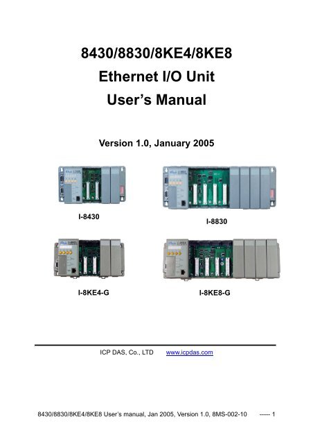
8430/8830/<strong>8KE4</strong>/<strong>8KE8</strong><br />
Ethernet I/O Unit<br />
User’s <strong>Manual</strong><br />
Version 1.0, January 2005<br />
I-8430<br />
I-8830<br />
I-<strong>8KE4</strong>-G<br />
I-<strong>8KE8</strong>-G<br />
<strong>ICP</strong> <strong>DAS</strong>, Co., LTD<br />
www.icpdas.com<br />
8430/8830/<strong>8KE4</strong>/<strong>8KE8</strong> User’s manual, Jan 2005, Version 1.0, 8MS-002-10 ----- 1
8430/8830/<strong>8KE4</strong>/<strong>8KE8</strong><br />
Warranty<br />
All products manufactured by <strong>ICP</strong> <strong>DAS</strong> are under warranty regarding defective materials for<br />
a period of one year, starting from the date of delivery to the original purchaser.<br />
Warning<br />
<strong>ICP</strong> <strong>DAS</strong> assumes no liability for damages resulting from the use of this product. <strong>ICP</strong> <strong>DAS</strong><br />
reserves the right to change this manual at any time without notice. The information<br />
furnished by <strong>ICP</strong> <strong>DAS</strong> is believed to be accurate and reliable. However, no responsibility is<br />
assumed by <strong>ICP</strong> <strong>DAS</strong> for its use, nor for any infringements of patents or other rights of third<br />
parties resulting from its use.<br />
Copyright<br />
Copyright 2005 by <strong>ICP</strong> <strong>DAS</strong>. All rights are reserved.<br />
Trademark<br />
The names used for identification only may be registered trademarks of their respective<br />
companies.<br />
All information about this manual is for items as the table below.<br />
I-8430 4-slots Ethernet I/O unit<br />
I-8430-G<br />
4-slots Ethernet I/O unit (Gray color)<br />
I-8830 8-slots Ethernet I/O unit<br />
I-8830-G<br />
I-<strong>8KE4</strong>-G<br />
I-<strong>8KE8</strong>-G<br />
8-slots Ethernet I/O unit (Gray color)<br />
4-slots Ethernet I/O unit (Gray color)<br />
8-slots Ethernet I/O unit (Gray color)<br />
8430/8830/<strong>8KE4</strong>/<strong>8KE8</strong> User’s manual, Jan 2005, Version 1.0, 8MS-002-10 ----- 2
Table of Contents<br />
Chapter 1. Introduction......................................................................................................5<br />
1.1 Features .................................................................................................................6<br />
1.2 i-8430/i-8830 Hardware Specifications .................................................................10<br />
1.3 i-<strong>8KE4</strong>/i-<strong>8KE8</strong> Hardware Specifications................................................................12<br />
1.4 Front view of 8430/8830 .......................................................................................14<br />
1.5 Front view of <strong>8KE4</strong>/<strong>8KE8</strong>......................................................................................16<br />
1.6 8430/8830/<strong>8KE4</strong>/<strong>8KE8</strong> installation .......................................................................18<br />
1.7 I/O module installation ..........................................................................................21<br />
Chapter 2. Configure the 8430/8830/<strong>8KE4</strong>/<strong>8KE8</strong> and I/O modules ................................25<br />
2.1 Configure the network settings .............................................................................25<br />
2.1.1 By “Configuration Wizard” ...........................................................................25<br />
2.1.2 By MiniOS7 Utility........................................................................................26<br />
2.1.3 By SMMI Menu: Network Configuration.......................................................27<br />
2.2 Creating a virtual COM port to map the I/O modules............................................30<br />
2.3 Configure I/O modules..........................................................................................30<br />
Chapter 3. Using the DCON Protocol..............................................................................33<br />
3.1 The feature of using DCON Protocol ....................................................................33<br />
3.2 Using the TCP protocol directly ............................................................................34<br />
3.3 Via VxComm technology.......................................................................................36<br />
Chapter 4. Software Development ToolKit (free) .............................................................37<br />
4.1 Location of documents and software ....................................................................37<br />
4.2 DCON Utility (DOS) ..............................................................................................39<br />
4.2.1 Procedure for using the DCON Utility (DOS)...............................................39<br />
4.3 DCON DLL ...........................................................................................................40<br />
4.3.1 Procedure for using the DLL........................................................................40<br />
4.3.2 VB Example (Reading an analog input value) .............................................42<br />
4.4 DCON ActiveX ......................................................................................................45<br />
4.4.1 Procedure for using the ActiveX ..................................................................45<br />
4.4.2 VB Example (Reading an analog input value) .............................................46<br />
4.5 DCON LabVIEW ...................................................................................................50<br />
4.5.1 Procedure for using DCON_LabVIEW.........................................................50<br />
4.5.2 LabVIEW Example (Reading multi-channel analog Input value) .................53<br />
4.5.2 LabVIEW Demo Program (Reading multi-channel analog input value) .......54<br />
4.6 DCON Indusoft .....................................................................................................56<br />
4.6.1 Procedure for using the Indusoft bundled driver..........................................56<br />
4.6.2 Indusoft Example (Reading an analog input value) .....................................56<br />
4.7 NAP OPC Server ..................................................................................................61<br />
4.7.1 Introduction..................................................................................................61<br />
4.7.2 Procedure for using the OPC server............................................................62<br />
4.7.3 OPC Server Example (Reading an analog input value)...............................63<br />
Appendix A: Dimensions....................................................................................................66<br />
Appendix B: DCON protocol ..............................................................................................70<br />
B.1 Command Set ......................................................................................................71<br />
B.2 Hardware interface ...............................................................................................80<br />
Appendix C: VxComm technique .......................................................................................81<br />
Appendix D: i-8K and i-87K series I/O modules.................................................................83<br />
Appendix E: Updating firmware and MiniOS7 image .........................................................85<br />
E.1 Access the controller .........................................................................................86<br />
8430/8830/<strong>8KE4</strong>/<strong>8KE8</strong> User’s manual, Jan 2005, Version 1.0, 8MS-002-10 ----- 3
E.2 Updating MiniOS7 image...................................................................................89<br />
E.3 Download firmware ............................................................................................90<br />
8430/8830/<strong>8KE4</strong>/<strong>8KE8</strong> User’s manual, Jan 2005, Version 1.0, 8MS-002-10 ----- 4
Chapter 1. Introduction<br />
The i-8430,i-8830,i-<strong>8KE4</strong> and i-<strong>8KE8</strong> are Ethernet I/O units using DCON Protocol<br />
Firmware E10M_nnn.exe (*1). <strong>ICP</strong><strong>DAS</strong> provides various I/O modules(*2) ,using such as<br />
analog input/output and digital input/output and counter modules which can be used in<br />
remote data acquisition and control application for environment monitoring, power<br />
management, factory automation, etc . via Ethernet communication.<br />
(*1): For detail of E10M_nnn.exe, please refer to<br />
CD:\Napdos\DCON\<strong>8KE4</strong>_<strong>8KE8</strong>\Firmware\Version_Annn.txt<br />
ftp://ftp.icpdas.com/pub/cd/8000cd/napdos/dcon/8ke4_8ke8/firmware/<br />
CD:\Napdos\DCON\8430_8830\Firmware\Version_Annn.txt<br />
ftp://ftp.icpdas.com/pub/cd/8000cd/napdos/dcon/8430_8830/firmware/<br />
(*2): For detail of I/O modules which can be used with 8430/8830/<strong>8KE4</strong>/<strong>8KE8</strong>,<br />
please refer to CD:\Napdos\DCON\IO_Module\<br />
ftp://ftp.icpdas.com/pub/cd/8000cd/napdos/dcon/io_module/<br />
8430/8830/<strong>8KE4</strong>/<strong>8KE8</strong> User’s manual, Jan 2005, Version 1.0, 8MS-002-10 ----- 5
1.1 Features<br />
Ethernet –based Data Acquisition I/O unit<br />
The i-8430,i-8830,i-<strong>8KE4</strong> and i-<strong>8KE8</strong> are Ethernet I/O unit. This feature allows Ethernet<br />
applications to access and control the remote I/O in industrial filed network. And<br />
E10M_nnn.exe or 8KE10.exe is the DCON firmware for the i-8430, i-8830, i-<strong>8KE4</strong> and<br />
i-<strong>8KE8</strong>. Using this firmware, applications can be easily and directly developed using a<br />
TCP program, or via VxComm technology.<br />
ASCII-based protocol (DCON Protocol)<br />
The i-8430,i-8830,i-<strong>8KE4</strong> and i-<strong>8KE8</strong> Ethernet I/O units use the DCON protocol, which<br />
is a request/reply communication protocol used with I-7000/8000/87K series I/O<br />
modules. And is used to access the data from the module using a simple ASCII format.<br />
For example, sending the command “$01M” will query the controller name. The<br />
responding module will reply with a message similar to “!01<strong>8KE4</strong>(cr)” or “!018430(cr)”<br />
For more details regarding the DCON Protocol,<br />
please refer to Appendix B: DCON protocol.<br />
For DCON Protocol about 8000 MCU and 8000 series I/O modules. Please refer to :<br />
CD:\Napdos\DCON\IO_Module\hw_dcon_on_8KUnit<br />
ftp://ftp.icpdas.com/pub/cd/8000cd/napdos/dcon/io_module/hw_dcon_on_8kunit/<br />
Various SDK provided (free)<br />
In order to access the I/O modules that are connected to 8430/8830/<strong>8KE4</strong>/<strong>8KE8</strong>.<br />
Various SDKs are provided, such as: (see Note1, Note2, Note3)<br />
• DLL driver<br />
• ActiveX component<br />
• LabView bundled driver<br />
• Indusoft bundled driver<br />
• Linux driver<br />
• OPC server<br />
Note1: All these SDKs include the DCON Command and can be easily and quickly<br />
integrated into the user's system. Please refer to Chapter 3 for more detail<br />
information.<br />
Note2: When applied to an Ethernet interface, users should first install VxComm utility<br />
when using these SDKs<br />
Note3: DLL, ActiveX, LabView, IndoSoft, OPC server and VxComm utility only support<br />
the windows platform. (Windows 98, Windows NT, Windows 2000, Windows XP)<br />
8430/8830/<strong>8KE4</strong>/<strong>8KE8</strong> User’s manual, Jan 2005, Version 1.0, 8MS-002-10 ----- 6
I/O configurable via the Ethernet<br />
The DCON Utility is used to configure I-7000, I-8000 and I-87K series I/O modules. It<br />
originally communicated with the I/O modules via the COM port. For I/O modules on the<br />
i-8430,i-8830,i-<strong>8KE4</strong> and i-<strong>8KE8</strong>, using the VxComm technique to create a virtual COM<br />
port can let DCON Utility access the I/O modules via the Ethernet. For more details,<br />
please refer to Chapter 3.<br />
Simultaneous access by a maximum of 6 host PCs<br />
Although a maximum of 6 host PCs are allowed simultaneous access, it is<br />
recommended that fewer host PCs are used in order to give better performance and<br />
stability.<br />
Internet<br />
Updateable firmware (via the RS-232 port)<br />
Firmware<br />
Note: the 8430/8830/<strong>8KE4</strong>/<strong>8KE8</strong>’s COM1 port can be used to download firmware,<br />
update the MiniOS image file, and to configure the IP address.<br />
When should the firmware be updated ?<br />
Firmware should be updated when <strong>ICP</strong><strong>DAS</strong> announces<br />
8430/8830/<strong>8KE4</strong>/<strong>8KE8</strong> User’s manual, Jan 2005, Version 1.0, 8MS-002-10 ----- 7
• Support for new I/O modules<br />
• The addition of new functions<br />
• Bug fixes and revision<br />
There is a document (Revision.txt) that records the update information as follows:<br />
For more details, please refer to Appendix E: Updating the firmware and MiniOS7 image.<br />
Dual Bus design to supports i-8K and i-87K series I/O modules<br />
The 8430/8830/<strong>8KE4</strong>/<strong>8KE8</strong> has two types of bus on its back plane. The first is a serial<br />
bus (RS-485 interface) for 87K I/O modules and the second is a parallel bus for 8K I/O<br />
modules. The DCON firmware can support both 8K and 87K series I/O modules. These<br />
two series I/O modules can both be connected into the same I-8000 MCU, and can use<br />
the same DCON command when they are both attached to I-8000 MCU. The modules<br />
for DI, DO, DIO, AI, AO and Counter/Frequency purpose are supported. Other modules,<br />
such as multi-serial port (8112, 8144, 8142, 8144), MMC (8073), motion (8090, 8091),<br />
are not supported. For more details, please refer to Appendix D: i-8K and i-87K series<br />
I/O modules.<br />
For more about I/O module’s information, please refer to<br />
CD:\ Napdos\DCON\IO_Module\hw_dcon_on_8KUnit<br />
ftp://ftp.icpdas.com/pub/cd/8000cd/napdos/dcon/io_module/hw_dcon_on_8kunit/<br />
More flexible I/O combination and Compact、fasten、quick to install<br />
The 8430/8830/<strong>8KE4</strong>/<strong>8KE8</strong> Ethernet I/O units contain either a 4-slot or 8-slot bus to<br />
allow various i/o modules to be connected, removing the need for complex wiring<br />
between i/o modules. Furthermore, various I/O modules can be inserted into the slots at<br />
the same time, such as digital input/output, analog input/output and counter modules,<br />
and each I/O module allows various numbers of channels. For example, with i-8040 or<br />
i-8041, the 8830/<strong>8KE8</strong> provides max 256 digital input or digital output channels.The<br />
module can simply be plugged into the slot and secured to the plastic base using a pair<br />
of locking buttons. The assembly can then be mounted on the control box using DIN rail<br />
clips.<br />
8430/8830/<strong>8KE4</strong>/<strong>8KE8</strong> User’s manual, Jan 2005, Version 1.0, 8MS-002-10 ----- 8
Built-in Watchdog<br />
The built-in watchdog circuit will reset the CPU module if a failure occurs in either the<br />
hardware or software. If the application program does not refresh the watchdog timer<br />
within 0.8 sec, the watchdog circuit will initiate a reset of the CPU.<br />
Input Protection circuitry<br />
The protection circuitry on both the network and power supply protects the system from<br />
external signals such as main spikes and ambient electrical noise. In addition, the<br />
central processing module is isolated from external signals in three ways. This is<br />
achieved through I/O isolation of 3KV, power isolation to 3KV and network isolation to<br />
2KV<br />
High performance integrated power supply<br />
The built-in isolated 20W power supply is rated to perform linearly up to full loading.<br />
Ventilated housing design to work between -25 ~+75℃<br />
The 8430/8830/<strong>8KE4</strong>/<strong>8KE8</strong> is housed in a plastic base box with a column-like ventilator,<br />
that can help to cool the work environment inside the box and allow the<br />
8430/8830/<strong>8KE4</strong>/<strong>8KE8</strong> to operator between -25 ℃ and +75 ℃ .<br />
8430/8830/<strong>8KE4</strong>/<strong>8KE8</strong> User’s manual, Jan 2005, Version 1.0, 8MS-002-10 ----- 9
1.2 i-8430/i-8830 Hardware Specifications<br />
• CPU:<br />
80188 or compatible<br />
16-bits<br />
40MHz<br />
• SRAM:<br />
512KBytes<br />
• Flash ROM:<br />
512KBytes<br />
8 sectors, each sector has 64KBytes<br />
100,000 erase/write cycles<br />
• EEPROM:<br />
2K bytes<br />
8 blocks, each block has 256Bytes<br />
1,000,000 erase/write cycles<br />
• Built-in Watchdog Timer<br />
0.8 seconds<br />
• Ethernet port:<br />
10BaseT NE2000 compatible<br />
PC application use Ethernet to communicate with DCON Firmware.<br />
• COM0 (RS-232):<br />
TXD, RXD, GND, internal serial bus.<br />
Fixed communication speed at 115200 bps.<br />
Used to communicate with 87K modules connected to the slots.<br />
• COM1 (RS-232):<br />
TXD, RXD, GND<br />
Communication speed: programmable, 115200 bps max.<br />
Used to download firmware, update the MiniOS image file and to configure the IP<br />
information<br />
• COM3 (RS-232/485):<br />
RS-232 (TXD, RXD,GND, CTS, RTS) or<br />
RS-485 (DATA+, DATA-)<br />
Communication speed: programmable, 115200 bps max.<br />
• SMMI (Small Man Machine Interface)<br />
5-digit LED display<br />
4 LED indicators<br />
4 push buttons<br />
• I/O expansion slots:<br />
4 slots for 8430<br />
8 slots for 8830<br />
8430/8830/<strong>8KE4</strong>/<strong>8KE8</strong> User’s manual, Jan 2005, Version 1.0, 8MS-002-10 ----- 10
• Mounting mechanism<br />
pannel mounting and din-rail mounting<br />
• Power supply:<br />
20W<br />
• Power requirement:<br />
10 ~ 30 VDC<br />
• Power consumption:<br />
3.9 W (for 8430)<br />
5.1 W (for 8830)<br />
• Operating Environment:<br />
Operating Temp.: –25°C to +75°C.<br />
Storage Temp.: –30°C to +85°C<br />
Humidity: 5 ~ 95%,non-condensing<br />
• Dimension:<br />
230 x 110 x 75.5 mm (for 8430)<br />
354 x 110 x 75.5 mm (for 8830)<br />
For more detailed dimensions, please refer to “Appendix A:Dimensions”.<br />
8430/8830/<strong>8KE4</strong>/<strong>8KE8</strong> User’s manual, Jan 2005, Version 1.0, 8MS-002-10 ----- 11
1.3 i-<strong>8KE4</strong>/i-<strong>8KE8</strong> Hardware Specifications<br />
• CPU:<br />
80186-80 or compatible<br />
16-bits<br />
80MHz<br />
• SRAM:<br />
512KBytes<br />
• Flash ROM:<br />
512KBytes<br />
8 sectors, each sector has 64KBytes<br />
100,000 erase/write cycles<br />
• EEPROM:<br />
2K bytes<br />
8 blocks, each block has 256Bytes<br />
1,000,000 erase/write cycles<br />
• NVRAM:<br />
31 bytes<br />
unlimited erase/write cycles<br />
battery backup for 10 years<br />
• Real time clock:<br />
seconds, minutes, hours, days, month, year<br />
valid from 1980 to 2079<br />
• Built-in Watchdog Timer<br />
0.8 seconds<br />
• Ethernet port:<br />
10BaseT NE2000 compatible<br />
PC application use Ethernet to communicate with DCON Firmware.<br />
• COM0 (RS-232):<br />
TXD, RXD, GND, internal serial bus.<br />
Fixed communication speed at 115200 bps.<br />
Used to communicate with 87K modules connected to the slots.<br />
• COM1 (RS-232):<br />
TXD, RXD, GND<br />
Communication speed: programmable, 115200 bps max.<br />
Used to download firmware, update the MiniOS image file and configure the IP<br />
settings<br />
• SMMI (Small Man Machine Interface)<br />
5-digit LED display<br />
4 LED indicators<br />
4 push buttons<br />
• I/O expansion slots:<br />
4 slots for <strong>8KE4</strong><br />
8 slots for <strong>8KE8</strong><br />
8430/8830/<strong>8KE4</strong>/<strong>8KE8</strong> User’s manual, Jan 2005, Version 1.0, 8MS-002-10 ----- 12
• Mounting mechanism<br />
pannel mounting and din-rail mounting<br />
• Power supply:<br />
20W<br />
• Power requirement:<br />
10 ~ 30 VDC<br />
• Power consumption:<br />
3.9 W (for <strong>8KE4</strong>)<br />
5.1 W (for <strong>8KE8</strong>)<br />
• Operating Environment:<br />
Operating Temp.: –25°C to +75°C.<br />
Storage Temp.: –30°C to +85°C<br />
Humidity: 5 ~ 95%,non-condensing<br />
• Dimension:<br />
230 x 110 x 75.5 mm (for <strong>8KE4</strong>)<br />
354 x 110 x 75.5 mm (for <strong>8KE8</strong>)<br />
For more detailed dimensions, please refer to “Appendix A:Dimensions”.<br />
8430/8830/<strong>8KE4</strong>/<strong>8KE8</strong> User’s manual, Jan 2005, Version 1.0, 8MS-002-10 ----- 13
1.4 Front view of 8430/8830<br />
8430:<br />
Small Man Machine Interface<br />
Power: 10~30VDC<br />
RS-232/485<br />
(COM3)<br />
Initial pin<br />
8830:<br />
RS-232<br />
(COM1)<br />
10M Ethernet port<br />
(COM2)<br />
Small Man Machine Interface<br />
Slot 0 Slot 1 Slot 2 Slot 3<br />
Net ID.<br />
RS-232/485<br />
(COM3)<br />
Power: 10~30VDC<br />
Initial pin<br />
RS-232<br />
(COM1)<br />
10M Ethernet port<br />
(COM2)<br />
Slot 0 Slot 2<br />
Net ID.<br />
Slot 4 Slot 6<br />
Slot 1 Slot 3 Slot 5 Slot 7<br />
8430/8830/<strong>8KE4</strong>/<strong>8KE8</strong> User’s manual, Jan 2005, Version 1.0, 8MS-002-10 ----- 14
Pin assignment of COM1 Port<br />
Pin assignment of COM3 Port<br />
8430/8830/<strong>8KE4</strong>/<strong>8KE8</strong> User’s manual, Jan 2005, Version 1.0, 8MS-002-10 ----- 15
1.5 Front view of <strong>8KE4</strong>/<strong>8KE8</strong><br />
<strong>8KE4</strong>:<br />
Power: 10~30VDC<br />
Small Man Machine Interface<br />
Initial pin<br />
+VS<br />
GND<br />
Input:<br />
10~30VDC<br />
INIT*<br />
Initialize<br />
INIT*COM<br />
Ethernet<br />
10 BaseT<br />
RS-232<br />
(COM1)<br />
10M Ethernet port<br />
Slot 0 Slot 1<br />
Slot 2 Slot 3<br />
<strong>8KE8</strong>:<br />
Small Man Machine Interface<br />
Power: 10~30VDC<br />
Initial pin<br />
+VS<br />
GND<br />
Input:<br />
10~30VDC<br />
INIT*<br />
Initialize<br />
INIT*COM<br />
Ethernet<br />
10 BaseT<br />
RS-232<br />
(COM1)<br />
10M Ethernet port Slot 0 Slot 2 Slot 4<br />
Slot 1 Slot 3<br />
Slot 6<br />
Slot 5 Slot 7<br />
8430/8830/<strong>8KE4</strong>/<strong>8KE8</strong> User’s manual, Jan 2005, Version 1.0, 8MS-002-10 ----- 16
Pin assignment of COM1 Port<br />
8430/8830/<strong>8KE4</strong>/<strong>8KE8</strong> User’s manual, Jan 2005, Version 1.0, 8MS-002-10 ----- 17
1.6 8430/8830/<strong>8KE4</strong>/<strong>8KE8</strong> installation<br />
Step1: Mount the I/O unit<br />
Method (a): using screw panel mounting<br />
Step1 (b): Mount the I/O unit (method b: DIN-rail mounting)<br />
Method (b): DIN-Rail mounting<br />
Frame Ground<br />
DIN-Rail Clips<br />
8430/8830/<strong>8KE4</strong>/<strong>8KE8</strong> User’s manual, Jan 2005, Version 1.0, 8MS-002-10 ----- 18
Step2: Attach power supply (10 ~ 30 VDC)<br />
The diagrams below show the basic wiring for the Ethernet I/O.<br />
8430/8830/<strong>8KE4</strong>/<strong>8KE8</strong> User’s manual, Jan 2005, Version 1.0, 8MS-002-10 ----- 19
Step3: Check the LED display<br />
The LED constantly shows IP address, Baud Rate, Data Bit Format ..etc as following<br />
sequences.<br />
11111.<br />
1.27.00<br />
27: Free-sockets=27<br />
00: No client connects to this 8000E<br />
1. 192<br />
44444.<br />
The IP is<br />
192.168.255.1<br />
2. 168<br />
8. 821 COM8: data=8, odd parity, stop=1<br />
3. 255<br />
2. 712<br />
COM2: data=7, even parity, stop=2<br />
4. 1<br />
1. 801<br />
COM1: data=8, no parity, stop=1<br />
22222.<br />
33333.<br />
Baud Rate of COM1=9600<br />
1. 96 2. 96<br />
Baud Rate of COM2=9600<br />
8430/8830/<strong>8KE4</strong>/<strong>8KE8</strong> User’s manual, Jan 2005, Version 1.0, 8MS-002-10 ----- 20
1.7 I/O module installation<br />
Step1: Read the document at the following location<br />
For I-8000 series modules the files are located at:<br />
CD:\ Napdos\DCON\IO_Module\hw_dcon_on_8KUnit\8k<br />
ftp://ftp.icpdas.com/pub/cd/8000cd/napdos/dcon/io_module/hw_dcon_on_8kunit/8k/<br />
For I-87K series modules the files are located at:<br />
CD:\ Napdos\DCON\IO_Module\hw_dcon_on_8KUnit\87k<br />
ftp://ftp.icpdas.com/pub/cd/8000cd/napdos/dcon/io_module/hw_dcon_on_8kunit/87k/<br />
These *.chm files include the I/O module specifications, pin assignments, wire connections.<br />
For example, the pin assignments and wire connections are as follows.<br />
8430/8830/<strong>8KE4</strong>/<strong>8KE8</strong> User’s manual, Jan 2005, Version 1.0, 8MS-002-10 ----- 21
Pin assignment<br />
8430/8830/<strong>8KE4</strong>/<strong>8KE8</strong> User’s manual, Jan 2005, Version 1.0, 8MS-002-10 ----- 22
Wire Connection<br />
8430/8830/<strong>8KE4</strong>/<strong>8KE8</strong> User’s manual, Jan 2005, Version 1.0, 8MS-002-10 ----- 23
Step2: Connect the wire<br />
Step3: Insert the I/O module into the <strong>8KE4</strong>/<strong>8KE8</strong><br />
8430/8830/<strong>8KE4</strong>/<strong>8KE8</strong> User’s manual, Jan 2005, Version 1.0, 8MS-002-10 ----- 24
Chapter 2. Configure the 8430/8830/<strong>8KE4</strong>/<strong>8KE8</strong> and I/O<br />
modules<br />
Before using the 8430/8830/<strong>8KE4</strong>/<strong>8KE8</strong> and any I/O modules connected to it, the following<br />
settings must be configured:<br />
• Networking settings: IP, Mask, Gateway of 8430/8830/<strong>8KE4</strong>/<strong>8KE8</strong><br />
• Power on value of AO, DO modules<br />
• Safe value of AO, DO modules<br />
• Input range of AI modules<br />
• Noise filter of AI modules<br />
• Check sum of all communication protocol<br />
The most important thing at the beginning stage is the network setting. After assigning the<br />
network setting, the VxComm Utility can be used to create a virtual COM port to map the<br />
8430/8830/<strong>8KE4</strong>/<strong>8KE8</strong>, and then the DCON utility can be used to configure other settings.<br />
2.1 Configure the network settings<br />
Network settings can only be configured via the RS-232 COM Port.<br />
There are three tools that can be used to configure the network settings of<br />
8430/8830/<strong>8KE4</strong>/<strong>8KE8</strong>.<br />
• By “Configuration Wizard“<br />
• By “MiniOS7 Utility”<br />
• By “SMMI Menu”<br />
2.1.1 By “Configuration Wizard”<br />
The “Configuration Wizard” gives step by step information for configuring the network<br />
settings. The wizard is most useful for detecting the host PCs network settings, searching<br />
the local network to locate a valid IP, Mask and Gateway address. Using the “Configuration<br />
Wizard”, allows automatic detection of the important settings, removing the need to contact<br />
system administrators for support.<br />
Step1: Use CA-0915 to connect COM1 of 8430/8830/<strong>8KE4</strong>/<strong>8KE8</strong> to COM1/2 of the host<br />
PC.<br />
Step2: Install PCDiag to the host PC by running<br />
CD:\Napdos\7188e\tcp\PCDiag<br />
Step3: Follow the instructions given by the “Configuration Wizard” until the following<br />
window appears<br />
8430/8830/<strong>8KE4</strong>/<strong>8KE8</strong> User’s manual, Jan 2005, Version 1.0, 8MS-002-10 ----- 25
3<br />
Step4: Open the COM port and then click “Configure” to set the IP, Mask, Gateway to<br />
8430/8830/<strong>8KE4</strong>/<strong>8KE8</strong>.<br />
4.1<br />
4.2<br />
4.21<br />
Step5: Exit the “Configure Wizard” and then restart the 8430/8830/<strong>8KE4</strong>/<strong>8KE8</strong> for the new<br />
settings.<br />
2.1.2 By MiniOS7 Utility<br />
The MiniOS7 Utility is used to download files and update the OS image to the<br />
8430/8830/<strong>8KE4</strong>/<strong>8KE8</strong>. It can also be used to configure the network and COM port settings.<br />
In contrast to “Configure Wizard”, users must have valid IP, Mask, Gateway information and<br />
must manually enter it into the text box provided.<br />
Step1: Use CA-0915 to connect COM1 of 8430/8830/<strong>8KE4</strong>/<strong>8KE8</strong> to COM1/2 of the host<br />
PC.<br />
Step2: Install the MiniOS7 Utility on the host PC by running<br />
CD:\Napdos\MiniOS7\Utility\MiniOS7_Utility\MiniOS7_Utility.exe<br />
8430/8830/<strong>8KE4</strong>/<strong>8KE8</strong> User’s manual, Jan 2005, Version 1.0, 8MS-002-10 ----- 26
Step3: Run the MiniOS7 Utility and click “Configuration”<br />
Step4: Exit the MiniOS7 Utility and then restart the 8430/8830/<strong>8KE4</strong>/<strong>8KE8</strong> for the new<br />
settings.<br />
2.1.3 By SMMI Menu: Network Configuration<br />
L1 L2<br />
L3 POWER<br />
MODE UP DOWN SET<br />
Step1: Accessing the SMMI menu<br />
The LEDs normally show system information. Pressing the “Mode” and Set buttons for<br />
more than 1.5 seconds will allow access to the SMMI menu. The LED menu has 2 levels.<br />
By following the menu tree map, the cursor position in the SMMI menu can be changed.<br />
8430/8830/<strong>8KE4</strong>/<strong>8KE8</strong> User’s manual, Jan 2005, Version 1.0, 8MS-002-10 ----- 27
Step2: The SMMI menu tree<br />
The SMMI menu is designed to allow the users to set the network settings (IP, Mask,<br />
Gateway) without requiring a host PC.<br />
Following is the SMMI menu tree.<br />
Cursor position<br />
8430/8830/<strong>8KE4</strong>/<strong>8KE8</strong> User’s manual, Jan 2005, Version 1.0, 8MS-002-10 ----- 28
Step3: Selection items that can be changed<br />
There are four items in the menu, and there are three items (IP, MASK, GATEWAY) that can<br />
be changed. When entering the LED menu, the initial status is at level 1 and the cursor<br />
position is at position 1 (IP) .<br />
L1 L2<br />
L3 POWER<br />
MODE UP DOWN SET<br />
Only the “Mode” and “Set” buttons are available in this situation. By pressing the “Mode”<br />
button, the cursor can be moved with in same level. By pressing the “Set” button, the<br />
position will be changed to another level in order to execute the action selected by the uses.<br />
8430/8830/<strong>8KE4</strong>/<strong>8KE8</strong> User’s manual, Jan 2005, Version 1.0, 8MS-002-10 ----- 29
2.2 Creating a virtual COM port to map the I/O modules<br />
Step1: Wire the 8430/8830/<strong>8KE4</strong>/<strong>8KE8</strong> and configure its network settings (IP, Mask,<br />
Gateway)<br />
Step2: Install the VxComm driver appropriate for your PC (95/98/NT/2000/XP)<br />
CD:\Napdos\7188e\tcp\VxComm\Driver(PC)\<br />
Step3: Run the VxComm Utility and connect to the 8430/8830/<strong>8KE4</strong>/<strong>8KE8</strong><br />
Step4: Map the “Port I/O” to a virtual COM port.<br />
Step5: Exit the VxComm Utility<br />
2.3 Configure I/O modules<br />
The DCON Utility is used to configure I-7000, I-8000 and I-87K series I/O modules and<br />
communicates with I/O modules via the COM port. For I/O modules on the<br />
8430/8830/<strong>8KE4</strong>/<strong>8KE8</strong>, using the VxComm technique can let DCON Utility to access the<br />
I/O modules via the Ethernet.<br />
DCON Utility<br />
Main functions<br />
Configuring modules<br />
Baudrate<br />
Address<br />
Check sum<br />
Power on value<br />
Safe value… etc.<br />
Testing I/O actions<br />
Modules supported:<br />
i-7000/i-8000/i-87K series<br />
(with DCON protocol)<br />
OS supported:<br />
Windows 98/NT/2000/XP<br />
File location:<br />
CD:\Napdos\Driver\DCON_Utility<br />
8430/8830/<strong>8KE4</strong>/<strong>8KE8</strong> User’s manual, Jan 2005, Version 1.0, 8MS-002-10 ----- 30
Step1: Wire the 8430/8830/<strong>8KE4</strong>/<strong>8KE8</strong> and configure its network settings (IP, Mask,<br />
Gateway)<br />
Step2: Create a virtual COM port (for example: COM3) to map the I/O modules<br />
Step3: Install the DCON Utililty by running<br />
CD:\Napdos\Driver\DCON_Utility\Setup\setup.exe and then run it.<br />
3.1<br />
4.1<br />
4.2<br />
4.3<br />
8430/8830/<strong>8KE4</strong>/<strong>8KE8</strong> User’s manual, Jan 2005, Version 1.0, 8MS-002-10 ----- 31
Step4: Change the COM port to the virtual COM port. Note: for 8430/8830/<strong>8KE4</strong>/<strong>8KE8</strong>,<br />
the Baud Rate is unimportant. Any Baud Rate setting can be used.<br />
Step5: Search for the I/O modules on the 8430/8830/<strong>8KE4</strong>/<strong>8KE8</strong>. After the modules<br />
are found, individually click on them to configure them.<br />
5.1<br />
5.2<br />
5.3<br />
5.4<br />
Note<br />
Note: All the 87K I/O modules that connected to 8430/8830/<strong>8KE4</strong>/<strong>8KE8</strong> are<br />
rename to 80xx(87K)<br />
8430/8830/<strong>8KE4</strong>/<strong>8KE8</strong> User’s manual, Jan 2005, Version 1.0, 8MS-002-10 ----- 32
Chapter 3. Using the DCON Protocol<br />
3.1 The feature of using DCON Protocol<br />
The DCON firmware which uses ASCII Command provided with the 8430/8830/<strong>8KE4</strong>/<strong>8KE8</strong>,<br />
is easy to use and most of application can be developed using toolkits supported by<br />
<strong>ICP</strong><strong>DAS</strong>, such as DLL, ActivateX or OPC Server, which can shorten their development<br />
time.<br />
8430/8830/<strong>8KE4</strong>/<strong>8KE8</strong> User’s manual, Jan 2005, Version 1.0, 8MS-002-10 ----- 33
3.2 Using the TCP protocol directly<br />
Supports the DCON communication protocol on the Ethernet port. A TCP program can be<br />
used to develop Ethernet Applications to communicate with Ethernet port 9999 of the<br />
8430/8830/<strong>8KE4</strong>/<strong>8KE8</strong>.<br />
The following steps show how to use VB Winsock component .<br />
Step 1. Connect to the Ethernet controller<br />
Step 2. Send command with cr<br />
Step 3. Receive data from Ethernet controller<br />
Step 4. Close connection.<br />
8430/8830/<strong>8KE4</strong>/<strong>8KE8</strong> User’s manual, Jan 2005, Version 1.0, 8MS-002-10 ----- 34
The result will be as below.<br />
This TCP application uses the DCON Protocol to communicate with Ethernet port 9999 of<br />
the i-<strong>8KE4</strong> Ethernet I/O controller .<br />
The demo program can be found at<br />
CD:\Napdos\8000\843x883x\TCP\Xserver\Client\Common\VB5\Client4<br />
Or on the internet at<br />
ftp://ftp.icpdas.com/pub/cd/8000cd/napdos/8000/843x883x/tcp/xserver/client/common/vb5/<br />
client4/<br />
8430/8830/<strong>8KE4</strong>/<strong>8KE8</strong> User’s manual, Jan 2005, Version 1.0, 8MS-002-10 ----- 35
3.3 Via VxComm technology<br />
VxComm (“Virtual Communication Port”) is a technique that allows a COM Port to be<br />
used to communicate with an <strong>ICP</strong><strong>DAS</strong> Ethernet control unit. The Diagram below show<br />
how to use VxComm Utility to map PC’s COM Port to 8430/8830/<strong>8KE4</strong>/<strong>8KE8</strong>’s Ethernet<br />
I/O Port.<br />
8430/8830/<strong>8KE4</strong>/<strong>8KE8</strong> User’s manual, Jan 2005, Version 1.0, 8MS-002-10 ----- 36
Chapter 4. Software Development ToolKit (free)<br />
4.1 Location of documents and software<br />
The location of all documents and software related to the 8430/8830/<strong>8KE4</strong>/<strong>8KE8</strong> are shown<br />
in the following directory tree. The relevant file can quickly be located by referring to the<br />
tree.<br />
Various SDKs are provided for the DCON protocol, such as DLL, ActiveX, Labview driver,<br />
Indusoft driver, Linux driver, OPC server, etc. Each SDK also contains a number of helpful<br />
free demo programs and documents, which can be found on the CD included in the<br />
package, or can be downloaded from the <strong>ICP</strong> <strong>DAS</strong> web site or FTP site..<br />
When planning the development of a system, appropriate software solutions should be<br />
chosen to suit different situations. Following chart shows the relation between the software<br />
solution and the SDK provided. Refer to the chart to find a solution to meet your<br />
requirements.<br />
8430/8830/<strong>8KE4</strong>/<strong>8KE8</strong> User’s manual, Jan 2005, Version 1.0, 8MS-002-10 ----- 37
The diagram below show the architecture of the SDK.<br />
Note: All the above SDKs are based on VxComm technology when using an Ethernet<br />
interface.<br />
8430/8830/<strong>8KE4</strong>/<strong>8KE8</strong> User’s manual, Jan 2005, Version 1.0, 8MS-002-10 ----- 38
4.2 DCON Utility (DOS)<br />
DCON Utility (DOS)<br />
DCON Utility (DOS version)<br />
Supported modules:<br />
i-7000/8000/87K series<br />
(with DCON protocol)<br />
Supported demos:<br />
C<br />
Supported OS:<br />
DOS<br />
File location:<br />
CD:\Napdos\Driver\DCON_DOS<br />
4.2.1 Procedure for using the DCON Utility (DOS)<br />
Step 1: Read the basic and important documents<br />
Readme.txt: contains the basic and important information, including:<br />
• What is DCON Utility (DOS)<br />
• What files are installed on the PC<br />
Step 2: Read manuals for how to start<br />
DCON_DOS.pdf:<br />
Explains how to use the DOS version utility to diagnose/configure the I/O modules<br />
and how to use the C language to develop your first program running under DOS.<br />
The manual explains following details:<br />
• How to include the lib to C<br />
• How to develop a program in C<br />
• Demo list<br />
• Function descriptions and usage<br />
Step 3: Run DCON_DOS\Diag\test.exe to diagnose the I/O modules.<br />
8430/8830/<strong>8KE4</strong>/<strong>8KE8</strong> User’s manual, Jan 2005, Version 1.0, 8MS-002-10 ----- 39
4.3 DCON DLL<br />
DCON DLL<br />
DLL library<br />
Supported modules:<br />
i-7000/8000/87K series<br />
(with DCON protocol)<br />
Supported demos:<br />
VB/VC/BCB/Delphi<br />
Supported OS:<br />
Windows 98/NT/2K/XP<br />
File location:<br />
CD:\Napdos\Driver\DCON_DLL<br />
4.3.1 Procedure for using the DLL<br />
Step 1: Read the basic and important documents<br />
Readme.txt: contains most basic and important information, including:<br />
• What is DCON DLL<br />
• What files are installed on the PC<br />
• The directory tree installed on the PC<br />
• Demo list<br />
WhatsNew.txt: contains the version/reversion history information, including<br />
• Bugs fixed<br />
• Demos added or modified<br />
• Updated DLL details<br />
8430/8830/<strong>8KE4</strong>/<strong>8KE8</strong> User’s manual, Jan 2005, Version 1.0, 8MS-002-10 ----- 40
Step 2: Install the DCON DLL by executing:<br />
CD:\Napdos\Driver\DCON_DLL\Setup\setup.exe<br />
After installation, all related information can be found below<br />
Step3: Read manuals for how to start<br />
QuickStart<strong>Manual</strong>.pdf:<br />
Explains how to develop your first program using the DLL.<br />
DCON_DLL.pdf explains the following details<br />
• How to include the DLL in VB/VC/Delphi/BCB<br />
• How to develop a program in VB/VC/Delphi/BCB<br />
• Demo list<br />
• Function descriptions and usage<br />
FAQ.pdf:<br />
Gives solutions to frequently asked questions.<br />
Step 3: Run the demo programs to test the I/O module and learn the functions<br />
8430/8830/<strong>8KE4</strong>/<strong>8KE8</strong> User’s manual, Jan 2005, Version 1.0, 8MS-002-10 ----- 41
4.3.2 VB Example (Reading an analog input value)<br />
The following is an example of reading analog values from an I-87017 inserted in slot 0 of<br />
an 8kE4/<strong>8KE8</strong>.<br />
Step 1: Wire the 8430/8830/<strong>8KE4</strong>/<strong>8KE8</strong> and configure its network settings (IP, Mask,<br />
Gateway)<br />
Step 2: Run the VxComm Utility to create a virtual COM port (e.g. COM3) to map the<br />
8430/8830/<strong>8KE4</strong>/<strong>8KE8</strong><br />
Step 3: Run the DCON Utility to configure the I/O modules<br />
Step 4: Run VB and create a new project (.exe project)<br />
Step 5: Add I7000.bas to the project<br />
Step 6: Arrange all the components on the form<br />
8430/8830/<strong>8KE4</strong>/<strong>8KE8</strong> User’s manual, Jan 2005, Version 1.0, 8MS-002-10 ----- 42
Step 7: Write the program code<br />
VB Step 3<br />
VB Step 1<br />
VB Step 2<br />
8430/8830/<strong>8KE4</strong>/<strong>8KE8</strong> User’s manual, Jan 2005, Version 1.0, 8MS-002-10 ----- 43
Step 8: Run the project.<br />
8430/8830/<strong>8KE4</strong>/<strong>8KE8</strong> User’s manual, Jan 2005, Version 1.0, 8MS-002-10 ----- 44
4.4 DCON ActiveX<br />
DCON ActiveX<br />
ActiveX (ocx) component<br />
Supported modules:<br />
i-7000/8000/87K series<br />
(with DCON protocol)<br />
Supported demos:<br />
VB/VC/BCB/Delphi<br />
Supported OS:<br />
Windows 98/NT/2K/XP<br />
File location:<br />
CD:\Napdos\Driver\DCON_ActiveX<br />
4.4.1 Procedure for using the ActiveX<br />
Step 1: Read most basic and important documents<br />
Readme.txt: contains the basic and important information, including:<br />
• What is DCON ActiveX<br />
• What files are installed on the PC<br />
• The directory tree installed on the PC<br />
• Demo list<br />
WhatsNew.txt: contains the version/reversion history information, including:<br />
• Bugs fixed<br />
• Demos added or modified<br />
• Updated ActiveX (ocx) details<br />
8430/8830/<strong>8KE4</strong>/<strong>8KE8</strong> User’s manual, Jan 2005, Version 1.0, 8MS-002-10 ----- 45
Step 2: Install the DCON ActiveX by executing:<br />
CD:\Napdos\Driver\DCON_ActiveX\Setup\setup.exe<br />
After installation, all related information can be found below<br />
Step 3: Read the manuals describing how to start<br />
InstallOCX.pdf:<br />
Explains how to install/uninstall the ActiveX (ocx) component in<br />
VB/VC/Delphi/BCB<br />
DCON_ActiveX.pdf explains the following details:<br />
• How to include the ActiveX(ocx) in VB/VC/Delphi/BCB<br />
• How to develop a program in VB/VC/Delphi/BCB<br />
• Demo list<br />
• Function descriptions and usage<br />
Step 4: Run the demo programs to test the I/O module and learn the functions<br />
4.4.2 VB Example (Reading an analog input value)<br />
The following is an example of reading analog values from an I-87017 inserted in slot 0 of<br />
an 8430/8830/<strong>8KE4</strong>/<strong>8KE8</strong>.<br />
Step 1: Wire the 8430/8830/<strong>8KE4</strong>/<strong>8KE8</strong> and configure its network settings (IP, Mask,<br />
Gateway)<br />
Step 2: Run the VxComm Utility to create a virtual COM port (e.g. COM3) to map the<br />
<strong>8KE4</strong>/<strong>8KE8</strong><br />
Step 3: Run the DCON Utility to configure the I/O module<br />
8430/8830/<strong>8KE4</strong>/<strong>8KE8</strong> User’s manual, Jan 2005, Version 1.0, 8MS-002-10 ----- 46
Step 4: Run VB and create a new project (.exe project)<br />
Step 5: Add the ActiveX (ocx) component to the project<br />
5.1<br />
5.2<br />
5.3<br />
8430/8830/<strong>8KE4</strong>/<strong>8KE8</strong> User’s manual, Jan 2005, Version 1.0, 8MS-002-10 ----- 47
Step 6: Arrange all the components on the form<br />
Step 7: Write the program code<br />
VB Step 2<br />
VB Step 3<br />
VB Step 1<br />
8430/8830/<strong>8KE4</strong>/<strong>8KE8</strong> User’s manual, Jan 2005, Version 1.0, 8MS-002-10 ----- 48
Step 8: Run the project<br />
8430/8830/<strong>8KE4</strong>/<strong>8KE8</strong> User’s manual, Jan 2005, Version 1.0, 8MS-002-10 ----- 49
4.5 DCON LabVIEW<br />
DCON LabVIEW<br />
Bundled driver for LabVIEW<br />
Supported modules:<br />
i-7000/8000/87K series<br />
(with DCON protocol)<br />
Supported OS:<br />
Windows 98/NT/2K/XP<br />
File location:<br />
CD:\Napdos\Driver\DCON_Labview<br />
4.5.1 Procedure for using DCON_LabVIEW<br />
Step 1: Install the DCON LabVIEW by executing:<br />
CD:\Napdos\Driver\ DCON_Labview\ DCON_Labview.exe<br />
After installation, the related information can be found as below:<br />
8430/8830/<strong>8KE4</strong>/<strong>8KE8</strong> User’s manual, Jan 2005, Version 1.0, 8MS-002-10 ----- 50
8000Demo: Demo programs for I-8000 I/O modules.<br />
8000.llb: LabVIEW library contains all sub-vi for I-8000 I/O modules<br />
CallDLLinLabVIEW.pdf: Explains how to call a sub-vi of in LabVIEW.<br />
DCON_DLL.pdf: Descriptions of all sub-function in DCON_DLL<br />
8430/8830/<strong>8KE4</strong>/<strong>8KE8</strong> User’s manual, Jan 2005, Version 1.0, 8MS-002-10 ----- 51
Step 2: Create a new LabVIEW program. Refer the DCON_DLL.pdf about detail description<br />
of the sub-vi and where to select the sub-vi in various librarys of DCON_LabVIEW.<br />
Step3: Select the sub-vi form Functions Palette >> Select a VI…<br />
8430/8830/<strong>8KE4</strong>/<strong>8KE8</strong> User’s manual, Jan 2005, Version 1.0, 8MS-002-10 ----- 52
4.5.2 LabVIEW Example (Reading multi-channel analog<br />
Input value)<br />
Step4: Select the target *.lib file (LabVIEW library file)<br />
Step5: Select the desired sub-vi<br />
8430/8830/<strong>8KE4</strong>/<strong>8KE8</strong> User’s manual, Jan 2005, Version 1.0, 8MS-002-10 ----- 53
Step6 : Put the icon of selected sub-vi on Block Diagram, refer the “Help” >> “Show Help”<br />
or “DCON_DLL.pdf” in step1 for detail.<br />
Step7 : Draw the data flow of sub-vi.<br />
4.5.2 LabVIEW Demo Program (Reading multi-channel<br />
analog input value)<br />
Step 1: Select the appropriate demo program by the name according with module’s<br />
function.<br />
8430/8830/<strong>8KE4</strong>/<strong>8KE8</strong> User’s manual, Jan 2005, Version 1.0, 8MS-002-10 ----- 54
Step2: Set the parameters<br />
2.1<br />
2.2<br />
You could also refer the “Help”>>”Show Context Help” for getting the simple description of<br />
those parameters.<br />
Step3: Run the demo.<br />
8430/8830/<strong>8KE4</strong>/<strong>8KE8</strong> User’s manual, Jan 2005, Version 1.0, 8MS-002-10 ----- 55
4.6 DCON Indusoft<br />
DCON Indusoft<br />
Bundled driver for Indusoft<br />
Supported Module:<br />
i-7000/8000/87K series<br />
(with DCON protocol)<br />
Supported OS:<br />
Windows 98/NT/2K/XP/CE<br />
File location:<br />
CD:\Napdos\Driver\DCON_Indusoft<br />
4.6.1 Procedure for using the Indusoft bundled driver<br />
Step 1: Read the basic and important documents<br />
Readme.txt: contains the basic and important information, including:<br />
• Files on the shipped CD<br />
Reversion.txt: contains the reversion information, including<br />
• Bugs fixed<br />
• New modules supported<br />
Step 2: Install the Indusoft bundled driver by executing<br />
CD:\Napdos\Driver\DCON_Indusoft\Setup\setup.exe<br />
Step 3: Read the manuals describing how to start<br />
The DCON.pdf user’s manual describes how to use the Indusoft bundled driver<br />
Step 4: Run the demo programs (<strong>ICP</strong>DriverTest.zip) to test I/O modules and learn the<br />
functions<br />
4.6.2 Indusoft Example (Reading an analog input value)<br />
The following is an example of reading analog values from an I-87017 inserted in slot 0 of<br />
an 8430/8830/<strong>8KE4</strong>/<strong>8KE8</strong>.<br />
Step 1: Wire the 8430/8830/<strong>8KE4</strong>/<strong>8KE8</strong> and configure its network settings (IP, Mask,<br />
Gateway)<br />
Step 2: Run the VxComm Utility to create a virtual COM port (e.g. COM3) to map the<br />
8430/8830/<strong>8KE4</strong>/<strong>8KE8</strong><br />
8430/8830/<strong>8KE4</strong>/<strong>8KE8</strong> User’s manual, Jan 2005, Version 1.0, 8MS-002-10 ----- 56
Step 3: Run the DCON Utility to configure the I/O modules<br />
Step 4: Run Indusoft and create a new project<br />
Step 5: Include the DCON driver<br />
5.1<br />
5.2<br />
5.3<br />
5.4<br />
8430/8830/<strong>8KE4</strong>/<strong>8KE8</strong> User’s manual, Jan 2005, Version 1.0, 8MS-002-10 ----- 57
Step 6: Configure the DCON driver<br />
6.1<br />
6.2<br />
6.3<br />
8430/8830/<strong>8KE4</strong>/<strong>8KE8</strong> User’s manual, Jan 2005, Version 1.0, 8MS-002-10 ----- 58
Step7: Insert tags to connect to I/O modules<br />
The address format is [Address : ModuleID : Slot : Channel]<br />
7.1<br />
7.2<br />
Step8: Arrange all the components on the form<br />
8430/8830/<strong>8KE4</strong>/<strong>8KE8</strong> User’s manual, Jan 2005, Version 1.0, 8MS-002-10 ----- 59
Step9: Double click the text box to assign a tag to it<br />
9.1<br />
9.2<br />
Step10: Run the project<br />
8430/8830/<strong>8KE4</strong>/<strong>8KE8</strong> User’s manual, Jan 2005, Version 1.0, 8MS-002-10 ----- 60
4.7 NAP OPC Server<br />
NAP OPC server<br />
OPC Server<br />
Supported module:<br />
i-7000/8000/87K series<br />
(with DCON protocol)<br />
Modbus embedded controller<br />
ISaGRAF embedded controller<br />
Supported OS:<br />
Windows 98/NT/2K/XP/CE<br />
File location:<br />
CD:\Napdos\NapOPCSvr<br />
4.7.1 Introduction<br />
OPC (OLE for Process Control) is the first standard resulting from the collaboration of a<br />
number of leading worldwide automation suppliers working in cooperation with Microsoft.<br />
Originally based on Microsoft's OLE COM (component object model) and DCOM<br />
(distributed component object model) technologies, the specification defined a standard set<br />
of objects, interfaces and methods for use in process control and manufacturing automation<br />
applications to facilitate interoperability. The COM/DCOM technologies provided the<br />
framework for software products to be developed. There are now hundreds of OPC Data<br />
Access servers and clients.<br />
8430/8830/<strong>8KE4</strong>/<strong>8KE8</strong> User’s manual, Jan 2005, Version 1.0, 8MS-002-10 ----- 61
4.7.2 Procedure for using the OPC server<br />
Step 1: Read the basic and important documents<br />
Readme.txt: contains the basic and important information, including<br />
• Files on the shipped CD<br />
Reversion.txt: contains the reversion information, including<br />
• Bugs fixed<br />
• New modules supported<br />
Step 2: Install the OPC server by executing<br />
CD:\Napdos\NapOPCSvr\NapOPCServer.exe<br />
Note: If there is an older version of Nap OPC Server installed on the PC, It must<br />
be uninstalled before installing the new version.<br />
Step 3: Read the manuals describing how to start<br />
The NapOPCSvr.pdf is the user’s manual describing how to use the OPC server<br />
8430/8830/<strong>8KE4</strong>/<strong>8KE8</strong> User’s manual, Jan 2005, Version 1.0, 8MS-002-10 ----- 62
4.7.3 OPC Server Example (Reading an analog input<br />
value)<br />
The following is an example of reading analog values from an I-87017 inserted in slot 0 of<br />
an 8430/8830/<strong>8KE4</strong>/<strong>8KE8</strong>.<br />
Step 1: Wire the8430/8830/<strong>8KE4</strong>/<strong>8KE8</strong> and configure its network settings (IP, Mask,<br />
Gateway)<br />
Step 2: Run the VxComm Utility to create a virtual COM port (e.g. COM3) to map the<br />
8430/8830/<strong>8KE4</strong>/<strong>8KE8</strong><br />
Step 3: Run the DCON Utility to configure the I/O modules<br />
8430/8830/<strong>8KE4</strong>/<strong>8KE8</strong> User’s manual, Jan 2005, Version 1.0, 8MS-002-10 ----- 63
Step 4: Run the OPC server to search for I/O modules on COM3<br />
4.1<br />
4.2<br />
4.3<br />
4.4<br />
8430/8830/<strong>8KE4</strong>/<strong>8KE8</strong> User’s manual, Jan 2005, Version 1.0, 8MS-002-10 ----- 64
Step 5: Save the configuration and close the OPC Server<br />
Step 6: Run SCADA software to connect to the OPC Server<br />
The OPC Server user’s manual lists the procedures for the following SCADA software:<br />
• Labview<br />
• National<br />
• WIZCON<br />
• iFix<br />
• Indusoft<br />
• Citect<br />
Please refer to “Chapter 4 Connecting to the OPC Server” for more details.<br />
8430/8830/<strong>8KE4</strong>/<strong>8KE8</strong> User’s manual, Jan 2005, Version 1.0, 8MS-002-10 ----- 65
Appendix A: Dimensions<br />
i-8430 :<br />
Back View<br />
Side View<br />
Top View<br />
+VS<br />
GND<br />
Input:<br />
10~30VDC<br />
INIT*<br />
Initialize<br />
INIT*COM<br />
Ethernet<br />
10 BaseT<br />
Front View<br />
8430/8830/<strong>8KE4</strong>/<strong>8KE8</strong> User’s manual, Jan 2005, Version 1.0, 8MS-002-10 ----- 66
i-8830:<br />
Back View<br />
Side View<br />
Top View<br />
+VS<br />
GND<br />
Input:<br />
10~30VDC<br />
INIT*<br />
Initialize<br />
INIT*COM<br />
Ethernet<br />
10 BaseT<br />
Front View<br />
8430/8830/<strong>8KE4</strong>/<strong>8KE8</strong> User’s manual, Jan 2005, Version 1.0, 8MS-002-10 ----- 67
i-<strong>8KE4</strong> :<br />
Back View<br />
Side View<br />
Top View<br />
+VS<br />
GND<br />
Input:<br />
10~30VDC<br />
INIT*<br />
Initialize<br />
INIT*COM<br />
Ethernet<br />
10 BaseT<br />
Front View<br />
8430/8830/<strong>8KE4</strong>/<strong>8KE8</strong> User’s manual, Jan 2005, Version 1.0, 8MS-002-10 ----- 68
i-<strong>8KE8</strong>:<br />
Back View<br />
Side View<br />
Top View<br />
+VS<br />
GND<br />
Input:<br />
10~30VDC<br />
INIT*<br />
Initialize<br />
INIT*COM<br />
Ethernet<br />
10 BaseT<br />
Front View<br />
8430/8830/<strong>8KE4</strong>/<strong>8KE8</strong> User’s manual, Jan 2005, Version 1.0, 8MS-002-10 ----- 69
Appendix B: DCON protocol<br />
The DCON protocol is a request/reply communication protocol for the I-7000/8000/87K<br />
series I/O modules, and uses a simple ASCII format such as $AAN, $AASi6, #AAN,<br />
#AASiCj,..., etc. The protocol format is defined as follows:<br />
Basic Command Format<br />
Command Format:<br />
Leading Character Module Address Command [CHKSUM] CR<br />
Response Format:<br />
Leading Character [Module Address] [Data] [CHKSUM] CR<br />
The Leading Character can include ‘@’, ‘#’, ‘$’, ‘%’, ‘~’, ‘!’<br />
Checksum A 2-character checksum and is present when the checksum option is enabled.<br />
Address 0x00 ~ 0xFF<br />
CR<br />
Carriage return (0x0D)<br />
8430/8830/<strong>8KE4</strong>/<strong>8KE8</strong> User’s manual, Jan 2005, Version 1.0, 8MS-002-10 ----- 70
B.1 Command Set<br />
The full DCON protocol command sets for i-8000 series’ can be found in<br />
CD:\Napdos\DCON\IO_Module\<br />
ftp://ftp.icpdas.com/pub/cd/8000cd/napdos/dcon/io_module/<br />
Frequently used Command table reference:<br />
Command Command Description<br />
$AAM Reads the Module Name<br />
$AAF<br />
Reads the Firmware Version<br />
#AASi Reads the analog input or counter / frequency values for all channels<br />
of a specified slot<br />
#AASiCj Reads the analog input or counter/frequency module data from<br />
specified slot and the specified channel in the I-8000 unit.<br />
#AASiCj(data) Sets the analog voltage output module data from the specified slot<br />
and channel in the I-8000 unit. The data format is in engineering units<br />
only.<br />
#AASi6 Read Digital input and output status at specified slot<br />
#AASi00(data) Sets the multiple Digital output of a specified slot<br />
# AASiBjDS Sets the single Digital output of a specified slot<br />
8430/8830/<strong>8KE4</strong>/<strong>8KE8</strong> User’s manual, Jan 2005, Version 1.0, 8MS-002-10 ----- 71
#AASi<br />
Command<br />
Description<br />
Syntax<br />
Example<br />
Note:<br />
#AASi<br />
Reads the analog input or counter/frequency module data for all<br />
channels from specified slot in the I-8000 unit.<br />
#AASi[CHK](cr)<br />
# A delimiter character<br />
AA<br />
A 2-character HEX module address for the<br />
specified I-8000 system ,ranging from 01 to FFh<br />
Si<br />
The specified slot number. i = 0 to 3 (4 slots) or<br />
i = 0 to 7 (8 slots)<br />
[CHK]<br />
2-characters of checksum<br />
(cr)<br />
Character Return(0x0D) for denote the end of<br />
command<br />
Valid Command >(data)[chk](cr)<br />
Invalid Command ?AA[CHK](cr)<br />
Syntax error or communication error may get no response.<br />
> A delimiter for valid command<br />
? A delimiter for invalid command<br />
AA<br />
A 2-character HEX module address<br />
(data)<br />
A return string from the RTD input module in<br />
engineering mode.<br />
[CHK]<br />
(cr)<br />
A 2-character checksum<br />
Carriage Return(0x0D) to denote the end of<br />
response<br />
Command #01S3<br />
Response >+2.1234+2.1234 +2.1234 +2.1234 (cr)<br />
Description<br />
The data read from analog data input module<br />
i-87013 (4 channels analog input module) in slot 3<br />
of the I-8000 system at address 01h is<br />
+2.1234+2.1234 +2.1234 +2.1234.<br />
i-87013 4-Channel RTD Analog Input Module<br />
i-8017H Fast 8-Channel mV/V/mA Analog Input Module<br />
i-87017 8-Channel mV/V/mA Analog Input Module<br />
i-87018 8-Channel mV/V/mA and Thermocouple Analog Input<br />
Module<br />
i-8080 8-Channel Counter/Frequency Module<br />
8430/8830/<strong>8KE4</strong>/<strong>8KE8</strong> User’s manual, Jan 2005, Version 1.0, 8MS-002-10 ----- 72
#AASiCj<br />
Command<br />
Description<br />
Syntax<br />
Example<br />
Notes:<br />
#AASiCj<br />
Reads the analog input or counter/frequency module data from<br />
specified slot and the specified channel in the I-8000 unit.<br />
#AASiCj[CHK](cr)<br />
# A delimiter character<br />
AA<br />
A 2-character HEX module address for the<br />
specified I-8000 unit, ranging from 01 to FFh<br />
Si<br />
The specified slot number. i = 0 to 3 (4 slots) or<br />
i = 0 to 7 (8 slots)<br />
Cj<br />
specified channel number.<br />
i-87013 j = 0 to 3<br />
i-8017H j = 0 to 7<br />
i-87017 j = 0 to 7<br />
i-87018 j = 0 to 7<br />
i-8080 j = 0 to 7<br />
[CHK]<br />
The 2-character of Checksum<br />
(cr)<br />
Carriage Return(0x0D) for denote the end of the<br />
command<br />
Valid Command >(data)[chk](cr)<br />
Invalid Command ?AA[CHK](cr)<br />
Any syntax or communication error may receive no response.<br />
> A delimiter for valid command<br />
? A delimiter for invalid command<br />
AA<br />
A 2-character HEX module address<br />
(data)<br />
A return string from RTD input module in<br />
engineering mode.<br />
[CHK]<br />
A 2-character checksum<br />
(cr)<br />
Carriage Return (0x0D) to denote the end of the<br />
response<br />
Command #01S3C0<br />
Response >+2.1234(cr)<br />
Description The data read from the analog data input module<br />
in slot 3 and channel 0 of the I-8000 unit at address<br />
01h is +2.1234.<br />
i-87013 4-Channel RTD Analog Input Module<br />
i-8017H Fast 8-Channel mV/V/mA Analog Input Module<br />
i-87017 8-Channel mV/V/mA Analog Input Module<br />
i-87018 8-Channel mV/V/mA and Thermocouple Analog Input<br />
Module<br />
i-8080 8-Channel Counter/Frequency Module<br />
8430/8830/<strong>8KE4</strong>/<strong>8KE8</strong> User’s manual, Jan 2005, Version 1.0, 8MS-002-10 ----- 73
#AASiCj<br />
Command<br />
Description<br />
Syntax<br />
Example 1:<br />
Example 2:<br />
#AASiCj(data)<br />
Sets the analog voltage output module data from the specified slot and<br />
channel in the I-8000 unit. The data format is in engineering units only.<br />
#AASiCj(data)[CHK](cr)<br />
# A delimiter character<br />
AA<br />
A 2-character HEX module address for the<br />
specified I-8000 unit ,ranging from 01 to FFh<br />
Si<br />
The specified slot number. i = 0 to 3(4 slots) or<br />
i = 0 to 7(8 slots)<br />
Cj<br />
The specified channel number.<br />
i-87022 j = 0 to 1<br />
i-87024 j = 0 to 3<br />
i-87026 j = 0 to 3<br />
i-8024 j = 0 to 3<br />
(data)<br />
A decimal value, always engineer unit<br />
[CHK]<br />
A 2-character checksum<br />
(cr)<br />
Carriage Return (0x0D) to denote the end of<br />
command<br />
Valid Command > [chk](cr)<br />
Invalid Command ?AA[CHK](cr)<br />
Any syntax or communication error may receive no response.<br />
> A delimiter for valid command<br />
? A delimiter for invalid command<br />
AA<br />
A 2-character HEX module address<br />
[CHK]<br />
(cr)<br />
Command<br />
Response<br />
Description<br />
Command<br />
Response<br />
Description<br />
A 2-character of checksum<br />
Carriage Return (0x0D) to denote the end of<br />
response<br />
#01S3C1+09.000<br />
> (cr)<br />
This example sends the positive value +9.000V to<br />
the Analog Data output Module in slot 3 and<br />
channel 1 of the I-8000 unit at address 01h. The<br />
response indicates the command is valid<br />
#01S3C1-05.000<br />
> (cr)<br />
This example sends the negative value -5.000V to<br />
the Analog Data output Module in slot 3 and<br />
channel 1 of the I-8000 unit at address 01h. The<br />
response indicates the command is valid<br />
8430/8830/<strong>8KE4</strong>/<strong>8KE8</strong> User’s manual, Jan 2005, Version 1.0, 8MS-002-10 ----- 74
$AASi6<br />
Command $AASi6<br />
Description Read back the Digital Output module value and read the Digital Input<br />
module value of a specified slot in the I-8000 unit.<br />
Syntax $AASi6[CHK](cr)<br />
$ A delimiter character<br />
AA<br />
A 2-character HEX module address for the specified<br />
I-8000 unit, ranging from 01 to FFh<br />
Si<br />
The specified slot number. i = 0 to 3 (4 slots) or<br />
i = 0 to 7 (8 slots)<br />
6 A Command to read the data<br />
[CHK]<br />
A 2-character checksum<br />
(cr)<br />
Carriage Return (0x0D) to denote the end of<br />
command<br />
Valid Command !0D0E00[CHK](cr) for 8-bit DIO modules<br />
!DD0000[CHK](cr) for 8-bit (or less than 8 bits)<br />
DO modules<br />
!EE0000[CHK](cr) for 8-bit (or less than 8 bits) DI<br />
modules<br />
!DDEE00[CHK](cr) for 16-bit DIO modules<br />
!DDDD00[CHK](cr) for 16-bit DO modules<br />
!EEEE00[CHK](cr) for 16-bit DI modules<br />
!DDDDEEEE[CHK](cr) for 32-bit DIO modules<br />
!DDDDDDDD[CHK](cr) for 32-bit DO modules<br />
!EEEEEEEE[CHK](cr) for 32-bit DI modules<br />
Invalid Command ?AA[CHK](cr)<br />
Any syntax or communication error may receive no response.<br />
! A delimiter for valid command<br />
? A delimiter for invalid command<br />
D<br />
4-bit output value (0~Fh)<br />
E<br />
4-bit input value (0~Fh)<br />
DD<br />
8-bit output value (00~FFh)<br />
EE<br />
8-bit input value (00~FFh)<br />
DDDD<br />
16-bit output value (0000~FFFFh)<br />
EEEE<br />
16-bit input value (0000~FFFFh)<br />
DDDDDDDD 32-bit output value (00000000~FFFFFFFFh)<br />
EEEEEEEE 32 bit input value (00000000~FFFFFFFFh)<br />
Example<br />
[CHK]<br />
A 2-character checksum<br />
(cr)<br />
Carriage Return (0x0D) to denote the end of<br />
response<br />
Command $01S16<br />
Response<br />
!0155AA00<br />
Description The example reads the digital I/O module value from<br />
slot 1 of the I-8000 unit at address 01h. The second<br />
2-character value 55h (01010101) indicate the I/O<br />
module channels 1,3,5,7 are ON and channels<br />
0,2,4,6 are OFF.<br />
8430/8830/<strong>8KE4</strong>/<strong>8KE8</strong> User’s manual, Jan 2005, Version 1.0, 8MS-002-10 ----- 75
# AASi00(data) For multiple channels DO output<br />
Command #AASi00(data)<br />
Description Sends the value to the digital output module for multiple channels output of<br />
a specified slot in the I-8000 unit<br />
Syntax #AASi00(data)[CHK](cr)<br />
$ A delimiter character<br />
AA<br />
A 2-character HEX module address for the specified<br />
I-8000 unit ,ranging from 01 to FFh<br />
Si<br />
The specified slot number. i = 0 to 3(4 slots) or<br />
i = 0 to 7(8 slots)<br />
00 00 that for multiple channels’ DO output<br />
(data)<br />
A 2-character or 4-character HEX for digital output<br />
value.<br />
For output from all channels, the data will be<br />
2-character HEX for channel count is less than or<br />
equal to 8 bits, 4-character for channel count is 16 bits<br />
and greater than 8 bits. The data bit is corresponds to<br />
the output module channel.<br />
[CHK]<br />
2-characters of Checksum<br />
(cr)<br />
Carriage Return (0x0D) to denote the end of the<br />
command<br />
Valid Command >[chk](cr)<br />
Invalid Command ?AA[CHK](cr)<br />
Any syntax or communication error may receive no response.<br />
> A delimiter for valid command<br />
? A delimiter for invalid command<br />
[CHK]<br />
A 2-character of checksum<br />
Note<br />
Example<br />
(cr)<br />
Carriage Return (0x0D) to denote the end of the<br />
response<br />
If any channel of digital output module (*1) is configured for an analog<br />
input alarms then this command has no effect on the specified channel.<br />
The channel is always used for analog input alarms and can not be<br />
configured again unless it is disconnected.<br />
Refer to: Analog Input Alarm<br />
(*1) For digital output modules not support analog input alarm are :<br />
i-8041, i-87041, i-87042, i-8050<br />
Command #01S30042<br />
Response >(cr)<br />
Description This example is for an 8-channel digital output<br />
module. The Digital output Module in slot 3 and<br />
channel 2 and channel 6 of the I-8000 unit at address<br />
01h will be set to ON. This example is only for output<br />
modules where the channel number is less than or<br />
equal to 8.<br />
Command #01S300AA55(cr)<br />
Response >(cr)<br />
Description<br />
8430/8830/<strong>8KE4</strong>/<strong>8KE8</strong> User’s manual, Jan 2005, Version 1.0, 8MS-002-10 ----- 76
This example is for a 16-channel digital output<br />
module. The Digital output Module in slot 3 and<br />
channels 0,2,4,6 (55h), 9, 11, 13, 15 (AAh) of the<br />
I-8000 unit at address 01h will be set to ON. Channels<br />
1, 3, 5, 7, 8, 10, 12, 14 are set to OFF. This example<br />
just for output module channel number is greater than<br />
8 and less then or equal to 16.<br />
8430/8830/<strong>8KE4</strong>/<strong>8KE8</strong> User’s manual, Jan 2005, Version 1.0, 8MS-002-10 ----- 77
# AASiBjDS For single channel DO output<br />
Command #AASiBjDs<br />
Description This command sends the value to the digital output module of the specified<br />
channel and slot of the I-8000 unit. This command is only for output<br />
modules which the channel number is less than or equal to 16.<br />
Syntax #AASi1BDs[CHK](cr)<br />
$ A delimiter character<br />
AA<br />
A 2-character HEX module address for the specified<br />
I-8000 unit ,ranging from 01 to FFh<br />
Si<br />
The specified slot number. i = 0 to 3(4 slots) or<br />
i = 0 to 7(8 slots)<br />
Bj<br />
The channel to be set will contain two characters.The<br />
first character ‘B’ is always be number 1, and the<br />
second character ‘j’ indicates the channel will be set<br />
and ranging from 0 to F.<br />
Ds<br />
For single channel output the data will contain two<br />
character. The first character ‘D’ is always 0. The<br />
second character is ether 0 or 1. 0 => OFF, 1 => ON.<br />
[CHK]<br />
2-characters of Checksum<br />
(cr)<br />
Carriage Return (0x0D) to denote the end of the<br />
command<br />
Valid Command >[chk](cr)<br />
Invalid Command ?AA[CHK](cr)<br />
Any syntax or communication error may receive no response.<br />
> A delimiter for valid command<br />
? A delimiter for invalid command<br />
[CHK]<br />
A 2-character of checksum<br />
Note<br />
Example<br />
(cr)<br />
Carriage Return (0x0D) to denote the end of the<br />
response<br />
If any channel of digital output module (*1) is configured for an analog<br />
input alarms then this command has no effect on the specified channel.<br />
The channel is always used for analog input alarms and can not be<br />
configured again unless it is disconnected.<br />
Refer to: Analog Input Alarm<br />
(*1) For digital output modules not support analog input alarm are :<br />
i-8041, i-87041, i-87042, i-8050<br />
Command #01S31C01<br />
Response >(cr)<br />
Description This example is for a single channel. The Digital<br />
output Module in slot 3 and channel 12 (0Ch) of the<br />
I-8000 unit at address 01h will be set to ON. This<br />
example is only for output modules which the channel<br />
number is less than or equal to 16.<br />
Command #01S31A00(cr)<br />
Response >(cr)<br />
8430/8830/<strong>8KE4</strong>/<strong>8KE8</strong> User’s manual, Jan 2005, Version 1.0, 8MS-002-10 ----- 78
Description<br />
This example is for a single channel. The Digital<br />
output Module in slot 3 and channel 10 (0Ah) of the<br />
I-8000 unit at address 01h will be set to OFF. This<br />
example is only for output modules where the channel<br />
number is less than or equal to 16.<br />
The table below show to use command #AASiBjs to set 16-channel digital output module of<br />
the specified channel and slot of the I-8000 unit.<br />
Command Channel Status Command Channel Status<br />
#01S31000 Set the Channel 0 DO OFF #01S31001 Set the Channel 0 DO ON<br />
#01S31100 Set the Channel 1 DO OFF #01S31101 Set the Channel 1 DO ON<br />
#01S31200 Set the Channel 2 DO OFF #01S31201 Set the Channel 2 DO ON<br />
#01S31300 Set the Channel 3 DO OFF #01S31301 Set the Channel 3 DO ON<br />
#01S31400 Set the Channel 4 DO OFF #01S31401 Set the Channel 4 DO ON<br />
#01S31500 Set the Channel 5 DO OFF #01S31501 Set the Channel 5 DO ON<br />
#01S31600 Set the Channel 6 DO OFF #01S31601 Set the Channel 6 DO ON<br />
#01S31700 Set the Channel 7 DO OFF #01S31701 Set the Channel 7 DO ON<br />
#01S31800 Set the Channel 8 DO OFF #01S31801 Set the Channel 8 DO ON<br />
#01S31900 Set the Channel 9 DO OFF #01S31901 Set the Channel 9 DO ON<br />
#01S31A00 Set the Channel 10 DO OFF #01S31A01 Set the Channel 10 DO ON<br />
#01S31B00 Set the Channel 11 DO OFF #01S31B01 Set the Channel 11 DO ON<br />
#01S31C00 Set the Channel 12 DO OFF #01S31C01 Set the Channel 12 DO ON<br />
#01S31D00 Set the Channel 13 DO OFF #01S31D01 Set the Channel 13 DO ON<br />
#01S31E00 Set the Channel 14 DO OFF #01S31E01 Set the Channel 14 DO ON<br />
#01S31F00 Set the Channel 15 DO OFF #01S31F01 Set the Channel 15 DO ON<br />
8430/8830/<strong>8KE4</strong>/<strong>8KE8</strong> User’s manual, Jan 2005, Version 1.0, 8MS-002-10 ----- 79
B.2 Hardware interface<br />
The hardware interface used to access the I-7000/8000/87K series I/O modules can be<br />
divided into the following:<br />
• RS-232: I-8000 MCU with DCON_nnn.exe or 8K232.exe firmware.<br />
Baud Rate: 1200, 2400, 4800, 9600, 19200, 38400, 57600, 115200bps.<br />
Data format is: 1 start bit, 8 data bits, non-parity, 1 stop bit<br />
• RS-485: I-7000/87K series I/O modules and I-8000 MCU with DCON_nnn.exe (or<br />
8K485.exe ) firmware<br />
Baud Rate: 1200, 2400, 4800, 9600, 19200, 38400, 57600, 115200bps.<br />
Data format is: 1 start bit, 8 data bits, non-parity, 1 stop bit<br />
• Ethernet: I-8000E MCU with E10M_nnn.exe (or 8KE10.exe) firmware<br />
Speed: 10Mbps<br />
Even though the I-7000/87K series I/O modules are not equipped with an Ethernet interface,<br />
by using the I-7188E/8000E in connection with the VxComm technique, they can still be<br />
accessed via the Ethernet.<br />
Note:<br />
1. I-8000 MCU includes 8410, 8411, 8810, 8811, 8430,8431, 8830, 8831, <strong>8KE4</strong>, <strong>8KE8</strong>.<br />
2. 8000E means an I-8000 MCU equipped with an Ethernet port, such as 8430, 8431,<br />
8830, 8831, <strong>8KE4</strong>, <strong>8KE8</strong>.<br />
3. Both the I-8000 and I-87K series I/O modules can be inserted into the I-8000 MCU<br />
simultaneously.<br />
4. When the I-87K series I/O module is inserted into the I-8000 MCU, it uses the same<br />
commands as the I-8000 series I/O modules .<br />
5. The 87K series expansion unit series includes 87K4, 87K5, 87K8, 87K9.<br />
6. The I-87K series I/O modules use different commands when they are inserted into the<br />
I-8000 MCU and the I-87K expansion unit.<br />
8430/8830/<strong>8KE4</strong>/<strong>8KE8</strong> User’s manual, Jan 2005, Version 1.0, 8MS-002-10 ----- 80
Appendix C: VxComm technique<br />
VxComm (“Virtual Communication Port”) is a technique that allows access to remote I/O<br />
slots or RS-232 ports. There are two types of software interfaces that can be used to<br />
access remote I/O modules and the COM ports of the 7188E/8000E series the first is serial<br />
port interface and the second is the TCP/IP interface. For the serial port interface, we<br />
provide a VxComm driver for Windows OS. It is used to create virtual COM ports to map to<br />
I/O modules and COM ports of the 7188E and 8000E. After creating virtual COM ports, you<br />
can easily upgrade serial devices to with Ethernet communication ability and the original<br />
software only need to link to a virtual COM port. It doesn’t need any source code<br />
modification.<br />
Comparison of using Virtual COM Port and TCP Port to develop Ethernet application.<br />
Programming<br />
method<br />
Extra Driver<br />
Use Virtual COM Port interface<br />
Program has to Send and<br />
Receive command via COM Port<br />
Need to install VxComm driver on<br />
PC<br />
Use TCP Port interface<br />
Program has to Send and<br />
receive command via TCP Port<br />
No<br />
Platform Windows 98 /NT /2000 /XP All platforms<br />
SDK provided<br />
DLL, ActiveX, LabView bundle<br />
driver, InduSoft bundle driver,<br />
OPC driver<br />
No ,program has to use DCON<br />
Protocol directly to<br />
communicate with I/O modlues<br />
8430/8830/<strong>8KE4</strong>/<strong>8KE8</strong> User’s manual, Jan 2005, Version 1.0, 8MS-002-10 ----- 81
The two application architectures are shown as below:<br />
8430/8830/<strong>8KE4</strong>/<strong>8KE8</strong> User’s manual, Jan 2005, Version 1.0, 8MS-002-10 ----- 82
Appendix D: i-8K and i-87K series I/O modules<br />
The DCON firmware (DCON_nnn.exe and E10M_nnn.exe) supports both 8K and 87K<br />
series I/O modules. The two series I/O modules can be plug in same I-8000 MCU. The<br />
modules for DI, DO, DIO, AI, AO and Counter/Frequency purpose are supported. Other<br />
modules such as multi-serial port (8112, 8144, 8142, 8144), MMC(8073), motion (8090,<br />
8091) are not supported. The file in the shipped CD lists details.<br />
CD:\Napdos\Driver\DCON_Utility\DCON_Utility_Module_List.htm<br />
The DCON firmware only accepts 4 digits numbers. Thus both 8K and 87K series are<br />
recognized as 4 digits numbers. When using the DCON Utility to search I/O modules, the<br />
screen shown as following:<br />
8430/8830/<strong>8KE4</strong>/<strong>8KE8</strong> User’s manual, Jan 2005, Version 1.0, 8MS-002-10 ----- 83
The differences between I-8000 and I-87K series I/O modules are<br />
Item i-8000 series i-87K series<br />
Microprocessor No Yes (8051)<br />
Communication interface Parallel bus (Note1) Serial bus (Note2)<br />
Communication speed Fast Slow<br />
DI latched function No Yes<br />
Counter input (for digital input module) No Yes (100 Hz)<br />
Power on value Yes (Note3) Yes<br />
Safe value Yes (Note3) Yes<br />
Host watchdog Yes Yes<br />
Module watchdog No Yes<br />
Programmable slew-rate for AO module No Yes<br />
Note:<br />
1. The 8000 series and 87K I/O modules can both be connected into the same i-8000<br />
MCU, for there are two types of buses on i-8000 series main-board. Through the<br />
parallel bus, the CPU can communicate with I/O modules very fast. For digital I/O<br />
modules, the communication time takes less than 0.012 ms. For analog I/O modules, it<br />
depends on the modules. For example, I-8017H’s scan rate is 50K samples per<br />
second and I-8024’s throughput is 2100 samples per second.<br />
2. Through the serial bus (RS-485), the communication speed is 115200 bps Maximum.<br />
The communication time depends on the command and response length (bytes).<br />
Normally, for digital I/O modules, one module takes less then 1 ms; for analog I/O<br />
modules, one sample takes less than 2 ms.<br />
3. The hardware design of the I-8000 series I/O modules doesn’t have the power on<br />
value and safe value. Running the DCON firmware on the I-8000 MCU, they can have<br />
the functions.<br />
8430/8830/<strong>8KE4</strong>/<strong>8KE8</strong> User’s manual, Jan 2005, Version 1.0, 8MS-002-10 ----- 84
Appendix E: Updating firmware and MiniOS7 image<br />
In following situations, we release the new version firmware and MiniOS7 image.<br />
• Supporting new I/O modules<br />
• Adding new functions<br />
• Fixing bugs<br />
The tool to update firmware and MiniOS7 image is MiniOS7 Utility.<br />
File location of MiniOS7 Utility<br />
CD:\Napdos\MiniOS7\Utility\MiniOS7_Utility\MiniOS7_Utility.exe or<br />
ftp://ftp.icpdas.com/pub/cd/8000cd/napdos/minios7/utility/minios7_utility/<br />
8430/8830/<strong>8KE4</strong>/<strong>8KE8</strong> User’s manual, Jan 2005, Version 1.0, 8MS-002-10 ----- 85
E.1 Access the controller<br />
Please follow the steps to do the updating procedure.<br />
Step1: Install MiniOS7 Utility<br />
Step2: Use CA-0915 to connect 8430/8830/<strong>8KE4</strong>/<strong>8KE8</strong> to COM1/2 of the<br />
host PC.<br />
Step3: Short Init* and Init*COM.<br />
Step4: Power off and then power on the 8430/8830/<strong>8KE4</strong>/<strong>8KE8</strong>. The CPU doesn’t run<br />
the autoexec.bat while power on stage.<br />
4<br />
841X/881X<br />
POWER SUPPLY<br />
+10V~30VDC<br />
Power: 10~ 30 V DC<br />
3<br />
RS-232<br />
DEVICE<br />
2<br />
CA0915<br />
CA-0915<br />
8430/8830/<strong>8KE4</strong>/<strong>8KE8</strong> User’s manual, Jan 2005, Version 1.0, 8MS-002-10 ----- 86
Step5: Run MiniOS7 Utility<br />
Step6: Select the COM port of the host PC.<br />
6.1<br />
6.2<br />
8430/8830/<strong>8KE4</strong>/<strong>8KE8</strong> User’s manual, Jan 2005, Version 1.0, 8MS-002-10 ----- 87
After opening the COM port, the MiniOS7 Utility will show informations as below:<br />
i. MiniOS7 image version of the 8430/8830/<strong>8KE4</strong>/<strong>8KE8</strong>.<br />
ii. Files in the Flash ROM<br />
2. List files in the<br />
Flash ROM<br />
1. MiniOS7 image<br />
information<br />
8430/8830/<strong>8KE4</strong>/<strong>8KE8</strong> User’s manual, Jan 2005, Version 1.0, 8MS-002-10 ----- 88
E.2 Updating MiniOS7 image<br />
After setup MiniOS7 Utility and initial the 8430/8830/<strong>8KE4</strong>/<strong>8KE8</strong>. please follow the<br />
steps to do the updating MiniOS7 image.<br />
Step1: Click<br />
and select the file to update MiniOS7.<br />
8430/8830: CD:\Napdos\DCON\8430_8830\OS_Image\40MHz\8K040330.img)<br />
ftp://ftp.icpdas.com/pub/cd/8000cd/napdos/dcon/8430_8830/os_image/40mhz/8k040330.img<br />
<strong>8KE4</strong>/<strong>8KE8</strong>: : CD:\Napdos\DCON\<strong>8KE4</strong>_<strong>8KE8</strong>\OS_Image\8e040420.img)<br />
ftp://ftp.icpdas.com.tw/pub/cd/8000cd/napdos/dcon/8ke4_8ke8/os_image/8e040420.img<br />
1.1<br />
Note: 8430/8830 use different OS image from <strong>8KE4</strong>/<strong>8KE8</strong>.<br />
For 8430/8830 the OS image is for 40MHz used and file name : 8K040330.img<br />
For <strong>8KE4</strong>/<strong>8KE8</strong> the OS image is for 80MHz used and file name : 8e040420.img<br />
8430/8830/<strong>8KE4</strong>/<strong>8KE8</strong> User’s manual, Jan 2005, Version 1.0, 8MS-002-10 ----- 89
E.3 Download firmware<br />
Please follow the steps to download the firmware to the Flash ROM.<br />
Step1: Delete all files in the Flash ROM.<br />
Step2: Select the firmware files and autoexec.bat and click<br />
files into the Flash ROM<br />
1<br />
to download the<br />
2.1<br />
2.2<br />
Step3: Disconnect Init* and Init*COM<br />
4<br />
3<br />
Step4: Run the firmware<br />
Method 1: Power off and then power on the 8430/8830/<strong>8KE4</strong>/<strong>8KE8</strong>. The CPU will<br />
run the autoexec.bat in the Flash ROM.<br />
Method 2: Click<br />
to run the firmware.<br />
8430/8830/<strong>8KE4</strong>/<strong>8KE8</strong> User’s manual, Jan 2005, Version 1.0, 8MS-002-10 ----- 90


