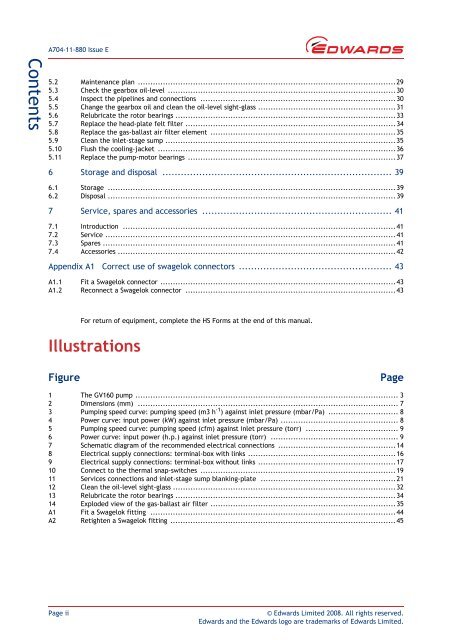
Edwards, GV160 Dry Vacuum Pumps Instruction Manual
Edwards, GV160 Dry Vacuum Pumps Instruction Manual
Edwards, GV160 Dry Vacuum Pumps Instruction Manual
Create successful ePaper yourself
Turn your PDF publications into a flip-book with our unique Google optimized e-Paper software.
A704-11-880 Issue E<br />
Contents<br />
5.2 Maintenance plan .......................................................................................................29<br />
5.3 Check the gearbox oil-level ...........................................................................................30<br />
5.4 Inspect the pipelines and connections ..............................................................................30<br />
5.5 Change the gearbox oil and clean the oil-level sight-glass .......................................................31<br />
5.6 Relubricate the rotor bearings ........................................................................................33<br />
5.7 Replace the head-plate felt filter ....................................................................................34<br />
5.8 Replace the gas-ballast air filter element ..........................................................................35<br />
5.9 Clean the inlet-stage sump ............................................................................................35<br />
5.10 Flush the cooling-jacket ...............................................................................................36<br />
5.11 Replace the pump-motor bearings ...................................................................................37<br />
6 Storage and disposal ........................................................................... 39<br />
6.1 Storage ...................................................................................................................39<br />
6.2 Disposal ................................................................................................................... 39<br />
7 Service, spares and accessories .............................................................. 41<br />
7.1 Introduction .............................................................................................................41<br />
7.2 Service .................................................................................................................... 41<br />
7.3 Spares ..................................................................................................................... 41<br />
7.4 Accessories ...............................................................................................................42<br />
Appendix A1 Correct use of swagelok connectors .................................................. 43<br />
A1.1 Fit a Swagelok connector ..............................................................................................43<br />
A1.2 Reconnect a Swagelok connector ....................................................................................43<br />
For return of equipment, complete the HS Forms at the end of this manual.<br />
Illustrations<br />
Figure<br />
Page<br />
1 The <strong>GV160</strong> pump ......................................................................................................... 3<br />
2 Dimensions (mm) ........................................................................................................ 7<br />
3 Pumping speed curve: pumping speed (m3 h -1 ) against inlet pressure (mbar/Pa) ............................ 8<br />
4 Power curve: input power (kW) against inlet pressure (mbar/Pa) ............................................... 8<br />
5 Pumping speed curve: pumping speed (cfm) against inlet pressure (torr) ..................................... 9<br />
6 Power curve: input power (h.p.) against inlet pressure (torr) ................................................... 9<br />
7 Schematic diagram of the recommended electrical connections ...............................................14<br />
8 Electrical supply connections: terminal-box with links ...........................................................16<br />
9 Electrical supply connections: terminal-box without links .......................................................17<br />
10 Connect to the thermal snap-switches ..............................................................................19<br />
11 Services connections and inlet-stage sump blanking-plate ......................................................21<br />
12 Clean the oil-level sight-glass .........................................................................................32<br />
13 Relubricate the rotor bearings ........................................................................................34<br />
14 Exploded view of the gas-ballast air filter ..........................................................................35<br />
A1 Fit a Swagelok fitting ..................................................................................................44<br />
A2 Retighten a Swagelok fitting ..........................................................................................45<br />
Page ii<br />
© <strong>Edwards</strong> Limited 2008. All rights reserved.<br />
<strong>Edwards</strong> and the <strong>Edwards</strong> logo are trademarks of <strong>Edwards</strong> Limited.


