Model 1250-XX Calibrator Kit Instruction Sheet - Sierra Monitor ...
Model 1250-XX Calibrator Kit Instruction Sheet - Sierra Monitor ...
Model 1250-XX Calibrator Kit Instruction Sheet - Sierra Monitor ...

Create successful ePaper yourself
Turn your PDF publications into a flip-book with our unique Google optimized e-Paper software.
<strong>Sierra</strong> <strong>Monitor</strong> Corporation<br />
1991 Tarob Court<br />
Milpitas, California 95035 U.S.A.<br />
Phone: 408-262-6611<br />
Toll Free: 800-727-4377<br />
FAX: 408-262-9042<br />
E-Mail: sierra@sierramonitor.com<br />
<strong>Model</strong> <strong>1250</strong>-<strong>XX</strong><br />
<strong>Calibrator</strong> <strong>Kit</strong> <strong>Instruction</strong> <strong>Sheet</strong><br />
APPLICABILITY & EFFECTIVITY<br />
This manual provides instructions for the following <strong>Sierra</strong> <strong>Monitor</strong> products:<br />
<strong>Model</strong><br />
Description<br />
<strong>1250</strong>-01 <strong>Calibrator</strong> <strong>Kit</strong>, Type A<br />
<strong>1250</strong>-02 <strong>Calibrator</strong> <strong>Kit</strong>, Type B<br />
<strong>1250</strong>-03 <strong>Calibrator</strong> <strong>Kit</strong>, Type C<br />
This manual is effective: March 1, 1997<br />
<strong>Instruction</strong> Manual Part Number: T15006
<strong>Instruction</strong> Manual<br />
<strong>Model</strong> <strong>1250</strong><br />
<strong>Calibrator</strong> <strong>Kit</strong><br />
<strong>1250</strong>-01 Type A <strong>Calibrator</strong> <strong>Kit</strong><br />
<strong>1250</strong>-02 Type B <strong>Calibrator</strong> <strong>Kit</strong><br />
<strong>1250</strong>-03 Type C <strong>Calibrator</strong> <strong>Kit</strong><br />
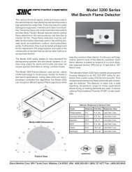
The <strong>Model</strong> <strong>1250</strong> <strong>Calibrator</strong> <strong>Kit</strong> (Fig. 1) is used to deliver<br />
calibration gas to <strong>Sierra</strong> <strong>Monitor</strong> combustible gas,<br />
oxygen deficiency and toxic gas sensor modules. Each<br />
kit consists of a regulator, calibration fitting, 3-feet of<br />
tubing and carrying case. The cylinders of calibration<br />
gas are provided separately. There are three versions<br />
of the <strong>Calibrator</strong> <strong>Kit</strong> dependent upon the specific type<br />
of regulator (see Figure 2) included in the kit. The<br />
three different regulator types are required to match<br />
the three different types of calibration gas cylinders<br />
available, depending upon the calibration gas required.<br />
While most situations will require only one type of<br />
regulator, there are cases where the user might require<br />
more than one regulator due to the use of more than<br />
one type of calibration gas cylinder. See Table 1 to<br />
determine which type of calibrator kit is required.<br />
TUBING<br />
REGULATOR<br />
CALIBRATION FITTING<br />
Figure 1<br />
<strong>Model</strong> <strong>1250</strong>-<strong>XX</strong> Calibration <strong>Kit</strong><br />
Calibration Cylinder Cylinder Regulator/<br />
Gas Part No. Capacity <strong>Kit</strong> Type<br />
Zero Grade Air 1260-00 105 liters A<br />
H 2<br />
S in Air, 25 ppm 1260-01 74 liters B<br />
Combustibles, 50% LEL 1260-02 105 liters A<br />
CO, 100 ppm 1260-04 105 liters A<br />
H 2<br />
S in N 2<br />
, 25 ppm 1260-05 57 liters A<br />
Cl 2<br />
, 5 ppm 1260-06 104 liters C<br />
H 2<br />
, 500 ppm 1260-07 105 liters A<br />
SO 2<br />
, 50 ppm 1260-10 74 liters B<br />
NO 2<br />
, 20 ppm 1260-12 74 liters B<br />
CO, 1000 ppm 1260-13 105 liters A<br />
NO, 20 ppm 1260-19 74 liters B<br />
H 2<br />
S, 10 ppm 1260-21 74 liters B<br />
ETO (C 2<br />
H 4<br />
O), 20 ppm 1260-27 74 liters B<br />
CO 2<br />
, 2000 ppm 1260-80 105 liters A<br />
(Concentrations listed are nominal)<br />
Table 1: Calibration Gas Cylinders<br />
Page:<br />
1<br />
<strong>1250</strong>-<strong>XX</strong> Calibration <strong>Kit</strong> (3/97)
<strong>Instruction</strong> Manual<br />
Procedures using Type A Regulator<br />
1. Preparation<br />
a. Remove the regulator, tubing, calibration<br />
adapter and calibration gas cylinder from the<br />
case.<br />
b. Connect the gas delivery tubing to the<br />
regulator's output port if it is not already connected.<br />
c. Connect the calibration fitting to the end of the<br />
gas sensor module.<br />
d. Connect the gas delivery tubing to the calibration<br />
fitting.<br />
e. Install the regulator on the gas cylinder.<br />
f. Check the pressure reading on the regulator's<br />
pressure gauge.<br />
NOTE: Do not use a cylinder if the pressure<br />
drops below 50 psi; get a new gas cylinder.<br />
Also, do not leave the regulator on the cylinder<br />
when not in use.<br />
2. Calibration<br />
a. Depress the flow control valve and make a 1/4<br />
turn to start the flow of gas<br />
b. Allow the gas to flow to the gas sensor module<br />
for the time specified by the module instructions.<br />
c. Calibrate the sensor module following the instructions<br />
in the sensor module instruction<br />
manual.<br />
d. Depress the flow control valve and make a 1/4<br />
turn to stop the flow of gas..<br />
e. Remove the regulator from the cylinder<br />
f. Remove the tube fitting from the calibration fitting.<br />
g. Unscrew the calibration fitting from the detector<br />
head by turning it counterclockwise.<br />
h. Return the gas cylinder, regulator, calibration<br />
fitting and tubing to the calibration kit case.<br />
Procedures using Type B or C Regulator<br />
1. Preparation<br />
a. Remove the regulator, tubing, calibration<br />
adapter and calibration gas cylinder from the<br />
case.<br />
b. Install the regulator on the gas cylinder.<br />
c. Check the pressure in the gas cylinder<br />
1) Make sure the cylinder valve is turned off.<br />
2) Make sure the valve on the regulator is<br />
closed by turning it to off position.<br />
3) Open the gas cylinder slightly by turning it<br />
counter clockwise to the on position.<br />
4) Check the pressure reading on the<br />
regulator's pressure gauge.<br />
NOTE: Do not use a cylinder if the pressure<br />
drops below 50 psi; get a new gas<br />
cylinder.<br />
5) Close the gas cylinder valve by turning it to<br />
the off position.<br />
d. Connect the gas delivery tubing to the<br />
regulator's output port if it is not already connected.<br />
e. Connect the calibration fitting to the end of the<br />
gas sensor module.<br />
f. Connect the gas delivery tubing to the calibration<br />
fitting.<br />
2. Calibration<br />
a. Open the gas flow valve on top of the sample<br />
gas cylinder by turning it counter clockwise.<br />
b. Open the gas delivery valve on the regulator<br />
by turning it clockwise.<br />
c. Allow the gas to flow to the gas sensor module<br />
for the time specified by the module instructions.<br />
d. Calibrate the sensor module following the instructions<br />
in the sensor module instruction<br />
manual.<br />
e. Close the gas delivery valve by turning it counterclockwise.<br />
f. Remove the tube fitting from the calibration fitting.<br />
g. Unscrew the calibration fitting from the detector<br />
head by turning it counterclockwise.<br />
3. Finishing the calibration<br />
a. Be sure the cylinder gas flow valve is closed.<br />
b. Remove the regulator from the sample gas cylinder.<br />
c. Return the gas cylinder, regulator, calibration<br />
fitting and tubing to the calibration kit case.<br />
<strong>1250</strong>-<strong>XX</strong> Calibration <strong>Kit</strong> (3/97)<br />
Page:<br />
2
<strong>Instruction</strong> Manual<br />
Cylinder Connection<br />
Flow Control<br />
Valve<br />
Cylinder Connection<br />
Gas Delivery Valve<br />
1256-01 Type A Regulator 1256-02 Type B Regulator 1256-03 Type C Regulator<br />
Figure 2: Regulators for <strong>Model</strong> <strong>1250</strong>-<strong>XX</strong> <strong>Calibrator</strong> <strong>Kit</strong>s<br />
Specifications for 1260 Series Gas Cylinders:<br />
Type A Gas Cylinders (Combustible Gas - LEL, CO, H 2<br />
,<br />
Air)<br />
Dimensions (cylinder):13.75 x 3.25 in. (34.9 x 8.2 cm)<br />
Weight (cylinder): 2.3 lb. (1.05 Kg)<br />
Cylinder pressure: Max 1000 psig<br />
Volume:<br />
3.6 cu. ft. (105 liters) at STP<br />
Type A Gas Cylinders (H 2<br />
S for 4101/5100-05)<br />
Dimensions (cylinder):13.5 x 3.5 in. (34.3 x 8.9 cm)<br />
Weight (cylinder): 1.8 lb. (0.8 Kg)<br />
Cylinder pressure: Max 500 psig<br />
Volume:<br />
2.0 cu. ft. (57 liters) at STP<br />
Type B Gas Cylinders (SO 2<br />
, NO 2<br />
, NO, H 2<br />
S, ETO)<br />
Dimensions (cylinder):16.25 x 4.0 in. (41.3 x 10.2 cm)<br />
Weight (cylinder): 1.75 lb. (0.8 Kg)<br />
Cylinder pressure: Max 480 psig<br />
Volume:<br />
2.6 cu. ft. (74 liters) at STP<br />
Type C Gas Cylinders (Cl 2<br />
)<br />
Dimensions (cylinder):12.25 x 3.25 in. (31.1 x 8.2 cm)<br />
Weight (cylinder): 2.2 lb. (1.0 Kg)<br />
Cylinder pressure: Max 1800 psig<br />
Volume:<br />
3.7 cu. ft. (104 liters) at STP<br />
Specifications for 1256 Series Regulators (See Figure 2):<br />
Type A Regulator - 1256-01<br />
Maximum Inlet Pressure: 1000 psig (69 bar)<br />
Weight (cylinder): 1.0 lb.<br />
Inlet Connection: C-10 (5/5" - 18 UNF)<br />
Outlet Connection: 3/16" hose barb<br />
Type B Regulator - 1256-02<br />
Maximum Inlet Pressure: 480 psig<br />
Weight (cylinder): 1.0 lb.<br />
Inlet Connection: CGA 170/ 1/8" hose barb<br />
Outlet Connection: 1/8" hose barb<br />
Type C Regulator - 1256-03<br />
Maximum Inlet Pressure: 1800 psig<br />
Weight (cylinder): 1.0 lb.<br />
Inlet Connection: CGA-180 1/8" hose barb<br />
Outlet Connection: 1/8" hose barb<br />
Spare Parts<br />
Description<br />
Part No.<br />
Carrying Case 1255-01<br />
Calibration Tubing, 36" PTFE 1255-02<br />
Calibration Adapter 5358-00<br />
LIMITED WARRANTY<br />
SIERRA MONITOR CORPORATION warrants its products<br />
to be free from defects in workmanship or material under<br />
normal use and service for two years after date of shipment.<br />
SMC will repair or replace without charge any equipment<br />
found to be defective during the warranty period. Final determination<br />
of the nature and responsibility for defective or<br />
damaged equipment will be made by SMC personnel.<br />
All warranties hereunder are contingent upon proper use in<br />
the application for which the product was intended and do<br />
not cover products which have been modified or repaired<br />
without SMC approval or which have been subjected to accident,<br />
improper maintenance, installation or application, or on<br />
which original identification marks have been removed or<br />
altered. This Limited Warranty also will not apply to interconnecting<br />
cables or wires, consumables (ie. calibration gases,<br />
batteries, sensors), nor to any damage resulting from battery<br />
leakage.<br />
In all cases SMC’s responsibility and liability under this warranty<br />
shall be limited to the cost of the equipment. The purchaser<br />
must obtain shipping instructions for the prepaid return<br />
of any item under this warranty provision and compliance<br />
with such instruction shall be a condition of this warranty.<br />
Except for the express warranty stated above, SMC disclaims<br />
all warranties with regard to the products sold hereunder<br />
including all implied warranties of merchantability and fitness<br />
and the express warranties stated herein are in lieu of all<br />
obligations or liabilities on the part of SMC for damages including,<br />
but not limited to, consequential damages arising<br />
out of/or in connection with the use or performance of the<br />
product.<br />
Page:<br />
3<br />
<strong>1250</strong>-<strong>XX</strong> Calibration <strong>Kit</strong> (3/97)