Handbook of High Speed Photography - IET Labs, Inc.
Handbook of High Speed Photography - IET Labs, Inc.
Handbook of High Speed Photography - IET Labs, Inc.

You also want an ePaper? Increase the reach of your titles
YUMPU automatically turns print PDFs into web optimized ePapers that Google loves.
TTT<br />
TTT'<br />
4M44|Ht|MHM4<br />
<<br />
Q.<br />
\<br />
X<br />
t<br />
J**.<br />
o<br />
o<br />
G<br />
<<br />
<<br />
LLI<br />
Z<br />
LU<br />
(J<br />
*H#.HANDB„°F0K «H4#<br />
<strong>High</strong>-<strong>Speed</strong><br />
r^raiTrr»Tcn?iia:r-T<br />
»»»*»•*•*•»•»»
HANDBOOK OF<br />
PHOTOGRAPHY<br />
by<br />
Charles E. Miller<br />
SECOND EDITION<br />
(Revised)<br />
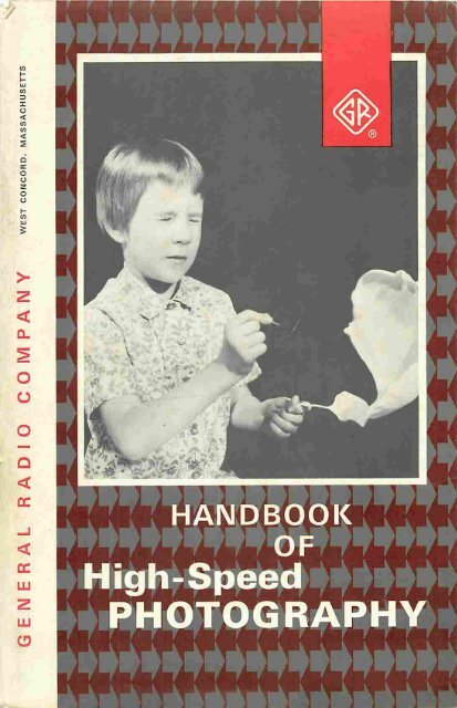
on the cover<br />
A pin struck balloon. Photo taken using a 4 x 5 camera<br />
loaded with Kodak Tri-X film. Exposure data: two 1532 Strobolumes,<br />
45-degree lighting, set back 8 feet from subject;<br />
camera set to f/11. A microphone picked up the sound <strong>of</strong> the<br />
burst and triggered the flash i n a darkened room. No syn<br />
chronization; camera shutter opened and closed manually<br />
just before and after burst.<br />
GENERAL RADIO<br />
COMPANY<br />
WEST CONCORD • MASSACHUSETTS • USA<br />
Copyright 1963 and 1967, by General Radio Company, West Concord, Mass., U.S.A.<br />
Form 3100-D<br />
Printed in U.S.A.
TABLE OF CONTENTS<br />
ACKNOWLEDGEMENT<br />
FOREWORD<br />
SECTION 1. INTRODUCTION 1<br />
1.1 Stopping Action with a Short Exposure Time 1<br />
1.2 Multiple-Exposure Motion Studies with a Strobotac meter 2<br />
1.3 Using the Stroboscope with Moving Film 8<br />
SECTION 2. CHARACTERISTICS OF STROBOSCOPES 9<br />
2.1 Introduction 9<br />
2.2 Using the Tables 9<br />
2.3 Flash Intensity Versus Duration 12<br />
2.4 Timing in <strong>High</strong>-<strong>Speed</strong> <strong>Photography</strong> 13<br />
2.5 A Specific Example 13<br />
SECTION 3. GENERAL RADIO STROBOSCOPES 16<br />
3.1 The Type 1539 Stroboslave®electronic stroboscope 16<br />
3.2 The Type 1531 Strobotac® electronic stroboscope<br />
3.3 The Type 1538 Strobotac® electronic stroboscope<br />
18<br />
21<br />
3.4 The Type 1540 Strobolume® electronic stroboscope 23<br />
SECTION 4. STILL PHOTOGRAPHY 25<br />
4.1 General 25<br />
4.2 The Output Characteristics <strong>of</strong> General Radio Stroboscopes 25<br />
4.3 Film Choice 28<br />
4.4 Guide Number Chart 30<br />
4.5 Lightin g Techniques 32<br />
4.6 Shadowgraph <strong>Photography</strong> with a Scotch lite Screen 34<br />
4.7 Ambient Light Conditions 35<br />
4.8 Operation <strong>of</strong> Camera Shutter at <strong>High</strong> <strong>Speed</strong>s 38<br />
SECTION 5. SYNCHRONIZATION 41<br />
5.1 General 41<br />
5.2 Recognizing the Event: Various Means <strong>of</strong> Triggering the<br />
Synchronization Sequence 41<br />
5.3 Processing the Trigger Signal 48<br />
5.4 Taking a Typical <strong>High</strong>-<strong>Speed</strong> Photograph 55<br />
SECTION 6. MOTION-PICTURE PHOTOGRAPHY 58<br />
6.1 Use <strong>of</strong> a Movie Camera 58<br />
6.2 Conventional Movie Cameras 58<br />
6.3 <strong>High</strong>-<strong>Speed</strong> Movie Cameras 61<br />
6.4 Movie Camera Synchronization 63<br />
6.5 Selecting a Camera 65<br />
PHOTOGRAPHS 66<br />
BIBLIOGRAPHY 81<br />
INDEX 84<br />
CATALOG SECTION 86<br />
iii<br />
iv
ACKNOWLEDGMENT<br />
SECOND EDITION<br />
Of the many people who contributed to this second<br />
edition, the author would particularly like to thank Richard<br />
A. Jokinen for his considerable editorial efforts. Dr. Harold<br />
E. Edgerton <strong>of</strong> M.I.T. has provided continuing encourage<br />
ment and assistance, as well as many <strong>of</strong> the photographic<br />
illustrations. The author would also like to thank Mr. David<br />
B. Eisendrath <strong>of</strong> NewYork City for his helpful suggestions,<br />
and the other friends and customers <strong>of</strong> General Radio who<br />
provided us with many <strong>of</strong> the interesting high-speed photos.<br />
C. E.Miller<br />
General Radio Company<br />
June, 1967
FOREWORD<br />
When I first heard about high-speed photography only a few,<br />
perhaps a dozen, were fortunate enough to use the technique.<br />
The main use was in the study <strong>of</strong> ballistics and shock waves.<br />
All <strong>of</strong> this work followed directly from the splendid research <strong>of</strong><br />
Mach more than one hundred years ago. He used spark gaps to<br />
produce light from a small volume to expose silhouette photo<br />
graphs <strong>of</strong> bullets and shock waves directly onto hand-made glass<br />
plates.<br />
The day has now arrived when high-speed photography as a<br />
research tool is commonplace. This book is to introduce high<br />
speed photography to the masses. Not only will the elaborate<br />
research laboratories <strong>of</strong> our day use the method butalmost every<br />
one will. It is symbolic that high-school students today are do<br />
ing involved experimental research that would have been con<br />
sidered very difficult only a few years ago. The tempo <strong>of</strong> our<br />
time is fulfilled. The new generation arises with skills and<br />
techniques that those <strong>of</strong> the older generation did not, or could<br />
not, exploit.<br />
The perfection <strong>of</strong> the new xenon FX-6A flash lamp by<br />
Kenneth Germeshausen and his collaborators, among whom I<br />
consider it a joy to be included, has aided in bringing the new<br />
Strobotac® electronic stroboscope to a form and performance<br />
where increased use is obtained. A paralleling development <strong>of</strong><br />
the circuits and packaging by Michael Fitzmorris and Malcolm<br />
Holtje <strong>of</strong> General Radio Company, together with the cooperation<br />
<strong>of</strong> many <strong>of</strong> the staff <strong>of</strong> that company, has resulted in the unique<br />
instrument whose use for photography is described in detail in<br />
the following pages.<br />
Developments in photography have contributed to the use <strong>of</strong><br />
the Strobotac as a practical device for high-speed photography.<br />
Of special interest is the Polaroid-Land photography system<br />
which permits the almost immediate inspection <strong>of</strong> the end result.<br />
Then another picture can be taken at once to correct a fault or<br />
to improve the photography. Not only the Polaroid system, but<br />
photography in general with its many aspects can be used in<br />
many ways with the flashes <strong>of</strong> light from the Strobotac.<br />
The advent <strong>of</strong> this book,then, marks a new era which brings<br />
the high-speed photographic system <strong>of</strong> experimental research into<br />
the reach <strong>of</strong> everyone. I foresee great results when we can "see"<br />
and "understand" the many now mysterious and unknown things<br />
that whir and buzz about us. There is still need for new tech<br />
niques and results. Let us hear from you.<br />
Harold E. Edgerton
section 1<br />
INTRODUCTION<br />
1.1 STOPPING ACTION WITH A SHORT EXPOSURE TIME.<br />
It is possible, using the fastest mechanical between-the-lens<br />
shutters or conventional phot<strong>of</strong>lash units, to obtain exposure times<br />
down to 1/1000 second. Such exposure speeds are adequate for stop<br />
ping the motion <strong>of</strong> ordinary events, such as a photo-finish at the race<br />
track or the leap <strong>of</strong> a ballet dancer, but are not fast enough to prevent<br />
blurring in photographs <strong>of</strong> extremely high-speed events. However, by<br />
using a strobe light, exposure times as small as a fraction <strong>of</strong> a micro<br />
second and intensities <strong>of</strong> millions <strong>of</strong> beam candles can be realized.<br />
Such a brilliant, extremely brief light is generated by passing an elec<br />
trical spark <strong>of</strong> several-thousand amperes through Xenon gas. The gas<br />
intensifies the spark and produces a light spectrum similar to that <strong>of</strong><br />
daylight. Figure 1-1 is a table showing the effects <strong>of</strong> exposure time<br />
on photographic blur vs subject velocity.<br />
1000-<br />
0.0000<br />
I 10 100 1000 10,000 100,000 1,000,000<br />
SUBJECT VELOCITY IN FEET PER SECOND<br />
where t = flash duration<br />
Photographic blur = 0.000012 jc subject velocity x T.<br />
Figure 1-1.<br />
Photographic blur vs velocity and exposure time.
Figure 1-2. A .22-calibre rifle bullet<br />
photographed in flight. The faint gray<br />
streak extending in front <strong>of</strong> the<br />
bullet along its path is exposure<br />
resulting from flash-larnp afterglow.<br />
A single, high-intensity flash <strong>of</strong> the<br />
Strobotac was triggered with a micro<br />
phone to stop the projectile's 1100-<br />
feet-per-second velocity. (Polaroid<br />
Type 47 film, ASA 3000, 3-microsecond<br />
exposure at f/22. The reflector<br />
was removed from the lamp.)<br />
Suppose, for example, a photograph is required <strong>of</strong> a .22-calibre<br />
rifle bullet in flight. The bullet travels about 1100 feet per second.<br />
During the 1-millisecond exposure produced by a mechanical shutter<br />
the bullet travels about 13 inches. During the 80-microsecond exposure<br />
<strong>of</strong> a high-speed movie camera, it moves about one inch, still too far<br />
for good photographic resolution. Needed for this and similar applica<br />
tions is an exposure time <strong>of</strong> a few microseconds. In 3.0 microseconds,<br />
for instance, the bullet travels only 0.04 inch (see Figure 1-2). An ex<br />
cellent example <strong>of</strong> what is possible using a single-flash <strong>of</strong> a few micro<br />
seconds duration is the series <strong>of</strong> photographs <strong>of</strong> a milk drop splashing<br />
on a hard surface shown in Figure 1-3. For other examples, refer to<br />
the photo section near the end <strong>of</strong> this book. For explanation <strong>of</strong> the<br />
methods used to produce such pictures refer to Sections 4 and 5.<br />
1.2 MULTIPLE-EXPOSURE MOTION STUDIES WITH A STROBO-<br />
TACHMETER.<br />
Often the study <strong>of</strong> the relationship between events occuring in<br />
rapid succession calls for a means <strong>of</strong> making a series <strong>of</strong> high-speed<br />
photographs in a very short time. Usually a series <strong>of</strong> single flash<br />
photographs is prohibitively difficult to obtain or will not really show<br />
what is happening. A method which is easy and which results in clear<br />
representation <strong>of</strong> many high-speed actions is the multiple-flash expo<br />
sure <strong>of</strong> a single film frame.<br />
For example, suppose an engineer wants to determine the angular<br />
velocity and acceleration <strong>of</strong> a rotating shaft so that he can calculate<br />
the transient characteristics <strong>of</strong> the load being driven by the shaft.<br />
This data would be easy to collect if the engineer had a source <strong>of</strong><br />
short-duration light flashes (short enough to stop the motion <strong>of</strong> the<br />
shaft) that would repeat at equally spaced and known time intervals.<br />
2
Figure 1-3. These jewelled crowns, which show a drop <strong>of</strong> milk splash<br />
ing on a hard surface, were made with the light <strong>of</strong> precisely timed<br />
flashes from a Strobotac® electronic stroboscope.<br />
Figure 1-4. Multiple-flash analysis <strong>of</strong> shaft rotational motion.<br />
DIRECTION OF<br />
SHAFT ROTATION<br />
An«ANGULAR DISPLACEMENT<br />
OF SHAFT AT THE<br />
INSTANT OF nTH LIGHT<br />
FLASH.<br />
Typical pattern obtained from a multiple-flash photograph <strong>of</strong> the end <strong>of</strong> a<br />
moving shaft. A single bright mark placed on the shaft's periphery re<br />
veals its position at the instant each Strobotac flash occurs.<br />
Given: Average angular velocity = 1800 rpm = 10.8° per millisecond<br />
Strobotac flash rate = 21,600 flashes per minute = 12 flashes<br />
per revolution<br />
tp =time between Strobotac flashes = 2.78 milliseconds<br />
Camera shutter speed approximately 1/30 second<br />
To determine the shaft's average angular velocity at different positions,<br />
measure the angles between adjacent mark positions on the photograph<br />
and divide by tp. Consider this average value over each displacement<br />
interval as the approximate angular velocity at the midpoint <strong>of</strong> the inter<br />
val. Since this example is symmetrical, only half <strong>of</strong> the calculations<br />
need be made. For example:<br />
Angles<br />
Measured<br />
From<br />
Photograph<br />
Average<br />
Angular Velocity<br />
In Degrees<br />
Per Millisecond<br />
(Angle/tp)<br />
Shaft<br />
Displacement<br />
At Midpoint<br />
Of Interval<br />
A,, (360-An) = 21° ^1,0=7.55 10°, 350°<br />
(A2"Al)> (AirAio) = 24° w2,l =8-63 33°, 327°<br />
(A3-A2), (A10-A9) = 28° W3?2= 10.1 59°, 301°<br />
(A4-A3), (A9-A8) = 32° W4)3=ll.5 89°, 271°<br />
(A5-A4), (A8-A7) = 36° W5?4 = 12.9 123°, 237°<br />
(A6-A5), (A7-A6) = 39° W6>5 = 14.0 160°, 200°
Figure 1-4 (Continued)<br />
Angular acceleration may be computed in a similar fashion from these<br />
angular velocity data points, e.g.:<br />
Angular<br />
Acceleration<br />
(Degrees Per<br />
Millisecond2^<br />
Shaft<br />
Displacement<br />
Midway<br />
Between<br />
Data Points<br />
/'p "<br />
0 0°<br />
(w2,i-wi,o>AP - 0.39 22°<br />
(w3>2-w2jl)/tp = 0.53 46°<br />
0.50 74°<br />
/tp =<br />
(w5)4-w4>3)/tp = 0.50 106°<br />
^6,5^5,4)/^ =<br />
0.40 142°<br />
(w7)6-w6>5)/tp = 0 180°<br />
(W8,7-W7,6)AP = -0.40 218° etc.<br />
60 120 180 240 300 360<br />
SHAFT DISPLACEMENT IN DEGREES (A) *•
From the measured distance between successive positions <strong>of</strong> a fixed<br />
point on the shaft in a multiple exposure taken with such a light<br />
source, he could calculate the instantaneous velocity and acceleration<br />
<strong>of</strong> the shaft. Details <strong>of</strong> a sample problem and corresponding calcula<br />
tions are shown in Figure 1-4. For a description <strong>of</strong> the method used<br />
to take a multiple-flash picture, refer to paragraph 5-3-3-<br />
An instrument capable <strong>of</strong> producing the flashes described is a<br />
stroboscope or a strobotachometer. Such equipment has been available<br />
commercially for many years, and is standard equipment for visual mo<br />
tion analysis in many industries that use machinery with rapidly moving<br />
parts. The stroboscope also has many applications in science and ed<br />
ucation, sports and advertising. Multiple-exposure pictures <strong>of</strong> the ba<br />
sic motions <strong>of</strong> various athletic feats, such as the swing <strong>of</strong> a golf club<br />
or the release <strong>of</strong> an arrow from a bow, have proven to be most instruc<br />
tive. Some noteworthy examples <strong>of</strong> this technique may be seen in the<br />
book Flash! Seeing the Unseen by Ultra <strong>High</strong>-<strong>Speed</strong> <strong>Photography</strong> by<br />
Edgerton and KilHan (refer to Bibliography). Multiple-flash exposures<br />
have also proven their worth to advertisers who have used them to lend<br />
eye-catching appeal to illustrations that would otherwise have been<br />
run-<strong>of</strong>-the-mill. An example <strong>of</strong> this technique is shown in Figure 1-5.<br />
(Photograph courtesy o{ Daymarc Corporation, Waltham, Massachusetts)<br />
Figure 1-5. Multiflash photograph <strong>of</strong> a semiconductor diode being at<br />
tracted to a magnetic Daymarc Diode Clip.
Figure 1-6-<br />
Dynamic redistribution <strong>of</strong> stress in a rock model<br />
undergoing fracture<br />
D 1<br />
^^vi^B<br />
-•* ' I<br />
/% wi eM<br />
(Photographs courtesy <strong>of</strong> E. Hoek, National Mechanical Engineering Research Institute,<br />
Pretoria, South Africa.)<br />
A series <strong>of</strong> multiple-flash, movingfilm,<br />
high-speed photographs taken<br />
REFLECTIVE CEMENT LAYER<br />
with the Strobotac electronic strobo<br />
PHOTO-ELASTIC LAYER<br />
scope to show the dynamic redistri<br />
CIRCULAR POLARIZERS<br />
bution <strong>of</strong> stress in a rock model un- srR0<br />
MONOCHROMATIC FILTER<br />
dergoing fracture. The model is a 5-<br />
- CAMERA<br />
inch-square rock plate, '4-inch thick,<br />
with a M-inch-diameter circular hole<br />
in the center. It was subjected to<br />
vertical stresses ranging from 33,000 Ib/sq in. in (a) to 40,000 Ib/sq in. in (e)<br />
and (f). The lateral stress was held at 0.15 the value <strong>of</strong> the vertical stress.<br />
The strain patterns were photographed by the birefringent layer technique in<br />
which a layer <strong>of</strong> photo-elastic plastic is bonded onto the surface <strong>of</strong> the model<br />
with a reflective cement. The photo-elastic pattern induced in the layer by strain<br />
in the model is then analyzed with reflected polarized light. The monochromatic<br />
filter shown in the diagram was a Wratten 77, which passes light <strong>of</strong> 5461 ang<br />
strom units.<br />
These photographs were taken on llford HP3 35-mm film (ASA 160) with a Leica<br />
Summicron 50-mm lens set at f/2. The Strobotac was set at 300 flashes per minute<br />
(3-microsecond exposure), and the film was transported past the lens at 5 inches<br />
per second with an oscillograph camera. No shutter was used. Both the camera<br />
and the Strobotac were approximately three feet from the subject, as shown in<br />
the sketch.<br />
ROCK<br />
MODEL
1.3 USING THE STROBOSCOPE WITH MOVING FILM.<br />
It is impossible to study some complex motions using the multi<br />
ple-exposure technique. This is especially so when the motion is con<br />
fined to a small area or is characterized by a change <strong>of</strong> shape rather<br />
than a translational motion, that is, the subject does not "get out <strong>of</strong><br />
its own way" to permit the photographing <strong>of</strong> separate and discreet suc<br />
cessive images. For example, the changing stress patterns in a sample<br />
<strong>of</strong> material (see Figure 1-6). Studies <strong>of</strong> this type can be made by means<br />
<strong>of</strong> a high-speed motion picture camera, such as the Hycam, Fastax,<br />
etc., and a stroboscope. These cameras can move film past the camera<br />
lens at a high rate <strong>of</strong> speed so that thousands <strong>of</strong> frames per second can<br />
be exposed. The series <strong>of</strong> pictures produced by this method will dis<br />
play successive phases <strong>of</strong> a single cycle <strong>of</strong> the studied motion.<br />
The stroboscope is also a very useful light source for use with<br />
high-speed movie cameras. The short duration flash <strong>of</strong> the stroboscope<br />
stops motion that would normally be blurred even when photographed by<br />
the fastest <strong>of</strong> movie cameras, as would the motion <strong>of</strong> a high-speed pro<br />
jectile. This improvement is especially advantageous where frame-byframe<br />
analysis <strong>of</strong> the film must be made. For a more detailed descrip<br />
tion <strong>of</strong> the use <strong>of</strong> a stroboscopic light sources with moving-film devices,<br />
refer to Section 6.<br />
The stroboscope can also be used to advantage in photographing<br />
heat-sensitive subjects, e.g., biological specimens. The stroboscope,<br />
due to its extremely low duty cycle or "on" time, is a relatively cool<br />
source <strong>of</strong> light.
section 2<br />
CHARACTERISTICS<br />
OF STROBOSCOPES<br />
2.1 INTRODUCTION<br />
Several different types <strong>of</strong> stroboscopic light sources representing<br />
a wide range <strong>of</strong> characteristics and a wide range <strong>of</strong> prices are availa<br />
ble to the high-speed photographer. The principal specified character<br />
istics <strong>of</strong> a stroboscope are: flash duration, repetition frequency, and<br />
light output. Other considerations are: means <strong>of</strong> triggering, type <strong>of</strong><br />
trigger delay available, power required, physical dimensions (as they<br />
affect portability), and economy. The type <strong>of</strong> stroboscope a photogra<br />
pher chooses naturally depends on the type <strong>of</strong> picture he wants to take.<br />
In order to aid him in making this choice, the following paragraphs, in<br />
conjunction with Tables 2-1 and 2-2, indicate which type <strong>of</strong> strobo<br />
scope is best suited for each <strong>of</strong> various categories <strong>of</strong> high-speed<br />
photography.<br />
2.2 USING THE TABLES.<br />
Table 2-1 lists the desirable characteristics <strong>of</strong> light sources<br />
corresponding to many applications <strong>of</strong> the stroboscope in high-speed<br />
photography. All values given in the table are approximate; exact<br />
light requirements depend on the individual picture-taking situation.<br />
In many cases, the values listed can be exceeded; that is, a faster,<br />
brighter, more expensive light source than called for can be used, so<br />
that the instrument obtained for the toughest job will do the lesser<br />
ones as well. This is not true under all circumstances, however, as<br />
the faster, more complicated instruments are more highly specialized.<br />
For example, the EG&G Type 2307 Double Flash Light Source is spe<br />
cifically designed for one application ~ measureing velocities — and<br />
its use is not practical for any other purpose.
TYPE OF APPLICATION<br />
REQUIREMENTS<br />
Single Flash<br />
Flash<br />
Duration<br />
Flashes<br />
per sec<br />
Relotive<br />
Intensity<br />
Trigger<br />
Delay*<br />
(Time)<br />
Method<br />
Illumination for portraits<br />
and other non high-speed<br />
photography (people and<br />
other slow objects)<br />
<strong>High</strong>-speed photography<br />
(birds' wings, breaking<br />
light bulbs)<br />
Ultra-high-speed<br />
photography (bullets in<br />
flight, shock-waves,<br />
high-speed machinery)<br />
Multiple Flash<br />
1/1000 s<br />
(1 ms)<br />
10-100/is<br />
<strong>High</strong><br />
Medium<br />
to <strong>High</strong><br />
1 /JLS Low to<br />
Medium<br />
Manual or<br />
Sync'd to<br />
camera (open<br />
or close switch)<br />
Manual or Sync'd to<br />
event by electrical,<br />
acoustical, optical or<br />
mechanical means<br />
Electronically<br />
sync'd to event<br />
by signal from<br />
microphone,<br />
photocell, etc.<br />
(1/25 s)<br />
Visual<br />
Electronic<br />
if any<br />
(1-100 ms)<br />
Electronic<br />
"Untimed" multiple<br />
exposure (sports,<br />
advertising, educational<br />
demonstrations) where<br />
precise timing<br />
unnecessary<br />
Precision measurements,<br />
Single frame<br />
<strong>High</strong>-speed<br />
Ultra-high speed<br />
100 /is 100 <strong>High</strong> Internal oscil<br />
lator, electronic<br />
signal from<br />
contactor, photo<br />
electric pickup,<br />
1-10 //s<br />
1 fis<br />
500<br />
1000<br />
Low to<br />
Medium<br />
etc.<br />
Pulses from<br />
calibrated<br />
internal oscillator,<br />
contactor, or other<br />
externally generated<br />
signal<br />
Visual<br />
Electronic<br />
Moving film, flashes<br />
not synchronized<br />
Moving film, flashes<br />
synchronized with camera<br />
1-100 /xs 400 Medium<br />
to <strong>High</strong><br />
1-100 /is 400 Medium<br />
to <strong>High</strong><br />
Pulses from<br />
oscillator or<br />
contactor<br />
Closed switch<br />
Precision motion studies<br />
(explosions, projectiles,<br />
vibrations)<br />
1-10 /is 100<br />
1000<br />
Low to<br />
Medium<br />
Calibrated<br />
oscillator<br />
'Refers to the delay between the input signal and the firing <strong>of</strong> the flash: thus, visual delay<br />
means that the delay between the occurance <strong>of</strong> the event and the flash depends on the photograph.<br />
TABLE 2-1.<br />
Table 2-2 lists the characteristics <strong>of</strong> several commercially avail<br />
able stroboscopes in a form that facilitates comparison <strong>of</strong> these charac<br />
teristics with those required in Table 2-1. The reader may notice that<br />
there is no strobe in the tables that satisfactorily answers the need for<br />
10
Light Source<br />
GR Type 1539<br />
Scroboslave0<br />
electronic<br />
a <strong>of</strong> Various :eaturos <strong>of</strong> Soma General-Purpose Stroboscopes<br />
»"*<br />
Approximate<br />
Price<br />
Duration<br />
Mo« Repetition<br />
Froq flushes/sec<br />
Eneroy/flush<br />
Joules or<br />
Watt-seconds<br />
Light (million<br />
bean candclas)<br />
Time.Delay<br />
.230 0.8 to 3.0 600 io 800 0.6-18 0.48 to 33 external only<br />
100 ms 10 1 a,<br />
uncaltbratcd, with<br />
Type I531-P2<br />
GR Type 1531<br />
Sitobot«c°electroatc<br />
stroboscope<br />
GR Type 15$8<br />
Scfobot ac°eIcctroaic<br />
stroboscope<br />
1345 0.8 to 3.0 600 to 800<br />
J545 0.5 lo 3.0<br />
(8.0 with<br />
1538-P4)<br />
(has internal<br />
oscillat<strong>of</strong> for up to<br />
400 (/. calibrated)<br />
(has internal<br />
oscillator for up to<br />
3000 f/s calibrated)<br />
0.6 to IB 0.48 to 33 external only<br />
100 lis to 1 a,<br />
0.1 lo 18<br />
(44 with<br />
I5S8-P4)<br />
0.8 to 45<br />
(352 -ith<br />
Type I538-P4<br />
Capacitor)<br />
uncalibratcd, with<br />
Type 1531-P2<br />
external only<br />
100 /us to 1 s,<br />
uncalibratcd, with<br />
Type 1531-P2<br />
GR Type 1540<br />
Strobolume<br />
electronic<br />
stroboscope<br />
1775<br />
1975<br />
10 lo 15 600 io 600<br />
(400 f/s calibrated)<br />
0.25<br />
10<br />
0.47 to 16.7 100 ms to 1 s,<br />
uncalibratcd,<br />
with 1540-P4<br />
EG&G Model 553<br />
Mulri Flash Strobe<br />
11760 25<br />
40<br />
120 cpa<br />
in bursts<br />
to 1.5s<br />
6<br />
12<br />
150-400beps*<br />
external only<br />
EG&G Model 549<br />
Microtias!.<br />
$1250 0.5 0.2 6.5 50 adjustable,<br />
uncalibratcd.<br />
EG&G Model 502<br />
Multiple Micr<strong>of</strong>lash<br />
Unit<br />
15700 a<br />
JSOOlP"'l»«h<br />
1 25 • 100,000<br />
in bursts <strong>of</strong> up to<br />
20 flashes (has<br />
internal oscillator)<br />
1.5 0.2 between flashes<br />
adjuscablc 10 -<br />
40 fis<br />
RG>ype 501<br />
Mtgh-Spccd<br />
Stroboscope<br />
For 0.01 ,uF<br />
capacitor in input<br />
For 0.04 mF<br />
cspacitor in input<br />
circuit<br />
«535<br />
1.2<br />
2.1<br />
6000 ia bursts <strong>of</strong><br />
up to 0.8 a<br />
800 in burata <strong>of</strong> up<br />
to 1.5 a<br />
0.3<br />
1.3<br />
0.16<br />
0.84<br />
external only<br />
(haa internal oac.)<br />
Note: The Type 1538Suoboiac is complciety portable,aa it haa a battery-powered option. The Type 1531and Type 1539arc portable<br />
but require a power cord.<br />
The Type 1540 canbe carried, butis mainly a studiolightsource. The Type 1531-P2 Flash Delay canbeusedwitha Type<br />
1536 Photoelectric Pick<strong>of</strong>f for optical triggering.<br />
* Depending on beam angle.<br />
TABLE 2-2.<br />
a single-flash light source for photography <strong>of</strong> "people and other slow<br />
objects." This is because what is needed in this case is not really a<br />
stroboscope, but a speedlight, an essentially single-flash instrument<br />
used mainly for nontechnical photographic work. For information on<br />
this type <strong>of</strong> instrument, consult the KODAK Reference <strong>Handbook</strong> (refer<br />
to Bibliography). Most <strong>of</strong> the stroboscopes in Table 2-2 are designed<br />
for precise industrial and scientific high-speed photography, although<br />
the GR Type 1539 Stroboslave, which is small, lightweight, conve<br />
niently triggered, and inexpensive, may prove to be just the thing for<br />
the photographer who wants more speed (shorter flash durations) and<br />
higher repetition frequencies than a speedlight can give.<br />
11
2.3 FLASH INTENSITY VERSUS DURATION.<br />
The photographer may have to compromise when choosing an in<br />
strument for very high-speed applications since, as a glance at Table<br />
2-2 will prove, the greater the intensity <strong>of</strong> an instrument's flash, the<br />
longer the duration and, the lower the flash frequency rate. For exam<br />
ple, the EG&G Model 549 Micr<strong>of</strong>lash has a high-intensity submicrosecond<br />
flash, and this is at the expense <strong>of</strong> repetition frequency. About<br />
fifty times faster, but with one fifth the intensity and six times the du<br />
ration, are the flashes <strong>of</strong> the General Radio Type 1531 and Type 1538<br />
Strobotac electronic stroboscopes. A number <strong>of</strong> these instruments<br />
may be flashed in succession if a burst <strong>of</strong> high-intensity flashes with<br />
high repetition frequency is required. (Refer to paragraph 5.3.3). Fig<br />
ure 2-1 is a picture taken with such an arrangement. If light intensity,<br />
not speed, is the main concern, the General Radio Strobolume is prob<br />
ably the best choice.<br />
Figure 2-1. Unretouched photo <strong>of</strong> bullet breaking string shows how little<br />
even this fast-moving projectile travels during strobe flash. (Photo is<br />
multiple exposure, each image <strong>of</strong> the bullet corresponding to a different<br />
Strobotac flash, with a delay <strong>of</strong> approximately 50/-isec between each<br />
flash). See Figure 5-13.<br />
12
2.4 TIMING IN HIGH-SPEED PHOTOGRAPHY.<br />
The rapidity with which some events occur makes it not only im<br />
possible to "stop" the event with an ordinary flash bulb or camera shut<br />
ter but also impossible to trip the shutter and flash the light at the<br />
proper moment. What is needed is a device that will automatically set<br />
<strong>of</strong>f the flash just as the subject is in the desired position or as the ac<br />
tion is in its proper phase for the picture. There are many ways <strong>of</strong> ar<br />
ranging such a device, several <strong>of</strong> which are discussed in Section 5.<br />
Essentially, automatic triggering requires (1) a sensor, which will inter<br />
act with the subject and produce a signal — mechanical or electrical—<br />
that can be used to trigger the flash (and sometimes to trip the camera<br />
shutter), and (2) a means <strong>of</strong> adjusting the sensor or the signal it pro<br />
duces so that the arrival <strong>of</strong> the triggering impulse corresponds with the<br />
correct position <strong>of</strong> the subject. To photograph a bullet, a photographer<br />
can use a microphone as the sensor. The sound or shock waves caused<br />
by the firing <strong>of</strong> the bullet, acting on the microphone, produces an elec<br />
trical impulse that fires the flash. The means <strong>of</strong> synchronizing the<br />
flash with the bullet's position can be either the variation <strong>of</strong> the posi<br />
tion <strong>of</strong> the microphone or a variable electrical delay between the pro<br />
duction <strong>of</strong> the impulse at the microphone and the arrival <strong>of</strong> the trigger<br />
signal at the stroboscope.<br />
2.5 A SPECIFIC EXAMPLE<br />
Assume a study <strong>of</strong> thread motion in a high-speed sewing machine<br />
is to be made. What type <strong>of</strong> stroboscope is best suited for the job?<br />
The machine speed is 5000 stitches per minute; hook speed is 10,000<br />
rpm. A flash duration <strong>of</strong> 10 microseconds will be sufficient to stop the<br />
motion <strong>of</strong> the hook (assuming the hook has a relatively small diameter).<br />
Since the area to be photographed is small, the camera and light can be<br />
placed close to the subject. Hence, a relatively low intensity flash is<br />
sufficient. In order to stop the machine's action at any desired point,<br />
it is necessary to have a trigger signal synchronized with the motion <strong>of</strong><br />
the machine and a time delay for varying the relative phase between<br />
trigger signal and motion.<br />
Consulting Table 2-2, we see that the GR Type 1531, the GR<br />
Type 1538, and the GR Type 1539 meet the specifications for flash<br />
duration, repetition rate, and intensity, and that the 1531-P2 Flash De<br />
lay Unit along with the 1536 Photoelectric Pickup may be used with<br />
any one <strong>of</strong> these instruments to trigger the flash in the desired manner.<br />
13
..«""*&&.<br />
1<br />
A<br />
Figure 2-2.<br />
Study <strong>of</strong> thread behavior in high-speed sewing machine. Machine speed is 5000<br />
stitches per minute; hook speed is 10,000rpm. Photograph above shows Linh<strong>of</strong>f<br />
with Polaroid film, Strobotac with attached Flash Delay, and sewing machine<br />
(base is cut away to expose parts). Photograph at lower left shows hook action<br />
on thread at a specific phase selected by the Flash Delay. Photograph at lower<br />
right is taken from a higher angle to show the stitch-forming action just under<br />
the sewing surface. Courtesy <strong>of</strong> The Singer Company.<br />
14
The selection <strong>of</strong> one <strong>of</strong> these instruments depends on economic con<br />
siderations and on what other uses, if any, the strobe is to be put. The<br />
1539 Stroboslave, lacking an internal oscillator, would not be chosen<br />
if it is desirable to have the light flash at rates other than that <strong>of</strong> the<br />
sewing machine.<br />
The use <strong>of</strong> a frequency close to that <strong>of</strong> the object being viewed<br />
is a technique commonly employed to produce the optical illusion <strong>of</strong><br />
slow motion. If the flashing rate is slightly higher than the speed <strong>of</strong><br />
the device being observed, the device will be illuminated at succes<br />
sively earlier points in its cycle and will thus appear to move slowly<br />
backwards. Similarly, a flashing rate slightly lower than the device<br />
speed will produce the effect <strong>of</strong> apparent forward slow motion. For<br />
such an application, the 1531 and the 1538, having internal oscillators,<br />
are recommended.<br />
The Type 1538-A might be perferred if it is to be used for suc<br />
cessive machine-to-machine inspections since it can be battery pow<br />
ered and is completely portable. For aid in choosing the right instru<br />
ment, the following section describing the General Radio line <strong>of</strong> stro<br />
boscopes and related equipment has been included.<br />
TABLE 2-3<br />
TRIGGERING REQUIREMENTS<br />
FOR GENERAL RADIO STROBOSCOPES<br />
Type 1531<br />
STROBOTAC<br />
Type 1538<br />
STROBOTAC<br />
Type 1539<br />
STROBOSLAVE<br />
with 1540-P1<br />
Type 1540<br />
STROBOLUME<br />
with 1540-P3 with 1540-P4<br />
Make-Break<br />
Contacts<br />
Flrea on con<br />
tact opening<br />
Fires on con<br />
tact closing<br />
Fires on con<br />
tact closing<br />
Fire on con<br />
tact closing<br />
Fire on con<br />
tact closing<br />
Selectable; will<br />
fire on either<br />
closing or<br />
opening<br />
Photoelectric<br />
Plck<strong>of</strong>f<br />
1536 +1531-P2 1536+1531-P2<br />
or 1537<br />
1536+ 1531-P2<br />
or 1537<br />
1537 1537 1536 or 1537<br />
Electrical<br />
Signal<br />
Pos pulse: 6 V<br />
Sine wave: 2 V<br />
rma § 5 c/s<br />
or higher<br />
Pos pulse:<br />
Sine wave:<br />
0.35 V rma<br />
§ 100 c/a<br />
or higher;<br />
3.5 V rms<br />
0 5 c/a<br />
1 V<br />
Pos pulse: 2 V Pos pulse: 1 V Poa pulse: 1 V Pos pulse: 1 V<br />
Sine Wave:<br />
0.35 V rma /rom<br />
100 to 400 c/a,<br />
<strong>Inc</strong>reasing to 3.5<br />
V rms @ S c/a<br />
15
section 3<br />
GENERAL RADIO<br />
STROBOSCOPES<br />
3.1 THE TYPE 1539STROBOSLAVE® ELECTRONIC STROBOSCOPE.<br />
3.1.1 GENERAL DESCRIPTION. The Type 1539 Stroboslave (Figure<br />
3-1) is a miniature electronic stroboscope. The Stroboslave satisfies<br />
the basic requirements for motion studies and high-speed photography,<br />
but is not suitable for tachometry as it has no internal oscillator. Its<br />
reflector-lamp assembly is connected to the case by a five-foot exten<br />
sion cable so that the lamp can be used either attached to the case or<br />
conveniently positioned over the subject, even in cramped spaces. The<br />
reflector can be removed so that the strobotron lamp assembly can be<br />
inserted through a hole as small as one inch in diameter to observe ob<br />
jects in otherwise inaccessible areas (see Figure 3-2). When the re<br />
flector is in place, the light output is concentrated into a long-throw<br />
10-degree beam (measured at one-half-peak-intensity points) with an<br />
apparent source 18 inches behind the reflector front. For further, more<br />
specific information on the photographic characteristics <strong>of</strong> the 1539 as<br />
a light source with and without reflector, refer to Section 4. The Stro<br />
boslave has the same high maximum flash repetition rate, short flash<br />
duration, and the same light characteristics as the 1531 and 1538 Stro<br />
botac electronic stroboscopes.<br />
3.1.2 TRIGGERING THE STROBOSLAVE. The Stroboslave can be<br />
triggered by the closure <strong>of</strong> a switch across its input terminals or by a<br />
positive voltage pulse <strong>of</strong> at least 2 volts peak amplitude. The Strobo<br />
slave can therefore be triggered by the output pulse <strong>of</strong> the 1538 Strobo<br />
tac, the 1531 Strobotac through a 1531-P4 Trigger Cable, the 1531^P2<br />
Flash Delay, or by the 1537 Photoelectric Pickup. (A table showing<br />
all possible interconnections <strong>of</strong> the various General Radio Stroboscopic<br />
instruments is given in Section 5.) This multiplicity <strong>of</strong> trigger possibil<br />
ities, along with its small size and low cost, make the Stroboslave a<br />
most convenient and economical instrument for a variety <strong>of</strong> applications.<br />
16
Figure 3-1. The 1539-A Stroboslave.<br />
3.1.3 USES OF THE STROBOSLAVE. In some applications it is de<br />
sirable to light the subject from more than one side in order to obtain<br />
greater depth and detail in the photograph. One or two Stroboslaves<br />
can be used in this case to produce modeling illumination in arrange<br />
ments similar to those used in multiple photo-flood lighting. The Stro<br />
boslaves are triggered by one Strobotac if a particular flash repetition<br />
rate is needed; otherwise they can be triggered by the same external<br />
signal synchronized to the subject.<br />
In photographing high-speed machinery where the subject is mov<br />
ing in some constant cyclical manner, the combination <strong>of</strong> the Strobo<br />
slave and the 1537 Photoelectric Pick<strong>of</strong>f is the most convenient and<br />
economical light source available, (refer to paragraph 5-2.3 for a de<br />
scription <strong>of</strong> the 1537).<br />
17
Figure 3-2.<br />
Using the Stroboslave to illuminate the interior <strong>of</strong> a metal<br />
stencil imprinter.<br />
3.2 THE TYPE 1531 STROBOTAC® ELECTRONIC STROBOSCOPE.<br />
3.2.1 GENERAL DESCRIPTION. The Type 1531 Strobotac electronic<br />
stroboscope (Figure 3-3) is a versatile, inexpensive, high-speed light<br />
source designed to fill a wide variety <strong>of</strong> both photographic and nonphotographic<br />
needs in science and industry. Its light weight and com<br />
pact design make it convenient to use, and its light output is suitable<br />
for taking many different types <strong>of</strong> photographs. (Refer to Section 4). A<br />
self-contained electronic oscillator enables the unit to operate indepen<br />
dently at flash rates from 110 to 25,000 flashes per minute. The flash<br />
rate is continuously adjustable throughout this range, and it can be ac<br />
curately set (±1%) by means <strong>of</strong> the large calibrated dial on the instru<br />
ment panel.<br />
The Strobotac is housed in a carrying case whose cover doubles<br />
as an adjustable stand (see Figure 3-3), and protects the instrument<br />
from damage while in transit. The unit can be easily carried to any<br />
location. Power requirements are flexible. Either 120- or 240-volt ac,<br />
50- to 60- or 400-cycle power is satisfactory; maximum input power is<br />
35 watts.<br />
18
Figure 3-3.<br />
The 1531 STROBOTAC®electronic stroboscope - versatile<br />
light source for both high-speed photography and visual stroboscopy.<br />
Photographers particularly appreciate the ease with which the<br />
the lamp reflector can be positioned. The long-throw light beam can<br />
be rotated through 360° horizontally and 180° vertically without move<br />
ment <strong>of</strong> the instrument case, and the reflector can be quickly and<br />
easily removed from the flash-lamp mount when it is desired to illumi<br />
nate hard-to-reach areas. When the reflector is in place, the light out<br />
put is concentrated into a long-throw 10° beam (measured at one-halfpeak-intensity<br />
points) with an apparent source 18 inches behind the<br />
reflector front. For further, more specific, information on the photo<br />
graphic characteristics <strong>of</strong> the 1531-A as a light source both with and<br />
without reflector, refer to Section 4.<br />
19
3.2.2 EXTERNAL TRIGGERING. The Strobotac can be triggered by<br />
a wide variety <strong>of</strong> externally produced signals. An electrical signal <strong>of</strong><br />
at least 6 volts peak-to-peak amplitude can be used, but a simple con<br />
tact "make" or "break" is satisfactory. With the Strobotac range switch<br />
set on EXT INPUT, LOW INTENSITY, the repetition rate <strong>of</strong> the instru<br />
ment can be extended by the use <strong>of</strong> an external pulse source, beyond<br />
its internal, calibrated range to 600 to 800 flashes per second, and<br />
rates as high as 1000 per second are sometimes possible, depending<br />
on the condition <strong>of</strong> the Strobotron flash lamp.<br />
With the RPM dial rotated fully clockwise, the Strobotac triggers<br />
with either a positive-going electrical signal or by the opening <strong>of</strong> a<br />
set <strong>of</strong> contacts connected to the INPUT jack. In either case, the light<br />
flash follows the trigger signal with only a few microseconds delay.<br />
In practically all instances this small delay introduces no difficulties,<br />
and the light flash can be considered instantaneous.<br />
If only a negative pulse or contact closure is available for trig<br />
gering, slight modifications must be made in the triggering connection.<br />
For triggering on the leading edge <strong>of</strong> a negative electrical pulse, a<br />
General Radio Transformer Cable, Type 1532-P2B, should be used to<br />
reverse its polarity. The oversize plug on one end <strong>of</strong> this cable is<br />
plugged into the Strobotac INPUT jack, and the normal phone plug on<br />
the other end is connected to the pulse source. The RPM dial is then<br />
set fully clockwise as for positive-pulse triggering. Practically any<br />
pulse transformer may also be used instead <strong>of</strong> the 1531-P2B Cable to<br />
perform the same function.<br />
A contact closure can be made to trigger the Strobotac with mini<br />
mum delay by the simple inverting circuit diagrammed in Figure 5-10.<br />
The necessary parts can be purchased at any radio or electronics parts<br />
supply house for less than $2.00, and only a few minutes are required<br />
to assemble them. Contacts in camera shutters equipped for "X" syn<br />
chronization normally operate satisfactorily with this circuit, but some<br />
difficulty may be experienced if the contacts "bounce" when closing.<br />
(The Strobotron will fire each time electrical contact is made.) A<br />
small capacitor (approximately 0.01 micr<strong>of</strong>arad) connected across the<br />
contact terminals usually solves this problem.<br />
The 1531-P2 Flash Delay contains special circuitry to provide<br />
the same pulse-inverting function described above, so with this unit<br />
minimum triggering can also be accomplished directly from a contact<br />
closure.<br />
20
3.3 THE TYPE 1538 STROBOTAC® ELECTRONIC STROBOSCOPE.<br />
3.3.1 GENERAL DESCRIPTION. The 1538 (Figure 3-4) is an elec<br />
tronic stroboscope that combines several new, formerly unobtainable,<br />
features in a lightweight, moderately priced instrument. Although the<br />
appearance and general design are similar to those used in the 1531<br />
Strobotac, the 1538 is capable <strong>of</strong> a flashing rate six times as high —up<br />
to 150,000 flashes per minute, and its frequency stability is much bet<br />
ter than that <strong>of</strong> the 1531. The 1538 stroboscope has the additional<br />
features <strong>of</strong> either ac or dc operation (supplied by an accessory battery<br />
pack), an accessory remote lamp unit to illuminate in close quarters,<br />
and an accessory large capacitor to produce high-intensity flashes for<br />
single-flash photography. When the reflector <strong>of</strong> the 1538 is in place,<br />
the light output is concentrated into a long-throw 10-degree beam (mea<br />
sured at one-half-peak-intensity points) with an apparent source 18<br />
inches behind the reflector front. In addition, the 1538 employs solidstate<br />
circuits for zero warm-up time, so that the instrument may con<br />
veniently be turned <strong>of</strong>f when not actually in use.<br />
Figure 3-4. Type 1538-A Strobotac electronic stroboscope shown with<br />
accessories: 1538-P2 Extension Lamp; 1538-P3 Battery and Charger<br />
for portable operation; and the 1538-P4 Energy Storage Capacitor (shown<br />
mounted on the base <strong>of</strong> the 1538-A).<br />
21
The flashing rate <strong>of</strong> the 1538 Strobotac is controlled by an inter<br />
nal generator and is adjustable from 110 to 150,000 flashes per minute.<br />
This overall range is divided into four direct-reading ranges on the<br />
large, illuminated range-control knob. The first three ranges are the<br />
same as those <strong>of</strong> the 1531, and the fourth covers from 24,000 to 150,000<br />
flashes per minute, calibrated. A fifth position on the range switch<br />
provides for calibration. To avoid reading errors, only the range in use<br />
is illuminated. A larger-diameter flashing-rate control, concentric with<br />
the range knob, provides precise setting <strong>of</strong> the flashing rate. With the<br />
exception <strong>of</strong> the higher flashing rates and the 44-million-beam-candle,<br />
8-microsecond single-flash available when using its accessory 1538-P4<br />
Capacitor, the light characteristics <strong>of</strong> the 1538 Strobotac are the same<br />
as those <strong>of</strong> the 1531. For further, more specific information on the<br />
photographic characteristics <strong>of</strong> the 1538 as a light source with and<br />
without reflector, refer to Section 4.<br />
3.3.2 EXTERNAL TRIGGERING. The flash can be triggered exter<br />
nally by a simple contact closure across the input terminals, by a<br />
positive pulse (1-volt peak), or by a sine wave (0.35 volt rms). With a<br />
photoelectric pick<strong>of</strong>f (refer to Section 5), the flash can be triggered by<br />
pulses that are synchronized with a mechanical motion. With the com<br />
bination <strong>of</strong> the 1531-P2 Flash Delay and the 1536 Photoelectric Pick<strong>of</strong>f,<br />
an adjustable delay is introduced between the time a selected point<br />
on a moving object passes the pick<strong>of</strong>f and the time at which the Strobo<br />
tac flashes. Three-way synchronization <strong>of</strong> the camera shutter, the<br />
mechanical motion, and the Strobotac firing is a very useful feature <strong>of</strong><br />
this Pick<strong>of</strong>f-Flash Delay combination. The Strobotac has an output<br />
signal <strong>of</strong> +7 volts, which is sufficient to trigger other stroboscopes or<br />
slave units.<br />
3.3.3 APPLICATIONS OF THE TYPE 1538-A STROBOTAC. With the<br />
shorter flash duration and higher repetition rates attainable with the<br />
1538 Strobotac, it is possible to make photographs and motion studies<br />
<strong>of</strong> much faster moving subjects than with the 1531. In addition, battery<br />
operation <strong>of</strong> the 1538 makes possible high-speed photographic studies<br />
<strong>of</strong> equipment in locations where no electrical power is available.<br />
The 1538 Strobotac has the same type <strong>of</strong> removable lamp assem<br />
bly as the Stroboslave, which means that the 1538 can also be used in<br />
cramped spaces.<br />
22
3.4 THE TYPE 1540 STROBOLUME ELECTRONIC STROBOSCOPE.<br />
The 1540 might well be considered a stroboscopic "floodlight."<br />
Its high-intensity flash combines with a wide beam angle to effectively<br />
illuminate both large-sized subjects and subjects that are in areas<br />
having high ambient-light levels. Three control units are available to<br />
permit either slaved, speed-measuring, x-synced single-flash-photo<br />
graphic or delayed-flash motion-analysis operations. These control<br />
units are described in paragraph 3.4.1.<br />
The flash from the Strobolume provides about 20 times more light<br />
output for any corresponding flash-rate setting than the Strobotac. The<br />
1540 Strobolume is ideal for high-speed photography; for example, the<br />
unit, at its highest flash intensity, has a guide number <strong>of</strong> 70 for <strong>High</strong>-<br />
<strong>Speed</strong> Ektachrome (ASA 160). Auxiliary booster capacitors can be<br />
added for even higher single-flash intensities. The beam angle can be<br />
adjusted from a wide 7 x 13-foot pattern to a narrow 3 x 13-foot pattern<br />
(at a 10-foot distance, see Table 4-1). The flashing rate <strong>of</strong> the 1540<br />
can be adjusted continuously from a low <strong>of</strong> 30 to a high <strong>of</strong> 25,000<br />
flashes per minute. Flash duration is 15 a*s, 12 jus, and 10 fjs on the<br />
high-, medium-, and low-intensity positions.<br />
The packaging <strong>of</strong> the 1540 Strobolume is unique in that the<br />
power supply, control unit, and lamphead separate and cable connect<br />
for applications requiring a remote light source. For one-hand opera<br />
tion, the lamphead and control unit attach into a single integral unit.<br />
Or, the lamphead can be conveniently mounted on a tripod, with or<br />
without its control unit.<br />
3.4.1 STROBOLUME CONTROL UNITS (Types 1540-P1, -P3, -P4).<br />
Type 1540-P1 Strobolume Oscillator. This unit, Figure 3-5 (A), makes<br />
the 1540 essentially a high-power Strobotac. Designed for speed meas<br />
urements, the 1540-P1 features a calibrated flashing-rate control for<br />
±1% measurements from 110 to 25,000 rpm. <strong>Speed</strong>s up to 250,000 rpm<br />
can be measured by harmonic techniques. It can also be externally<br />
triggered (see Table 2-3), has a trigger output, and a pushbutton for<br />
unsynchronized single-flash photography.<br />
Type 1540-P3 Strobolume Control Unit. Actually with this unit,<br />
Figure 3-5 (B), the control <strong>of</strong> the Strobolume comes from an external<br />
triggering source such as another stroboscope, 1537 Photoelectric<br />
Pick<strong>of</strong>f, or a contacting mechanism. This unit makes the 1540 an ideal<br />
slave light source for the Strobotac (when used with a 1531 Strobotac<br />
a 1531-P4 Adaptor cable is required). Input requirements are listed in<br />
Table 2-3.<br />
23
Type 1540-P4 Oscillator/Delay Unit. The ideal control for mo<br />
tion analysis and high-speed photography, this unit, Figure 3-5 (C),<br />
has a delay circuit much like the 1531-P2 (see paragraph 5.3.1). An<br />
amount <strong>of</strong> time delay adjustable from 100 fis to 1 s can be inserted into<br />
the triggering circuit to delay the time at which an external input sig<br />
nal will flash the 1540. This permits phasing <strong>of</strong> the flash with the mo<br />
tion <strong>of</strong> the subject to allow both visual and photographic analysis in a<br />
point-by-point manner. An input is provided for cameras having X-sync,<br />
for both delayed and nondelayed synchronized single-flash photo<br />
graphy. The 1540-P4 will accept a variety <strong>of</strong> input trigger signals (see<br />
Table 2-3). One unique feature not found in other GR stroboscopes<br />
bears mentioning. When the 1540-P1 is used with photoelectric pick<strong>of</strong>fs,<br />
it can be made to trigger from either a reflective or nonreflective<br />
mark. This is described in paragraph 5.2.3. In addition, the 1540-P4<br />
has an adjustable uncalibrated oscillator for varying flash rate from 30<br />
to 25,000 flashes per minute. A pushbutton is also provided for burstflashing<br />
the 1540 for multiple-exposure photography.<br />
Figure 3-5.<br />
The Type 1540 Strobolume and Control Units.<br />
24
section 4<br />
STILL<br />
PHOTOGRAPHY<br />
4.1 GENERAL.<br />
The taking <strong>of</strong> a high-speed photograph, which we will define in<br />
this book as the photographing <strong>of</strong> an event which occurs at a rate (lin<br />
ear velocity, angular velocity, growth rate, etc.)faster than one hundred<br />
feet per second is made difficult by the inherentslowness <strong>of</strong> two things:<br />
the camera and the photographer. The slowness <strong>of</strong> the camera obliges<br />
the photographer to seek a fast substitute for the shutter, and the slow<br />
ness <strong>of</strong> the photographer necessitates the use <strong>of</strong> some sort <strong>of</strong> automatic<br />
timing device for the coordination <strong>of</strong> subject and camera. Such devices<br />
will be discussed in detail in Section 5. The special problems en<br />
countered with the camera-light-film system in high-speed photography<br />
are discussed below.<br />
4.2 THE OUTPUT CHARACTERISTICS OF GENERAL RADIO<br />
STROBOSCOPES.<br />
A xenon lamp is usually employed in stroboscopes because <strong>of</strong><br />
its high efficiency in converting electrical energy into light. The flash<br />
is defined by the light-vs-time curve in Figure 4-1, and the spectral<br />
distribution plot in Figure 4-2. The flash duration used in the specifi<br />
cations is defined as the time during which the light intensity is greater<br />
than one-third <strong>of</strong> the peak value. Most <strong>of</strong> the light is emitted during<br />
this period, and little <strong>of</strong> the total light is contained in the lingering<br />
"afterglow" or "tail".<br />
The light produced by the lamp is concentrated by a reflector.<br />
The apparent source <strong>of</strong> the light beam thrown by the General Radio<br />
Types 1531, 1538, and 1539 Stroboscopes is 18 inches behind the re<br />
flector front. The beam-angle <strong>of</strong> this source is 10°, so that a narrow<br />
cone <strong>of</strong> light is produced by the flash. Outside this 10° cone the light<br />
intensity falls <strong>of</strong>f sharply, so that the area <strong>of</strong> reasonably constant il<br />
lumination is not large. Since a variation <strong>of</strong> 2:1 in incident light in<br />
tensity corresponds to an exposure increment <strong>of</strong> approximately one<br />
f-stop setting, the diameter <strong>of</strong> the 10° beam cone provides a good ap<br />
proximation to the useful illumination area <strong>of</strong> the Strobotac when the<br />
25
100 —<br />
OF In CENT (PERO<br />
TENSITY<br />
1<br />
J<br />
\^_1538<br />
w/1538-P4: 8.0ms—1540:<br />
10<br />
-15ms 2o<br />
N. 3.0ms 0.8- 1539: 1531,<br />
1538:<br />
i25" 3.0ms 0.5-<br />
O<br />
X<br />
TIME-<br />
Figure 4-la. Output light intensity vs time for<br />
GENERAL RADIO stroboscopes.<br />
HHSP-6<br />
Figure 4-lb. Integrated light <strong>of</strong> the pulse <strong>of</strong> Figure 4-la<br />
as a function <strong>of</strong> time. Note that most <strong>of</strong> the total light to<br />
which the film responds is produced during the interval<br />
that defines flash duration.<br />
26
eflector is attached. These spot diameters are tabulated for several<br />
lamp-subject distances in Table 4-1. If this beam diameter is too<br />
small to light the subject adequately, remove the reflector and a larger<br />
surface area can be illuminated by the bare flash lamp. The light den<br />
sity falling on a given subject area decreases when this is done, but<br />
with care, useful exposures can <strong>of</strong>ten be obtained <strong>of</strong> an area six to<br />
eight feet wide. Light density can be increased by adding a "do-ityourself"<br />
reflector constructed from either foil or mirrors.<br />
Table 4-1.<br />
Illuminated Spot Diameters<br />
Lamp-to-Subject<br />
Diameter "d" <strong>of</strong> Illuminated Spot<br />
at Half-Peak-Intensity Points<br />
Type 1531,Type 1538<br />
Distance<br />
(n) Type 1539<br />
Feet<br />
(S = 1.5 ft, 6 ' 10° )<br />
<strong>Inc</strong>hes<br />
1 5<br />
2 7<br />
3 9<br />
4 12<br />
5 14<br />
6 16<br />
7 18<br />
8 20<br />
9 22<br />
10<br />
24<br />
(A)<br />
(B) (O<br />
2 4 6 8 10 12 14 16 18 20<br />
LAMP-TO-SUBJECT 0ISTANCE (d) IN FEET<br />
* CIRCULAR BEAM OF STROBOTAC<br />
AT 1/2 INTENSITY POINTS<br />
EQUIVALENT SIZES OF<br />
BEAM PATTERNS<br />
Comparison <strong>of</strong> beam patterns between the Strobolume (A, B, and C),<br />
and the Strobotac (D).<br />
27
XENON FLASHTUBE (STROBOTAC)<br />
7000 ANGSTROM UNITS<br />
700 MILLIMICRONS<br />
Figure 4-2. Comparison <strong>of</strong> xenon lamp spectral emission and<br />
film sensitivity. Note that xenon radiation in the U.V. range is<br />
absorbed by and does not pass through the glass well.<br />
4.3 FILM CHOICE.<br />
A xenon-filled flashtube, such as that used in most stroboscopes,<br />
produces good results on both orthochromatic and panchromatic films<br />
because most <strong>of</strong> the light emitted falls in the visual region where<br />
both types <strong>of</strong> film are sensitive (see Figure 4-2 for a graphical compar<br />
ison <strong>of</strong> film sensitivities to the spectral content <strong>of</strong> a xenon flashtube<br />
emission). Orthochromatic films, however, will not take full advantage<br />
<strong>of</strong> this type <strong>of</strong> output, and panchromatic types are preferable for appli<br />
cations where the flash intensity is marginal.<br />
The equivalent color temperature <strong>of</strong> the flash produced by GR<br />
strobes is approximately 6500° - 7000° Kelvin. While the bare flash<br />
may produce acceptable results with color films under some conditions,<br />
use <strong>of</strong> the filters may result in improved color balance. Not shown in<br />
Figure 4-2 are the strong lines present, including some in the vicinity<br />
<strong>of</strong> 9800 angstroms, the near infra-red region.<br />
28
To maximize depth <strong>of</strong> field by using the smallest possible aper<br />
ture for a given amount <strong>of</strong> light, it is common practice to employ the<br />
fastest possible films for high-speed photography — black-and-white<br />
and color. The effective film speed may be augmented by "pushing"<br />
the film, i.e., by overdevelopment, post-exposure techniques, etc. The<br />
penalty for such practices is usually reduced picture quality. Each<br />
film has different exposure characteristics and will yield different re<br />
sults depending upon which technique is used. <strong>Speed</strong> alone is <strong>of</strong>ten a<br />
poor criterion for choosing film. It is advisable that the film manufac<br />
turer's data be examined to determine the most desirable combination <strong>of</strong><br />
materials and processing. A few trial exposures also should be made<br />
to be sure that graininess, contrast, enlargeability, etc. are all ac<br />
ceptable.<br />
A convenient way to make trial exposures is to take experimental<br />
pictures using Polaroid film having the same ASA number as the film<br />
intended for the final pictures. This film can be used, however, only<br />
in cameras designed to process it or in adapters which convert (gener<br />
ally 4x5) cameras to the system. Most Polaroid cameras except the<br />
Swinger, the Model 80 series, the Model J33, Model J66, and the origi<br />
nal Model J95 are equipped with "X" contacts. Polaroid will modify the<br />
Model J95 for X-contact synchronization at additional cost. All models<br />
have "time" and "bulb" positions so that strobe pictures may be taken<br />
under low ambient light conditions as described in paragraph 4.7. Auto<br />
matic exposure models <strong>of</strong> Polaroid cameras can be used to take strobe<br />
pictures if used in a non-automatic mode as described in Bulletin<br />
#C245B and Bulletin #C249A available from the Polaroid Corporation.l<br />
Occasionally, in the photographing <strong>of</strong> subjects moving at ex<br />
tremely high speed, the exposure due to the lingering flash "tail" (see<br />
Figure 1-2) will cause a slight blur ahead <strong>of</strong> a moving object's image<br />
in the direction <strong>of</strong> its travel. This undersirable effect can be reduced<br />
with black-and-white film by the reduction <strong>of</strong> the lens aperature and a<br />
corresponding increase in the negative development time. Exposure<br />
during the higher intensity period <strong>of</strong> the light flash is thus emphasized,<br />
and the effective flash duration is reduced, i.e., contrast is improved<br />
by underexposing and overdeveloping. <strong>High</strong>-speed films usually work<br />
best for this purpose because <strong>of</strong> their greater sensitivity to the lower<br />
total exposure. Also, whenever possible, the subject's highlights can<br />
be dulled with commercial dulling spray or a mixture <strong>of</strong> BonAmi and<br />
water.<br />
*Polaroid Corporation, Customer Services, 119 Windsor Street, Cambridge, Mass.<br />
02139<br />
29
4.4 GUIDE NUMBER CHART.<br />
A guide number expresses the relationship between the lamp-tosubject<br />
distance and the lens aperture :<br />
_ Guide Number<br />
Effective lens aperture (f/number) - . '-r~. ,. . ,<br />
r<br />
S + lamp-to-subject dist. in ft.,<br />
where S is the distance <strong>of</strong> the apparent source behind the reflector.<br />
Just as its name implies, the guide number is a help in establishing<br />
the correct aperture. It is just a guide and never should be accepted<br />
as gospel...particularly in high-speed photography where film is prone<br />
JUU<br />
6R 1540 HIGH INTENSITY<br />
GR 1538<br />
(with auxiliary capocitor)<br />
GR 1540 MEDIUM INTENSITY<br />
GR 1538 HIGH INTENSITY*<br />
100<br />
50<br />
GR 1540 LOW INTENSITY<br />
GR1538 MEDIUM INTENSITY*<br />
GR 1538 LOW INTENSITY*<br />
10<br />
5<br />
GR 1538<br />
24k-l50krpm RANGE<br />
Appliot also to GR 1331<br />
and GRI539<br />
i<br />
10 50 100 500 1000<br />
FILM SPEEO-ASA<br />
5000 10,000<br />
Figure 4-3. Guide number vs film speed for various GR stroboscopes<br />
and settings.* The outputs <strong>of</strong> the Types 1531 and 1539 are the same as<br />
the outputs for corresponding 1538 settings. Note that "high intensity"<br />
occurs on low-speed range (i.e., low-flashing rate). Data are for singleflash<br />
operation. Film should be processed in accordance with manu<br />
facturer's recommendations.<br />
Effective lens aperture (f/number) = guide number/(1.5 + distance from<br />
lamp to subject in feet). When camera is placed close to the subject,<br />
this computed f/number setting should be multiplied by the K factor<br />
found from Figure 4-5 to find the recommended lens setting.<br />
30
to reciprocity failure. Factors such as the reflectivity and contrast<br />
characteristics <strong>of</strong> the subject being photographed must also be con<br />
sidered. The guide numbers for General Radio stroboscopes may be<br />
obtained from Figure 4-3. This chart is based on the single-flash light<br />
output <strong>of</strong> the various GR strobes and is valid for films at published<br />
speed processed according to the manufacturer's recommendations.<br />
Use <strong>of</strong> the Guide Number Chart is best illustrated by an example. As<br />
sume that the high-intensity range <strong>of</strong> a Type 1531 is to be used to ex<br />
pose film with a speed <strong>of</strong> ASA400. A vertical line is drawn at 400 to<br />
intersect with the appropriate intensity line. A horizontal line is<br />
drawn from the intersection to the left-hand scale from which guide<br />
number, in this case 33, is read directly. A further example will be<br />
found in Section 5, which illustrates other factors involved in selection<br />
<strong>of</strong> intensity range, etc.<br />
The effective aperture derived from the guide number may require<br />
one or more corrections to obtain the indicated aperture (actual aper<br />
ture setting <strong>of</strong> lens). If the strobe flashes repetitively, the light output-per-flash<br />
may be below the single-flash value. The curves <strong>of</strong><br />
Figure A-A show the required correction as a function <strong>of</strong> flash rate.<br />
1000<br />
FLASHES PER MINUTE<br />
Figure 4-4. Guide-number correction for repetitive flashing.<br />
31
At extremely short camera-subject distances, the camera lens<br />
must be moved away from the film plane in order to bring the subject<br />
into focus. This decreases the amount <strong>of</strong> light reaching the film, and<br />
the lens aperture setting must be adjusted to compensate for this loss.<br />
The curve in Figure 4-5 provides a straightforward means for determing<br />
the amount <strong>of</strong> adjustment required for either a given bellows extension<br />
or a given image magnification.<br />
IMAGE SIZE<br />
IMAGE MAGNIFICATION <<br />
OBJECT SIZE<br />
I 2 4 6 B 10 15<br />
J I I I I I I I I<br />
4 6 B<br />
n—i—i—Tr<br />
io 12 16 20<br />
BELLOWS<br />
EXTENSION<br />
HKS..I0<br />
Indicated aperture = K x effective aperture<br />
„ ,. „ . „ Lens-to-film plane distance in inches<br />
Bellows extension - 25.4 X Focal length <strong>of</strong> camera lens in millimeters<br />
Figure 4-5. When camera is located close to the subject, multiplier<br />
factor for determining indicated aperture (correct lens f/number setting)<br />
from effective aperture (calculated from guide number data).<br />
4.5 LIGHTING TECHNIQUES.<br />
Many times objects to be photographed at high speed do not con<br />
trast well with their backgrounds, and it is difficult to achieve clear,<br />
high-definition pictures <strong>of</strong> them. This difficulty is augmented by the<br />
usual absence <strong>of</strong> auxiliary light sources. Often this situation can be<br />
greatly improved simply by either a light or a dark background behind<br />
the subject. If several objects or moving parts are being studied simul<br />
taneously, different colors or shades <strong>of</strong> paint can be used to improve<br />
32
contrast between them. Another way to improve the definition <strong>of</strong> a<br />
high-speed photograph is to use a "slave" stroboscope as a second<br />
light source for more modelled illumination. An instrument recom<br />
mended for this purpose is the General Radio Type 1539-A Stroboslave<br />
with either the Type 1531-A Strobotac electronic stroboscope or the<br />
Type 1538-A Strobotac electronic stroboscope. Other combinations <strong>of</strong><br />
General Radio instruments for this purpose are possible. (Refer to<br />
Table 5-2.)<br />
Light colored backgrounds, such as white paper or cardboard,<br />
tend to produce troublesome reflections when the light source and<br />
camera are directed at the subject from certain angles. Relocation <strong>of</strong><br />
the stroboscope may help in these situations, or it may be desirable<br />
to switch to a dark, nonreflective backdrop (black velvet is about the<br />
best, but any dull black surface may be used). The use <strong>of</strong> black back<br />
ground or side lighting is almost a necessity for taking multiflash pic<br />
tures to prevent image "wash-out" by succeeding flashes. If bright<br />
"hot spots" are evident, the stroboscope should be moved away from<br />
the subject or the light beam should be bounced onto the subject from<br />
a light-colored, diffusing reflector (white matte paper is a good material<br />
for this purpose).<br />
Side reflectors can be used to advantage when one side <strong>of</strong> the<br />
subject is brightly illuminated and another side is darker. A mirror or<br />
household aluminum foil is a good material for this purpose. The foil<br />
will diffuse light effectively if it is loosely crumpled, then gently open<br />
ed out and formed into a rough reflector.<br />
Scotchlite is another reflecting material which has many uses in<br />
high-speed photography. It is manufactured and sold by The Minnesota<br />
Mining and Manufacturing (3M) Company and has the peculiar character<br />
istic <strong>of</strong> reflecting light striking its surface back in the direction from<br />
which it came, with an efficiency almost 200 times that <strong>of</strong> an ordinary<br />
white surface. Scotchlite is available in widths up to 36 inches, pack<br />
aged in rolls from 5 to 72 yards long. It has a pressure-sensitive ad<br />
hesive backing for easy application to flat surfaces. The silver (#3270)<br />
and imperial white (#3280) colors are most highly reflective, and con<br />
sequently most useful photographic purposes.<br />
Because <strong>of</strong> its extremely high reflective efficiency, Scotchlite<br />
is an ideal material for marking critical portions <strong>of</strong> a moving object<br />
being studied at high speed. A small Scotchlite marker will contrast<br />
well with its background even under high ambient light conditions, and<br />
33
the relative position <strong>of</strong> these markers can <strong>of</strong>ten be discerned in a<br />
photograph that would otherwise be useless.<br />
When it is necessary to remove the stroboscope reflector in<br />
order to illuminate hard-to-reach spots, the drop in light concentration<br />
<strong>of</strong>ten is a problem. Ordinary household aluminum foil, when carefully<br />
smoothed on a flat surface and attached to one side <strong>of</strong> the flash lamp<br />
with clear cement, serves as a miniature reflector to minimize this re<br />
duction. Be sure the flash lamp is clean and the brightest side <strong>of</strong> the<br />
foil is placed toward the inside <strong>of</strong> the lamp. Best results are usually<br />
obtained when the foil covers about half <strong>of</strong> the lamp between the two<br />
spark electrodes, as shown in Figure 4-6;<br />
Figure 4-6.<br />
Application <strong>of</strong> an auxiliary<br />
reflector to the Strobotron.<br />
4.6 SHADOWGRAPH PHOTOGRAPHY WITH A SCOTCHLITE SCREEN.<br />
Shadowgraph photography is a technique used to study intense<br />
shock waves and fluid disturbances. Dr. Harold Edgerton has described<br />
a technique for taking such photographs using a Scotchlite screen as a<br />
reflective backdrop. For good definition with this method, an intense<br />
point light source must be located as close to the camera lens as pos<br />
sible. The Strobotac is ideally suited for this application since the<br />
Strobotron spark discharge gap closely approximates a point light<br />
source when directed as shown in Figure 4-7. Because <strong>of</strong> this, the<br />
light output can be concentrated optically into a high-intensity beam<br />
for special applications.<br />
The bare Strobotron lamp is positioned next to and slightly be<br />
hind the camera lens as shown in Figure 4-8, so that light is reflected<br />
from the screen back through the subject plane and onto the film.<br />
34
Focus the camera lens sharply on the Scotchlite screen, NOT on the<br />
subject itself, and be sure there is at least six inches between the<br />
screen and the subject. Sharp density gradients in the fluid surround<br />
ing the subject will then show up as dark lines against the brightly lit<br />
screen. The further the screen is separated from the subject, the darker<br />
the shock pattern will appear in the photograph, and, the less sharp<br />
the subject outline will appear for a given depth <strong>of</strong> field.<br />
\L/<br />
Figure 4-7. The arc <strong>of</strong> the Strobotron tube used in the 1531, 1538, and<br />
1539 closely approximates a point source <strong>of</strong> light. The arc is cylindridal<br />
in shape, only 5/16 <strong>of</strong> an inch long and 1/16 <strong>of</strong> an inch in diameter.<br />
4.7 AMBIENT LIGHT CONDITIONS.<br />
When high-speed flash photographs are taken in a darkened room,<br />
the camera shutter may be left open for a considerable period <strong>of</strong> time<br />
without fogging the film. A trick used by many photographers when<br />
they must shoot under these conditions is to use orthocromatic (red<br />
insensitive) film and work under red illumination. If the shutter is<br />
equipped with a "Time" or "Bulb" setting, it may be opened manually,<br />
held open until the light flash can be conveniently triggered (usually<br />
35
Figure 4-8. Shock-wave photography with a Scotchlite screen.<br />
(Photograph courtesy <strong>of</strong> Dr. Harold E. Edgerton, M.I.T.)<br />
This shadow photograph <strong>of</strong> a .30-calibre bullet being fired from a Springfield<br />
rifle clearly outlines the spherical sound wave emanating from the gun's muzzle.<br />
In the original photograph, the conical shock layer <strong>of</strong> compressed air extending<br />
back from the bullet's nose can be seen; similar shock waves produce earsplitting<br />
sonic booms when jet planes break the sound barrier.<br />
A 4-foot reflective screen <strong>of</strong> Signal Silver Scotchlite was located 10 feel from<br />
the camera. The rifle was<br />
screen 5 feet from the camera. A<br />
135-mm lens was used at<br />
f/4.7 with Polaroid Type<br />
52 positive film (ASA<br />
200). A microphone trig<br />
gered the high-intensity<br />
Strobotac flash.<br />
Strobotac used as a point light<br />
source. The spark gap must be<br />
oriented parallel to the camerasubject<br />
axis and as close beside<br />
the camera lens as possible.<br />
36
y the object being photographed, as outlined in the synchronization<br />
section), and then manually closed. Unfortunately, since very high<br />
speed flashes are relatively low-intensity flashes that require large<br />
shutter-openings and fast film, almost total darkness will be mandatory<br />
while the shutter is open. This condition is always inconvenient, and<br />
sometimes impossible to maintain. The photograph may have to be<br />
taken out <strong>of</strong> doors or on location, or light may be needed to set the sub<br />
ject up for the picture after the shutter has been opened. In such cases<br />
shutter speeds must be fast enough to keep film exposure from ambient<br />
light down to an acceptable level. More specifically, film exposure<br />
caused by the strobe flash (determined by flash duration and intensity<br />
and be camera aperture setting) must be at least eight times, that is,<br />
3 f-stops, greater than film exposure caused by ambient light (deter<br />
mined by ambient light intensity, camera shutter speed, and aperture<br />
setting). This can be done without much difficulty if the photograph<br />
is to be made <strong>of</strong> a repetitive event. The shutter may stay open for one<br />
or even several cycles <strong>of</strong> the event, yet the open time will remain very<br />
short, probably only a few hundredths <strong>of</strong> a second —and the picture<br />
may be taken in a well lighted room if necessary. The strobe flash<br />
may be synchronized through the X contacts <strong>of</strong> the camera, or it may<br />
by synchronized with the repetitive event. The details <strong>of</strong> this synchro<br />
nization process are in the following section.<br />
In multiple-flash photography <strong>of</strong> a nonrepetitive event, such as a<br />
golf swing, in which the exact time <strong>of</strong> the start <strong>of</strong> the strobe flashes is<br />
not critical, the camera shutter can be tripped manually and the flash<br />
burst triggered from the X contacts <strong>of</strong> the camera (refer to paragraph<br />
5.3.3 for details).<br />
When taken under light conditions such that the film would be<br />
fogged if the shutter were open more than a few thousandths <strong>of</strong> a sec<br />
ond, a single-flash photograph or a multiple-flash photograph may be<br />
conveniently taken in high ambient light with the use <strong>of</strong> a device that<br />
will automatically trip the camera shutter on reception <strong>of</strong> a signal.<br />
Such a device is an electrically operated shutter-release solenoid,<br />
which is an accessory on some press cameras. There are also several<br />
units sold for adapting older cameras for flash photography. A compe<br />
tent camera repairman should install the device selected. These de<br />
vices are very slow compared to many high speed events, but may prove<br />
useful for remotely opening the camera shutter to photograph the swing<br />
<strong>of</strong> a golf club and the like, where exact timing <strong>of</strong> the shutter opening<br />
is not crucial.<br />
37
4.8 OPERATION OF CAMERA SHUTTERS AT HIGH SPEEDS.<br />
At ordinary shutter-speeds, up to around one hundredth <strong>of</strong> a sec<br />
ond, the time required to open the shutter is insignificant compared<br />
with the time the shutter remains open (see Figure 4-9). At higher<br />
speeds, however, the time it takes the shutter to open and close be<br />
comes a larger and larger portion <strong>of</strong> the rated exposure time as the<br />
size <strong>of</strong> the aperture is increased. For this reason it is advisable to<br />
check the shutter synchronization to make sure the flash occurs when<br />
the shutter is fully open. To do this, open the lens diaphram to its<br />
widest aperture, remove the back <strong>of</strong> the camera to expose the rear <strong>of</strong><br />
the lens, aim the camera at the Strobotac reflector, and trip the shutter.<br />
CONTACT<br />
CAMERA SETTINGS:<br />
1/lOS (0.1) AT f/4.5<br />
•-TIME (SECONDS)<br />
CAMERA<br />
SETTINGS:<br />
•/200S (0.005) AT «/»•»<br />
TIME (SECONDS)<br />
CAMERA SETTINGS:<br />
'/200S (Q005)AT Vs<br />
d „A , \-—to »i\<br />
or 0*.—i—i 1 jl<br />
0.005<br />
I 1 TIME (SECONDS)<br />
0.01<br />
38<br />
td° "ALLOWABLE FLASH DELAY"<br />
tt CONTACT BOUNCE, TYPICALLY PRESENT<br />
Figure 4-9. Light transmission and contact closure as a function<br />
<strong>of</strong> time for several settings <strong>of</strong> a typical between-the-lens, "X"<br />
synchronized shutter.
When the Strobotac flashes, a bright, clear circle <strong>of</strong> light should be<br />
visible through the camera lens. If the light circle appears no brighter<br />
than when the Strobotac is disconnected, the flash is not properly syn<br />
chronized. A small light circle, or a circle with a jagged edge, indi<br />
cates that the light flash is occuring during either the opening or clos<br />
ing <strong>of</strong> the shutter blades (see Figure 4-10).<br />
n n n n n n n n n n<br />
Figure 4-10. Between-the-lens shutter, showing proper<br />
instant <strong>of</strong> contact closure for X-synchronization.<br />
The above test has the advantage that the shutter is tested at<br />
the speed which will actually be used. It will not indicate, however,<br />
whether contact closure occurs late in the shutter cycle (e.g. in Figure<br />
4-10 at point g). Late closure would be an inconvenience if it were<br />
necessary to flash the strobe a short time after the contact closed. If<br />
such a delay is to be used, a second test can be performed to tell ex<br />
actly where in the shutter cycle the contact will close. The test,<br />
which is applicable only for cameras which require manual shutter<br />
cocking, procedes as above, except that the cocking lever is advanced<br />
and held so that it does not return. The shutter is tripped, and the<br />
cocking lever allowed to return slowly, held back by finger pressure,<br />
lowing the shutter to go slowly through its cycle. The exact point <strong>of</strong><br />
contact closure in the shutter cycle is indicated by the strobe flash.<br />
Thus, knowing where in the shutter cycle the contact closure occurs,<br />
the photographer can estimate approximately how much delay is allow<br />
able between this closure and the strobe flash before the shutter closes.<br />
For example, if the contact closure occurs at point A (Figure 4-9), a<br />
delay which is almost as long as the indicated exposure time itself is<br />
allowable. With certain shutters, contact closure can occur later than<br />
point A, thus reducing the amount <strong>of</strong> allowable delay time.<br />
The camera used should have "X" synchronization, necessary<br />
with most types <strong>of</strong> electronic flash illumination.<br />
39
The camera should not be loaded with film until consistent syn<br />
chronization is observed, because normal variations in shutter speed<br />
and flash contact operation may cause erratic results if the light flash<br />
occurs too close to the shutter opening or closing. Uneven exposure<br />
will result if the shutter blades are only partially open during the light<br />
flash, and the film will be completely dark if the flash occurs either<br />
too early or too late.<br />
Cameras with focal-plane shutters are usually limited in high am<br />
bient light conditions, because the film frame must be completely un<br />
covered for exposure at the instant the light flash occurs. Most focalplane<br />
shutters do not expose the entire film frame at one time, except<br />
at slow shutter speeds (anywhere from l/60th to l/125th <strong>of</strong> a second)<br />
or when operating in the "Bulb" or "Time" mode. The "open Flash"<br />
method <strong>of</strong> taking strobe pictures, described in paragraph 4.7, should<br />
always be kept in mind by the photographer, as it is the easiest method<br />
from the synchronization standpoint, and it can be employed with al<br />
most any camera.<br />
40
section 5<br />
SYNCHRONIZATION<br />
5.1 GENERAL.<br />
Probably the most difficult problem facing the high-speed photo<br />
grapher is the task <strong>of</strong> synchronizing the strobe light flashes with his<br />
subject's motion in order to expose his film at the desired time. If<br />
the flash is either too early or too late, the subject will be "stopped"<br />
in the wrong position, and the resulting photograph will be useless.<br />
In the most difficult case, that <strong>of</strong> high ambient light conditions, syn<br />
chronization consists <strong>of</strong> three tasks:<br />
first to see to it that the subject<br />
is in the proper position; second, to open the camera shutter, and third,<br />
to flash the stroboscope.<br />
If the photograph can be made in a darkened location (refer to<br />
paragraph 4.6 for a discussion <strong>of</strong> the effects <strong>of</strong> ambient light on high<br />
speed photography), only the strobe flash must be synchronized with<br />
the event, as the camera shutter can be left open during the entire<br />
cycle <strong>of</strong> the subject in motion to await the flash <strong>of</strong> the stroboscope.<br />
The following paragraphs describe various means <strong>of</strong> performing syn<br />
chronization.<br />
5.2 RECOGNIZING THE EVENT: VARIOUS MEANS OF TRIGGERING<br />
THE SYNCHRONIZATION SEQUENCE.<br />
5.2.1 MANUAL TRIGGERING. Under .low ambient-light conditions,<br />
the motion <strong>of</strong> a repetitive event may be "frozen" by illumination with a<br />
stroboscope flashing at the event frequency (or a submultiple) and a<br />
photograph made by simply tripping the camera shutter at any time.<br />
Exposure, difficult to determine other than by trial and error, depends<br />
on the f-stop and the number <strong>of</strong> flashes which occur while the shutter<br />
is open. However, the cyclic speed, path and orientation <strong>of</strong> the moving<br />
object must not vary if this method is to prove practical. Blur caused<br />
by instability <strong>of</strong> the subject speed may be minimized by use <strong>of</strong> the<br />
shortest possible shutter speed.<br />
41
5.2.2 MECHANICAL CONTACTS. Mechanical contacts, the most<br />
easily employed triggering device, are suitable for both nonrepetitive<br />
and repetitive motion. The main drawback <strong>of</strong> mechanical contacts is<br />
their tendency to produce spurious flashes due to contact bounce. Nor<br />
mally open contacts are less satisfactory than normally closed contacts<br />
because they are more likely to have these bounce problems. Expend<br />
able contacts may be made <strong>of</strong> wire or aluminum foil in either configura<br />
tion. A few examples <strong>of</strong> mechanical contacts are: a wire that is broken<br />
by the motion <strong>of</strong> the subject which, in turn, opens or closes an electri<br />
cal circuit, e.g., a wire carrying current cut by a bullet; two pieces <strong>of</strong><br />
aluminum foil, to which current-carrying wires are attached, which the<br />
subject presses together; and a thread attached to the subject used to<br />
pull the firing switch <strong>of</strong> the camera. There are many other triggering<br />
techniques. Photographers <strong>of</strong> ballistics <strong>of</strong>ten use a paper that has a<br />
metal foil coating on both sides. Triggering occurs when the projectile<br />
passes through the paper and makes contact with both foil coatings.<br />
Figure 5-1. A playing card being split by a .22-calibre rifle bullet traveling at<br />
approximately 1150 feet per second. Note how the slug has tipped and started<br />
to tumble from contact with the card.<br />
This action was photographed with a single high-intensity flash from a 1531-A<br />
Strobotac® electronic stroboscope. The reflector was removed, and the flash<br />
lamp was located about 14 inches from the subject. To trigger the flash, a mi<br />
crophone was placed forv/ard <strong>of</strong> the rifle muzzle and connected to the Strobotac<br />
through a small voltage amplifier. The camera lens (135-mm Schneider, with a<br />
Kodak PORTA +3 close-up attachment) was set at f/8 and located about 10<br />
inches from the card. (Polaroid Type 47 film, 3-microsecond exposure.)<br />
42
Special pencils with electrically-conductive lead have been used to<br />
draw trigger contacts. Conductive inks and paints for printed circuit<br />
work can also serve as elements <strong>of</strong> triggering devices. Switches that<br />
are actuated with a small force (microswitches, mercury switches, etc.)<br />
can be used. However, any contact mechanism should be made small<br />
enough to minimize any loading effects on the subject. Figure 5-1<br />
shows a situation in which mechanical-contact synchronization is not<br />
feasible because <strong>of</strong> the loading effect <strong>of</strong> the triggering device. Figure<br />
5-2 illustrates a practical application <strong>of</strong> mechanical contact synchroni<br />
zation.<br />
Where cyclic motion is associated with the event, rotary con<br />
tractors (usually found on larger machines where they cause negligible<br />
mechanical loading) may be used. Such a device is the General Radio<br />
Type 1535-B Contactor (shown in Figure 5-2), which, when attached to<br />
a rotating shaft, triggers any General Radio stroboscope.<br />
The Contactor will trigger on either contact opening or contact<br />
closure. The contact may be rotated about the shaft, so that the phase<br />
<strong>of</strong> flash with respect to the event may be adjusted. Contact bounce,<br />
which causes spurious flashing, usually sets the upper limit <strong>of</strong> the<br />
flash rate, which is about 1,000 rpm.<br />
Figure 5-2.<br />
1535-B Contactor in use with Strobolume.<br />
43
5.2.3 OPTICAL PICKUP. The optical pickup, which generates an<br />
electrical signal when a change in illumination occurs, has become a<br />
popular synchronizing device with the advent <strong>of</strong> fast, relatively inex<br />
pensive solid state photosensors. Such devices may be used over ex<br />
tremely wide speed ranges, have no bounce problems, cause no physi<br />
cal loading, and may be very sensitive, so that they can be located at<br />
relatively large distances from the subject. Examples <strong>of</strong> commercially<br />
available optical pickup systems are the GR 1536 Photoelectric Pickup<br />
in combination with either a Strobolume and 1540-P4 Oscillator Delay<br />
Unit or the 1531-P2 Flash Delay (used with the 1531, or 1538 Strobo<br />
tac or 1539 Stroboslave), and the 1537 Photoelectric Pick<strong>of</strong>f (used<br />
with the 1538 Strobotac or the 1539 Stroboslave). The 1536 Photo<br />
electric Pick<strong>of</strong>f contains a light source, a concentrating lens, and<br />
a photocell all in a small cylinder that is mounted on an adjustable<br />
stand. The 1537 Photoelectric Pick<strong>of</strong>f has no internal light source,<br />
and its photosensitive element is a light activated silicon controlled<br />
rectifier. Both devices operate to 2500 pulses per second. The Pick<strong>of</strong>f-Flash-Delay<br />
combination mentioned has the advantage <strong>of</strong> a built-in<br />
time delay between light pulse and trigger signal. This system shown<br />
in Figure 5-3, will be described more fully in paragraph 5.3.1.<br />
Figure 5-3. Strobotac/Flash Delay/Photopick<strong>of</strong>f combination.<br />
The two common techniques for optical triggering are illustrated<br />
in Figure 5-4. A lens may be required in front <strong>of</strong> the cell to increase<br />
44
its apparent sensitivity. Semiconductor cells respond more quickly to<br />
a pulse <strong>of</strong> light than to a pulse <strong>of</strong>"dark". Pickup by the cell <strong>of</strong> stray<br />
light, such as light from the strobe flash may cause eratic triggering.<br />
Strategically placed cardboard shields or an alternate pickup position<br />
or angle will usually eliminate these problems. Insufficient contrast<br />
between the target and the background will make triggering difficult.<br />
To obtain the most reliable and consistant triggering from a photo<br />
electric pick<strong>of</strong>f, a sharp discontinuity in reflectivity should be used as<br />
a trigger point on the subject. Small markers made from Scotch brand<br />
Silver Polyester Film Tape No. 850 or reflective metallic foil make<br />
ideal trigger marks, and on dark surfaces white or silver paint is some<br />
times satisfactory. Dark backgrounds may be made nonreflective by<br />
painting with flat-black paint available at photographic stores. Trig<br />
gering problems are <strong>of</strong>ten materially reduced by a change in the dis<br />
tance between the pickup and the target; experimentation will reveal<br />
the optimum separation.<br />
GHI536 PHOTO-PICKUP<br />
GR 1536 OR GR 1537 PHOTO-PICKUP<br />
Figure 5-4. Optical triggering techniques.<br />
When a separate light source is used, the intensity should be at<br />
the minimum level required for reliable triggering. This is especially<br />
important if the triggering marker is dark. If a subject is to interrupt<br />
a light beam aimed at the pickup (particularly when the pickup con<br />
tains a light-gathering lens), the light beam may be collimated by<br />
passing it through a number <strong>of</strong> cardboard baffles containing small<br />
diameter holes to ensure that it will have a diameter smaller than the<br />
subject face dimensions. It should be pointed out that a Strobolume<br />
with a 1540-P4/1536 combination will trigger on a "dark" as well as a<br />
light or reflective surface (see special case, Figure 5-4).<br />
5.2.4 DIRECT ELECTRICAL TRIGGERING. It is sometimes pos<br />
sible to utilize an electrical signal associated with the event for syn-<br />
45
chronization. For instance, the motion <strong>of</strong> a device powered by a syn<br />
chronous motor may be "stopped" with stroboscopic light by triggering<br />
the flash with the ac line voltage. The practicality <strong>of</strong> this method is<br />
determined by the triggering characteristics <strong>of</strong> the particular strobe<br />
used. If electrical noise is present in the form <strong>of</strong> spikes or transients,<br />
false triggering may occur, but harmonic distortion is usually not a<br />
problem if relatively high levels <strong>of</strong> input signal are employed. A small<br />
coupling capacitor (about 0.1/laF) in series with the strobe input ter<br />
minal is necessary if the strobe units will not trigger properly when dc<br />
is present on the input signal. The same capacitor may be used when<br />
the small dc component at the strobe input interferes with the operation<br />
<strong>of</strong> the signal source.<br />
Figure 5-5. Typical photographic setup illustrating the use<br />
<strong>of</strong> the photoelectric pickup.<br />
5.2.5 PROXIMITY PICKUP TRIGGERING. Devices which generate<br />
an electrical signal when an object passes close by may be built or<br />
bought by the photographer <strong>of</strong> high-speed machinery. These devices,<br />
called proximity pickups, are usually magnetic and require the trig<br />
gering object to be a magnet (when a magnetic pickup consisting sim<br />
ply <strong>of</strong> a coil <strong>of</strong> several thousand turns <strong>of</strong> wire is used) or to be a ferro<br />
magnetic material such as iron or steel (when a "variable reluctance"<br />
46
pickup is used). Figure 5-6 illustrates the operation <strong>of</strong> these pickups.<br />
The strength <strong>of</strong> the signal generated by these devices depends on the<br />
subject speed and distance from the pickup. There is strong physical<br />
attraction between the pickup and the subject. The widely available<br />
proximity device is best suited to applications where it may be per<br />
manently mounted at an accurately controlled distance from the subject.<br />
An iron patch mounted on a nonferromagnetic rotating shaft such as the<br />
one in Figure 5-6a is an example <strong>of</strong> this type <strong>of</strong> application. A variable<br />
reluctance pickup could be mounted near an iron or steel gear, whose<br />
passing teeth will generate a signal. For low speed applications, it<br />
is possible to build satisfactory pickups, such as the one in Figure<br />
5-6b, using parts from sensitive electrical relays. Commercially made<br />
proximity pickups may be obtained fromAirpax Electronics <strong>Inc</strong>orporated,<br />
Seminole Division, Fort Lauderdale, Florida or from Electro Products<br />
Laboratories, <strong>Inc</strong>., Chicago, Illinois 60648.<br />
IRON PATCH<br />
MAGNET<br />
TRIGGER<br />
SIGNAL<br />
- ROTATING<br />
_A_ PART<br />
TRIGGER SIGNAL<br />
Figure 5-6. Triggering by proximity pickups.<br />
5.2.6 ACOUSTIC TRIGGERING. The sound associated with the event<br />
to be photographed may be detected by a microphone to provide syn<br />
chronization. This type <strong>of</strong> sensing is reliable for loud noises and easy<br />
to set up, and it does not load or otherwise interfere with the subject.<br />
The separation between the microphone and the sound source may be<br />
adjusted to vary the trigger delay. This delay, approximately 0.9 milli<br />
second per foot <strong>of</strong> separation, is quite stable and is adjustable over a<br />
very wide range. An amplifier is usually required to increase the micro<br />
phone output to a usable level. (Any amplifier, for instance, a highfidelity<br />
amplifier might work.) The sound <strong>of</strong> the event must contrast<br />
sharply with any background noise to prevent spurious triggering. To<br />
effect this, the amplifier gain, normally controllable over a wide range,<br />
can be set to a level at which the noise is rejected and only the signal<br />
causes triggering. Figure 5-8 shows a typical acoustic triggering setup.<br />
To minimize the amount <strong>of</strong> fixed delay introduced into the system<br />
and to achieve maximum delay stability the microphone should be ar<br />
ranged so that positive pressure on the microphone's diaphragm causes<br />
the correct output trigger polarity. The photographer will have to deter-<br />
47
mine the proper attachment <strong>of</strong> the leads to the microphone by calculat<br />
ing the microphone-subject distance, setting the appropriate delay, and<br />
taking the picture. If the subject is not in the picture field, reversing<br />
the leads may help.<br />
""•"v.<br />
MASTER<br />
SLAVE<br />
N^<br />
Type 1531-A<br />
Strobotac oloctronic<br />
stroboscope<br />
Typo 1538-A<br />
Strobotac oloctronic<br />
stroboscope<br />
Typo 1540 with<br />
1540-P1 or 1540-P4<br />
Control Unit<br />
Typo 1531-P2<br />
Flash Dolay<br />
Typo 1536-A<br />
Photo Pickup<br />
Typo 1537-A<br />
Photo Pickup<br />
Typo 1535-B<br />
Contoctor<br />
Typo 1531-A<br />
Strobotac oloctronic<br />
stroboscope<br />
Typo 1538-A<br />
Strobotac olectronic<br />
stroboscope<br />
Typo 1539-A<br />
Straboslova<br />
Typo 1540 1540-P3<br />
Strobolume Slavo Control Unit<br />
Type 1531-P4 Type 1531-P4 Type 153I-P4 Type 153I-P4<br />
Type 1560-P76 Type I560-P76 Type 1560-P76 Type I560-P76<br />
or 1541-9601<br />
Type 1560-P76<br />
or 1541-9601<br />
Type 1560-P76<br />
or 1541-9601<br />
Type 1560-P76<br />
or 1541-9601<br />
Type 1560-P76<br />
or 1541-9601<br />
Typo 1531-P2<br />
Flash Doloy<br />
Type 1531-P4<br />
and 1531-0461<br />
Type 1560-P76<br />
and 1531-0461<br />
Type 1531-0461 &<br />
Type 1560-P7 or<br />
1541-9601<br />
No cord needed. No cord needed. No cord needed. No cord needed Type 1531-0461<br />
No cord needed. No cord needed. No cord needed<br />
No cord needed. No cord needed. No cord needed. No cord needed<br />
Cords required for various interconnections <strong>of</strong>General Radio stroboscopes and triggering devices.<br />
TABLE 5-1.<br />
5.3 PROCESSING THE TRIGGER SIGNAL.<br />
No cord needed.<br />
In most cases, even when ambient light level is low, the sensing<br />
<strong>of</strong> the event by devices such as those listed above is only half the<br />
battle. The minimum requirement is usually an amplifier that will raise<br />
the generated signal to a usable level. Other devices that might be<br />
needed are: a filter or a logic circuit to prevent unwanted flashes<br />
caused by extraneous signals; a pulse transformer to reverse the po<br />
larity <strong>of</strong> the input pulse in case the signal pulse has the wrong sign<br />
for the stroboscope used; and an instrument capable <strong>of</strong> introducing a<br />
controllable delay time between the event-trigger and shutter-flash se<br />
quence. Devices that will perform one or all <strong>of</strong> these signal-processing<br />
functions can be constructed or may be purchased. One such device is<br />
the GR 1531-P2 Flash Delay unit, which performs all the above-men<br />
tioned functions —amplification, pulse inversion, filtering, and delayintroduction.<br />
(See Figure 5-7.) The 1540-P4 Oscillator/Delay Control<br />
Unit used with the Strobolume (see page 24) also performs similar<br />
functions.<br />
5.3.1 THE TYPE 1531-P2 FLASH DELAY. The Flash Delay may be<br />
used with the 1536-A Photoelectric Pick<strong>of</strong>f to trigger a stroboscope in<br />
synchronism with a given point in the cycle <strong>of</strong> a moving object. The<br />
delay times available with the 1531-P2 are continuously variable from<br />
100 microseconds to 1 second. Probably the most common application<br />
48
for the Flash Delay and Photoelectric Pick<strong>of</strong>f is in the observation<br />
and photographing <strong>of</strong> the various phases <strong>of</strong> high-speed repetitive phe<br />
nomena. When the Strobotac has been synchronized with the subject's<br />
motion (e.g., the rotation <strong>of</strong> an electric fan's blade), its motion is<br />
"stopped" so it appears to be stationary. Then as time delay is in<br />
serted into the triggering circuit, the subject is illuminated at a slightly<br />
later time in each cycle, and thus appears to "slip" forward in position<br />
(e.g., if the fan is actually rotating clockwise, it will appear to turn<br />
clockwise slowly as the time delay is increased).<br />
Figure 5-7.<br />
1531-P2 Flash Delay.<br />
The MULTIPLE/SINGLE-FLASH switch on the Flash Delay can<br />
be used to take single flash photographs <strong>of</strong> repetitively moving objects<br />
in any desired position. The shutter speed must be slow enough so<br />
the shutter is open for at least one complete cycle <strong>of</strong> the moving ob<br />
ject. When the switch is in the MULT position, a delayed light flash<br />
occurs for each trigger pulse applied to the Flash Delay INPUT jack.<br />
If the toggle switch is set to the SINGLE FLASH position, the train <strong>of</strong><br />
delayed trigger pulses being fed to the Strobotac is interrupted, and<br />
the light flashes cease. A single flash can then be obtained by closure<br />
<strong>of</strong> a set <strong>of</strong> contacts (in this case the camera-shutter flash-synchroni<br />
zation contacts) connected to the small jack mounted near the Flash<br />
Delay power cord. This light flash follows the next trigger pulse re<br />
ceived at the unit by the preset amount <strong>of</strong> time delay, so the subject<br />
is illuminated in the same phase <strong>of</strong> its cycle that was visually ob<br />
served when the switch was in the MULT position.<br />
An auxiliary switch and cable can be used if available cameras<br />
are not equipped with "X" synchronization. In this case the shutter<br />
49
must be set to "Bulb", the Strobotac flashed by closure <strong>of</strong> the switch,<br />
and then the shutter closed.<br />
The Flash Delay can be operated directly from the Photoelectric<br />
Pick<strong>of</strong>f through connection to the Flash Delay INPUT jack. Other<br />
signal sources may also be used in lieu <strong>of</strong> the Photoelectric Pick<strong>of</strong>f,<br />
provided that they deliver positive pulses <strong>of</strong> at least 0.3-volt amplitude<br />
to the Flash Delay. The Type 1531-0461 Adaptor Plug furnished with<br />
each unit, makes possible the use <strong>of</strong> a standard two-wire telephone<br />
plug to make the connection. Use <strong>of</strong> the adaptor prevents instrument<br />
damage when electrical triggering devices are connected to the Flash<br />
Delay. The adaptor may be left plugged in to prevent accidental in<br />
sertion <strong>of</strong> a two-conductor plug directly into the INPUT jack.<br />
The 1531-P2 Flash Delay can be used with any type <strong>of</strong> triggering<br />
device capable <strong>of</strong> producing a 0.3-volt electrical signal. For example,<br />
Figure 5-8 shows the Flash Delay employed in an acoustic synchroniz<br />
ing system.<br />
MICROPHONE<br />
L><br />
AUDIO<br />
AMPLIFIER<br />
z'gain<br />
TYPE<br />
I53I-P2<br />
FLASH DELAY *•<br />
UNIT<br />
TOGGLE SWITCH<br />
SET TO"SINGLE FLASH."<br />
STROBOTAC<br />
Figure 5-8. Acoustic triggering.<br />
There are two ways a 1531 Strobotac may be triggered through<br />
the Flash Delay with a simple contact closure. If minimum time delay<br />
is desired between a contact closure and the light flash, the contacts<br />
are connected to the jack near the Flash Delay power cord and the<br />
RANGE switch is set to EXT. Camera shutters equipped with "X"<br />
flash synchronization contacts can be used in this manner to trigger<br />
the stroboscope directly. The 1538 Strobotac and the 1539 Stroboslave<br />
can be triggered directly by contact closure - no Flash Delay unit is<br />
required, unless a delayed flash is needed.<br />
An alternative method permits the full range <strong>of</strong> delay to be uti<br />
lized while the 1531 Strobotac is triggered from a contact closure. The<br />
circuit shown in Figure 5-9, which can be readily constructed from<br />
parts available in any radio supply store, is simply plugged into the<br />
Flash Delay INPUT and the trigger contacts are then connected to this<br />
circuit, as indicated. This method can be used with the shutter con<br />
tacts on cameras that delay the shutter opening intentionally after the<br />
built-in contacts close to allow sufficient time for flash bulbs to reach<br />
peak light output. (The delays provided by common flash-synchroniza-<br />
50
-1 vw T0TIP"<br />
TO f<br />
I+C "3<br />
TRIGGER 1<br />
CONTACTS [ | TO BODY (GROUND)^<br />
-vw-<br />
TO RING,<br />
3-WIRE TELEPHONE PLUG- J BODY—-<br />
PLUGS INTO INPUT JACK OF \ (GROUND)<br />
FLASH DELAY<br />
RING-<br />
(<br />
I TIP-<br />
Ri = 33 kilohms, H-watt carbonresistor<br />
R? = 33kilohms, J^-watt carbon resistor<br />
Ra = 33 kilohms, }4-watt carbonresistor<br />
C = 5 MF(50 v, dc) electrolytic capa<br />
citor (note proper polarity)<br />
Figure 5-9. Contact-delay circuit, for triggering the Flash Delay<br />
by acontact closure with full range <strong>of</strong> time delay available.<br />
tion settings are listed in Table 5-2,) Since the Strobotac delivers its<br />
peak light intensity immediately upon triggering, the built-in camera<br />
delay at "F" and WM" flash settings causes the Strobotron lamp to fire<br />
before the shutter is fully opened. Consequently, the trigger signal<br />
that will cause the Strobotac to flash must be delayed appropriately if<br />
a camera equipped only with these synchronization settings is to be<br />
used. Adelay <strong>of</strong> approximately 4 milliseconds, for example, should be<br />
used with most inexpensive universal-focus cameras, as these cameras<br />
are usually equipped for wF"-type synchronization.<br />
Shutter<br />
Synchronization<br />
Setting<br />
"X"; XS<br />
"M"<br />
TABLE 5-2.<br />
Time Delay Required in Trigger Circuit<br />
for Various Shutter Synchronization Settings<br />
Approximate Time Delay Between<br />
Contact Closure And Full Shutter Opening<br />
0+1 millisecond<br />
3 milliseconds, nominal;<br />
5 and 2 milliseconds maximum and minimum<br />
15 ±2 milliseconds<br />
Fully adjustable synchronized shutters provide both a zero delay<br />
and an adjustable delay range from 5 to 19 milliseconds.<br />
The appropriate delay time for the shutter being used should be<br />
roughly set into the Flash Delay by means <strong>of</strong> the DELAY control.<br />
Then, while visually checking the shutter-flash synchronization, as<br />
outlined in Section 4-7, make a fine adjustment. Again, consistent<br />
synchronization should be observed before film is loaded into the<br />
camera.<br />
51
5.3.2 OTHER SIGNAL PROCESSING DEVICES. If only one or two<br />
simple processes are needed to modify the signal for use with a par<br />
ticular stroboscope, it will probably be most economical to build a<br />
device suited to the particular situation faced by the photographer.<br />
For example, only a contact closure may be available to trigger the<br />
1531 Strobotac which requires a contact-opening signal with zero delay.<br />
A simple inverting circuit will be required, such as that diagrammed in<br />
Figure 5-10. The necessary parts can be purchased for less than $2.00,<br />
and only a few minutes are required to assemble them. Contacts in<br />
camera shutters equipped for X synchronization normally operate satis<br />
factorily with this circuit, but some difficulty may be experienced if<br />
the contacts bounce when closing. A small capacitor (around 0.01<br />
micr<strong>of</strong>arad) connected externally across the contact terminals usually<br />
solves this problem.<br />
TO SHUTTER OR<br />
SWITCH CONTACTS<br />
1<br />
TO STROBOTAC<br />
INPUT JACK<br />
B - 12-volt (or greater) battery<br />
Ra» Rb ~ 1-megohm, J4-watt carbon resistors<br />
S - SPST ON-OFF switch<br />
Cs - Optional capacitor to prevent<br />
multiple triggering from contact<br />
bounce. Start with about 0.01 £iF<br />
(100 V, dc) and increase capaci<br />
tance until only one flash is trig<br />
gered from each contact closure.<br />
Cp - 0.01 /iF, 100-voIt capacitor<br />
NOTE:<br />
Set RPM dial fully clockwise.<br />
Figure 5-10. Circuit for triggering the Strobotac by a contact<br />
closure with minimum time delay.<br />
The internal delay characteristics <strong>of</strong> the General Radio Strobo<br />
tac electronic stroboscopes can be used to introduce a variable delay<br />
between a negative or contact closure input signal and the flash. This<br />
method <strong>of</strong> obtaining a time delay, however, is not time stable and may<br />
introduce appreciable time jitter ; for this reason, use <strong>of</strong> the Flash De<br />
lay is preferred. The delay varies from approximately 20 milliseconds<br />
with the RPM dial fully counterclockwise to 300 milliseconds with the<br />
dial at a point approximately 90° away from fully clockwise. As the<br />
RPM dial is swept past this point, the flash will fire without being ex<br />
ternally triggered. At the full clockwise end <strong>of</strong> the dial, zero delay<br />
will occur. These flash-delay characteristics are summarized in Figure<br />
5-11.<br />
It is usually necessary to provide phase adjustment within the<br />
picture-taking system, so that the subject is in the proper position<br />
when the lamp is fired. The easiest way to do this is to use a device<br />
52
such as the 1531-P2 Flash Delay to introduce a variable time delay<br />
between the trigger signal and the strobe flash. Such a device may be<br />
used with repetitive events to stop the motion as explained in para<br />
graph 5.3.1, or with non-repetitive events to ensure that the strobe<br />
flash occurs when the subject is in the proper position. For example,<br />
to take the milk-drop pictures <strong>of</strong> Figure 1-3, the photographer used a<br />
photoelectric pick<strong>of</strong>f to produce a synchronizing pulse for the Flash<br />
Delay. Then by varying the delay he could photograph any part <strong>of</strong> the<br />
drop's descent.<br />
Another type <strong>of</strong> phase adjustment is obtained by varying the<br />
position <strong>of</strong> thesignal-producing device itself. For example, by changing<br />
the subject to microphone distance in the acoustic triggering system<br />
mentioned earlier, a variation <strong>of</strong> the occurrence in time <strong>of</strong> the flash is<br />
obtained.<br />
o<br />
z<br />
o<br />
o<br />
W 200-<br />
DELAY AFTER CONTACTS CLOSE<br />
'(OR NEGATIVE-GOING PULSE)<br />
s<br />
z<br />
I<br />
<<br />
_J<br />
"- 100-<br />
o-l<br />
DELAY AFTER<br />
CONTACTS OPEN<br />
(OR POSITIVE-GOING<br />
PULSE<br />
(SEE TEXT)<br />
T-<br />
0<br />
90<br />
(FULLY CLOCKWISE) |<br />
"I—<br />
180<br />
FLASH POINT<br />
RPM DIAL POSITION<br />
1 T"<br />
270 360<br />
(FULLY COUNTERCLOCKWISE)<br />
IN DEGREES<br />
Figure 5-11. Internal delay characteristics<br />
<strong>of</strong> the Type 1531-A Strobotac electronic stroboscope.<br />
5.3.3 OBTAINING A FLASH BURST FOR A MULTIFLASH PHOTO<br />
GRAPH. In many cases the stroboscope with its free-running internal<br />
oscillator may be employed to take a multiple-flash picture, in which<br />
several exposures are made on a single piece <strong>of</strong> stationary film. Other<br />
53
applications require the burst to be synchronized with the event. Two<br />
convenient methods for generating a flash burst are illustrated in Fig<br />
ure 5-12. The time separation between flashes is determined by the<br />
flash-interval setting, and the number <strong>of</strong> flashes may be set to any dis<br />
crete number up to 16. The subject may initiate the burst by any <strong>of</strong><br />
the triggering techniques previously described. The burst system is<br />
armed when the camera's shutter contacts are closed and the burst<br />
sequence is initiated by some external trigger. Care must be exercised<br />
to assure the shutter time selected will be long enough to capture all<br />
the flashes.<br />
Figure 5-12. Two methods for<br />
taking multiflash photographs.<br />
(A) shows one strobe fired in<br />
a burst manner from a GR<br />
Type 1541 Multiflash Genera<br />
tor, and (B) shows multiple<br />
strobes being fired in se<br />
quence. A description <strong>of</strong> the<br />
1541 may be found on page 92.<br />
o o o o o<br />
MULTIFLASH GENERATOR<br />
If the event to be photographed occurs over a large area or is<br />
happening so rapidly that the maximum flash rate <strong>of</strong> the stroboscope<br />
when set at the desired intensity is not fast enough, several strobo<br />
scopes may be flashed in sequence. A scheme for connecting multiple<br />
stroboscopes is shown in Figure 5-12(B). This technique permits the<br />
use <strong>of</strong> the maximum intensity settings <strong>of</strong> the stroboscopes (see Figure<br />
4-3) at effective flashing rates <strong>of</strong> up to 100,000 flashes per second.<br />
An alternative method for multiple-strobe burst flashing is shown in<br />
Figure 5-13. The Flash Delay units insert a minimum delay <strong>of</strong> 100<br />
microseconds between the flashes <strong>of</strong> two successive stroboscopes.<br />
54
SYNC<br />
GRIS3I<br />
STROBOTAC<br />
ELECTRONIC<br />
STROBOSCOPE »l<br />
GRI53I<br />
GR 1531<br />
»3<br />
GR 1531<br />
«4<br />
DEVICE<br />
)IN OUT <<br />
GR I53I-P-1<br />
CABLE<br />
GRI53I-P-*<br />
CABLE<br />
GRI53I-P4<br />
CABLE<br />
GRI53I-P4<br />
CABLE<br />
> IN O OUT<br />
UN<br />
OOUT<br />
GR 1531 -P2<br />
FLASH DELAY<br />
UNIT<br />
GR 1531 -P2<br />
FLASH DELAY<br />
UNIT<br />
GR 1531 -P2<br />
FLASH DELAY<br />
UNIT<br />
Figure 5-13. System for generation <strong>of</strong> a multiflash burst.<br />
All Flash Delay units are adjusted for equal delay.<br />
Since the Flash Delay is uncalibrated, an oscilloscope with a cali<br />
brated time base or some other precise timing device will be needed if<br />
it is necessary to flash the strobes at precisely timed intervals. If<br />
minimum delay between flashes is desired, the stroboscopes may be<br />
connected to each other directly. The General Radio line <strong>of</strong> strobo<br />
scopes may be interconnected directly via special cables provided as<br />
accessories for the various instruments. Table 5-1 indicates what con<br />
nectors are required for all possible interconnections.<br />
5.4 TAKING A TYPICAL HIGH<br />
SPEED PHOTOGRAPH.<br />
To summarize and illustrate<br />
the complete process <strong>of</strong> taking a<br />
picture <strong>of</strong> a high-speed event, here<br />
is a typical industrial situation: a<br />
photograph <strong>of</strong> the spindle (Figure<br />
5-14) <strong>of</strong> a "false-twist" textile ma<br />
chine is to be made to study the<br />
yarn as it passes around the trans<br />
verse (horizontal) pin. The spindle,<br />
which is 3/16 inches in diameter,<br />
rotates at the rate <strong>of</strong> 250,000 rpm.<br />
Figure 5-14. 3/16"-diameter<br />
spindle <strong>of</strong> "false-twist"-<br />
textile-machine. <strong>Speed</strong>,<br />
250,000 rpm.<br />
The required equipment is shown in Figure 5-15. A photoelectric<br />
pick<strong>of</strong>f is employed because <strong>of</strong> the high speed and low mass <strong>of</strong> the<br />
subject. The Flash Delay Unit powers the photo pick<strong>of</strong>f and permits<br />
single-flash exposure at any desired position <strong>of</strong> the spindle rotation.<br />
The second strobe, shown slaved to the first, may be used to increase<br />
the total available light and to render a more balanced exposure. A<br />
4X5 press camera with a 150-mm lens and 18-inch bellows extension<br />
capability is used so that Polaroid test pictures and negatives may be<br />
55
made with the same camera without readjustment. Use <strong>of</strong> full-bellows<br />
extension will produce an image magnification in the camera. <strong>High</strong><br />
speed films are employed to permit a minimum aperature setting for<br />
maximum depth-<strong>of</strong>-field and/or shorter flash duration for reduced blur.<br />
1 YARN TRAVEL<br />
Figure 5-15. Setup used to photograph false-twist spindle.<br />
DETAILED PROCEDURE. The system is assembled as indicated in<br />
Figure 5-15 and tested for proper operation. The photo pick<strong>of</strong>f gener<br />
ates the synchronizing signal directly from a reflective stripe on the<br />
spindle. Reflective tape is not suitable here because <strong>of</strong> the centrifugal<br />
force to which it would be subjected. The spindle is polished with<br />
crocus cloth and all but a narrow strip blackened with a felt-tipped<br />
marking pen. With the Delay Unit toggle switch at MULTIPLE, the<br />
pick<strong>of</strong>f is positioned near the spindle to provide reliable triggering.<br />
The camera is set up and focused, and the delay adjusted to orient the<br />
spindle properly. The blur angle to be expected may be calculated as<br />
follows for 3-microsecond flash duration:<br />
250,000<br />
60<br />
revolutions<br />
minute<br />
seconds<br />
minute<br />
X360 defee X3X10"6 sec =4.5<br />
revolution<br />
The blur angle will be correspondingly smaller for shorter flash<br />
durations, but since the photograph is <strong>of</strong> a "face" <strong>of</strong> the spindle, the<br />
calculated blur is perpendicular to the plane <strong>of</strong> the film and is negli<br />
gible.<br />
Test pictures may first be taken using a Polaroid adaptor loaded<br />
with ASA 3000 (type 57) film. The corresponding guide number for the<br />
1538 Strobotac operating in the high-intensity range is 90 (from Figure<br />
56
4-3). If the reflectors are placed 6 inches from the spindle the effective<br />
separation is 2.0 feet. The bellows-extension correction is determined<br />
from Figure 4-5.<br />
0*v A ( 1 Q\<br />
Bellows Ext. = '—— = 3, Image Size = 2,<br />
and the correction factor K « 0.3-<br />
The addition <strong>of</strong> a second lamp complicates the calculation, but<br />
a reasonable first-order guess is that it will cause nI~2 (a 40%) increase<br />
<strong>of</strong> f/number. The calculated f/number would be:<br />
f =(0.3) ^~ (1.4) =18.9,<br />
which can be approximated, or the nearest indicated number (f/16 or<br />
f/22) may be used.<br />
A final consideration is the shutter speed.<br />
This must be fast<br />
enough to prevent ambient-light exposure, which appears as blur and<br />
reduced contrast in the final photo. The shutter must be fully open for<br />
at least a full cycle <strong>of</strong> the spindle (see paragraph 5-3.1). In this case,<br />
one revolution takes<br />
1 1<br />
25°>000 - 4^00 SCC<br />
60<br />
and the between-the-lens shutter speed may be the fastest indicated<br />
(e-«- msec)*<br />
The required f-stop must be calculated for pictures to be taken<br />
on negative film. In this example Kodak Royal-X Pan film with an ASA<br />
rating <strong>of</strong> 1250 is used. The required camera f-stop is:<br />
f =(0.3) y(U) = H.5<br />
If depth-<strong>of</strong>-field is unimportant, a finer-grained, slower speed<br />
film can also be employed with correspondingly lower f-stop setting.<br />
57
section 6<br />
MOTION-PICTURE<br />
PHOTOGRAPHY<br />
6.1 USE OF A MOVIE CAMERA.<br />
It is <strong>of</strong>ten desirable to have more information about the subject<br />
than can be obtained from a single or multiflash exposure, particularly<br />
when the subject "doesn't get out <strong>of</strong> the way <strong>of</strong> itself" for successive<br />
exposures, as described in Section 1.3. In such cases, a motion picture<br />
<strong>of</strong> the event may supply this information. A movie is merely a series <strong>of</strong><br />
still pictures taken at different instants in time. The movie camera<br />
just allows these still pictures to be taken in succession, more rapidly<br />
than is possible with a roll or cut-film camera. The advantages <strong>of</strong><br />
stroboscopic illumination for motion pictures are similar to those for<br />
photography, and most <strong>of</strong> the techniques and considerations discussed<br />
in the foregoing sections apply equally to both photographic methods.<br />
The type <strong>of</strong> camera to be employed will depend upon the nature<br />
<strong>of</strong> the event. In general, a conventional movie camera may be used to<br />
photograph repetitive subjects, such as rotating or vibrating parts, re<br />
gardless <strong>of</strong> the subject speed. A high-speed movie camera must be<br />
used to photograph transient events, such as projectiles in flight or<br />
destructive processes.<br />
6.2 CONVENTIONAL MOVIE CAMERAS.<br />
The ability <strong>of</strong> the stroboscope to act as an electrically operated<br />
high-speed shutter makes it useful with any full-shutter movie camera<br />
including the least expensive amateur models, even where there is no<br />
camera-strobe synchronization. Best results are obtained when the<br />
stroboscope's flash rate is many times the camera framing rate (six<br />
times the framing rate or more). Lower flash rates will result in inten<br />
sity flicker or blank or partically masked frames. A disadvantage <strong>of</strong><br />
the unsynchronized technique is that exposure can only be determined<br />
by trial and error.<br />
58
The versatility <strong>of</strong> this photographic system is considerably in<br />
creased if the camera is equipped with a contactor which synchronizes<br />
the shutter with the stroboscope's flashes (see Figure 6-1). The ef<br />
fective high shutter speed <strong>of</strong> a strobe triggered directly by the con<br />
tactor produces images devoid <strong>of</strong> the blur one gets when the camera's<br />
relatively slower shutter is used with conventional photo lighting. This<br />
REPETITION/^* "X I<br />
RATE / \ I (TYPE 1536)<br />
I SUBJECT 1 P-» »<br />
STROBOTAC<br />
D 0«" p»rvT<br />
FLASHING<br />
RATE<br />
OPTIONAL<br />
Figure 6-1.<br />
Synchronization <strong>of</strong> a movie camera's shutter to a stroboscope.<br />
improved clarity is important where there is to be a detailed frame-byframe<br />
analysis as in the model-airplane vibration study in Figure 6-2.<br />
The determination <strong>of</strong> exposure for the synchronized system with its<br />
single-flash per frame is simpler than for the unsynchronized system.<br />
If the framing rate is variable, the frames-per-second control on the<br />
camera (instead <strong>of</strong> the strobe internal oscillator) may be adjusted to<br />
produce synchronization <strong>of</strong> the subject and stroboscope. The framing<br />
and flash rates need not be at the subject frequency; identical pictures<br />
result if the subject frequency is an intergral number <strong>of</strong> times the fram<br />
ing rate, as in Figure 6-3. A slower framing (and flash) rate permits a<br />
higher strobe-intensity setting.<br />
If slow-motion sequences are to appear to "slip" at a specific<br />
rate when projected, the following correction must be made during<br />
filming:<br />
Apparent<br />
"slip rate" _ Camera frame rate x apparent "slip rate" while projecting<br />
while<br />
Projector frame rate<br />
filming<br />
59
The subject image will appear to move or jitter if the camera speed is<br />
not stable. The rate <strong>of</strong> this image jitter will increase (or decrease)<br />
depending upon the ratio <strong>of</strong> the camera and projector frame rates.<br />
Figure 6-2. Movie <strong>of</strong> model airplane wing flexture resulting from verti<br />
cal vibration at 190 cps. Camera framing rate is 16 frames-per-second.<br />
The strobe may besynchronized to the camera and event by using<br />
a photo-pick<strong>of</strong>f and a Type 1531-P2 Flash Delay Unit as described in<br />
Section 5-3.1. This provides single-flash exposure <strong>of</strong> each frame when<br />
the shutter is open, allows any phase <strong>of</strong> the subject cycle to be photo<br />
graphed conveniently, and automatically adjusts flash rate to follow<br />
speed variations <strong>of</strong> the subject (see Figure 6-4).<br />
Remember that for<br />
most shutters (which are open 50% <strong>of</strong> the time and which are properly<br />
synchronized), the camera framing rate must not exceed 50% <strong>of</strong> the sub<br />
ject frequency if adequate allowable flash delay is to be provided so<br />
that all phases (360°) <strong>of</strong> the subject cycle can be examined (see Fig<br />
ure 6-5).<br />
Unlike still cameras, conventional movie cameras are not sup<br />
plied with internal mechanical contacts or other synchronizing means.<br />
60
Figure 6-3. Leesona false-twist spindle rotating at 250,000rpm. Photo<br />
graphed at 16 fps with Strobotac flashing once per frame.<br />
A few manufacturers will supply this feature on special order. Modifi<br />
cations can be made on existing equipment by several photographic<br />
service organizations.<br />
6.3 HIGH-SPEED MOVIE CAMERAS.<br />
It is necessary to employ special high-speed cameras when suc<br />
cessive events occur rapidly. Cameras such as the Fastax and Hycam<br />
move the film continuously rather than in jumps (framing) and use rotating-prism<br />
shutters. With continuous light the resulting film has<br />
evenly spaced images and is suitable for projection. Stroboscopic il<br />
lumination with a high-speed camera provides an effective shutter<br />
speed which is much faster than that <strong>of</strong> the built-in mechanical shutter,<br />
and subjects photographed in this manner will contain less blur. In<br />
ternal synchronizers are available for these cameras for use with stro<br />
boscopic illumination. Stroboscopes can also be synchronized to the<br />
film transports <strong>of</strong> some high speed cameras, by methods described in<br />
61
Section 6.4. Photo- and reluctance-pickup triggering are best for this<br />
purpose. Strobe synchronization derived from the film transport is use<br />
ful for both transient and repetitive studies.<br />
Figure 6-4. Ring winding yarn on textile spindle at 10,500 rpm. Camera<br />
framing rate is approximately 16 frames-per-second.<br />
As the motor speed is usually variable on high-speed cameras,<br />
it may be practical to use this control to synchronize each frame with<br />
a given position <strong>of</strong> the subject and thus to take movies that show a<br />
moving object or operation as if stopped or moving in slow motion. At<br />
higher speeds this technique may be unsatisfactory, as much <strong>of</strong> the lim<br />
ited film capacity <strong>of</strong> the camera is wasted while film transport is ac<br />
celerating and the operator adjusts the speed.<br />
It is usually a simple matter to disable the shutter <strong>of</strong> a high<br />
speed camera or lock it in the open position and then rely completely<br />
upon the stroboscope for effective shuttering. Such unsynchronized<br />
shutterless camera operation, with the flash rate set by the strobo<br />
scope's internal oscillator is useful for studies <strong>of</strong> both repetitive and<br />
62
transient events. The desired flash rate may be set without running<br />
the camera and thus wasting film. Also, the flash rate may be set<br />
higher than the camera frame rate. This results in a series <strong>of</strong> images<br />
separated by very small time intervals —smaller intervals than can be<br />
obtained with the conventional shutter. This method effectively mul<br />
tiplies the normal maximum picture rate <strong>of</strong> the camera. Usually, more<br />
information can be obtained by this technique than from a regular multiflash<br />
still picture.<br />
6.4 MOVIE CAMERA SYNCHRONIZATION.<br />
For most straightforward applications, it is best to synchronize<br />
the stroboscope to the movie-camera shutter. Generally, conventional<br />
movie cameras do not come equipped with built-in means for synchroni<br />
zation; only some high-speed cameras have this provision (as an op<br />
tion). In most cases the means for synchronization must be added.<br />
These built-in synchronizers may be electrical contacts (not recom<br />
mended for high-speed cameras), or reluctance or photo-electric trans<br />
ducers. The camera manufacturer should be consulted first to determine<br />
if a synchronizer is directly available. If not, a repair service special<br />
izing in camera modifications should be consulted to determine the<br />
feasibility <strong>of</strong> such an installation in the particular camera concerned.<br />
A few organizations are listed as a guide.<br />
The synchronizer must be compatible with both the camera in<br />
which it is to be installed and with the stroboscope it is to drive. The<br />
device must operate reliably and accurately —at the same point in the<br />
shutter cycle for each frame —if unexposed frames or apparent subject<br />
jitter are not to be a nuisance. The synchronizer phasing must be as<br />
shown in Figure 6-5. That is, the shutter must be capable <strong>of</strong> fully un<br />
covering the film window, and the synchronizer must operate just after<br />
1 Paillard, <strong>Inc</strong>., (Bolex) 1900 Lower Road, Linden, New Jersey 07036<br />
Arriflex Corporation <strong>of</strong> America, 25-20 Brooklyn-Queens Expressway<br />
(West), Woodside, L.I., New York 11377<br />
Marty Forscher, Pr<strong>of</strong>essional Camera Repair Service, 37 West 47th,<br />
New York, New York 10036<br />
Martin Syrauss, 930 F Street, N.W., Washington, D.C. 20004<br />
Mel Pierce, 6501 Hollywood Blvd., Hollywood, California 90028<br />
Adolph Gasser, 5733 Geary Blvd., San Francisco, California 94121<br />
63
BLADE HAS JUST<br />
CLEARED WINDOW<br />
TO<br />
STROBOSCOPE<br />
SHUTTER BLADE<br />
Figure 6-5. In a movie camera the synchronizing contact should be in<br />
stalled so that it operated once per revolution <strong>of</strong> the shutter blade, and<br />
just as the film window is fully uncovered.<br />
the shutter is fully open. For a conventional movie camera, either<br />
mechanical contacts, a reed relay, or a photoelectric device may be a<br />
satisfactory synchronizer. With a photoelectric device, care should be<br />
exercised to eliminate internal light paths to the film chamber. A fur<br />
ther disadvantage <strong>of</strong> photoelectric devices is the need for external<br />
power for the lamp and an amplifier for the photocell output. Cam-oper<br />
ated contacts are usually easiest to install, but may exhibit consider<br />
able bounce. The reed relay operated by a permanent magnet is a com<br />
mon compromise, though it lacks the desirable phase accuracy.<br />
In high-speed cameras, the bounce problem tends to rule out the<br />
use <strong>of</strong> contact-type synchronizers. Reluctance pickups become useful,<br />
on the other hand, because their output voltage increases with increas<br />
ing speed. A common technique is to place the reluctance pickup near<br />
the sprocket-wheel teeth (the sprocket must be a ferrous metal) to gen<br />
erate one sync pulse per frame. The phasing <strong>of</strong> the sync pulse with<br />
respect to the frame is adjusted by moving the pickup around the<br />
sprocket axis. If greater phase accuracy is required, a larger, external<br />
gear with appropriate number <strong>of</strong> teeth may be employed. Fast, minia<br />
ture photoelectric devices which produce precise synchronization at<br />
the highest camera speeds are becoming popular. Internal installation<br />
64
may be possible (possibly as manufacturer's option), or a shaft may be<br />
brought out <strong>of</strong> the camera to turn a disc with an appropriate number <strong>of</strong><br />
reflective strips. A photo-pick<strong>of</strong>f such as the General Radio Type<br />
1536 can then be employed.<br />
6.5 SELECTING A CAMERA.<br />
Although it is possible to use almost any conventional motionpicture<br />
camera for cinestroboscopy, most are not <strong>of</strong> instrument quality.<br />
For example, if the motor speed is not uniform, the subject may appear<br />
to drift or jitter badly (see Suggested Camera Specifications for Cine'<br />
stroboscopy). Typical <strong>of</strong> an instrument-quality motion-picture camera<br />
is the Cinema-Beaulieu, distributed by Cinema-Beaulieu <strong>Inc</strong>. <strong>of</strong> New<br />
York, N.Y. It is a relatively inexpensive 16-mm camera with a reciprocating-mirror<br />
viewing system that allows the user to view the event<br />
through the lens before running the film. A variety <strong>of</strong> lens-mount sys<br />
tems for single and multiple lenses, and for automatic lenses,are a-<br />
vailable.<br />
Characteristics to look for when se<br />
lecting a camera for cinestroboscopy.<br />
1. 16-mm format with 100-ft mini<br />
mum film capacity or Super-S<br />
format.<br />
2. Through-the-lens viewing sys<br />
tem. Full-time viewing prefer<br />
able, part-time acceptable.<br />
3. Interchangeable lens mount<br />
accepting standard lenses.<br />
4. Transport motor capable <strong>of</strong> non<br />
stop exposure <strong>of</strong> entire film<br />
load.<br />
5. Frame-rate continuously vari<br />
able, adjustable at least over<br />
the range <strong>of</strong> 2 to 64 frames/sec.<br />
6. Long-term speed (ignoring start<br />
ing transient) not to vary (jitter)<br />
by more than 0.5%.<br />
7. Short-term speed (ignoring start<br />
ing transient) not to vary by<br />
more than 0.5%.<br />
8. Film format to be completely<br />
uncovered by shutter for at least<br />
50% <strong>of</strong> time. Shutter disconnect<br />
or lock-open feature desirable.<br />
9. Built-in synchronizing device to<br />
produce a noise-free strobesynchronizing<br />
signal over the<br />
entire frame-rate range. Photo<br />
electric system acceptable.<br />
10. Sync-signal phased to produce<br />
output when film window has<br />
just been uncovered by shutter,<br />
or just at the completion <strong>of</strong><br />
film-advance cycle when lockopen<br />
feature is used.<br />
11. Pin-registration desirable.<br />
12. Pulse-drive motor (stepper) ca<br />
pability.<br />
13. Capability for both normal cine<br />
and cinestroboscopic filming.<br />
65
HIGH-SPEED PHOTOGRAPHY has many uses —<br />
esthetic, scientific, industrial. The photographs in<br />
these pages illustrate the rich variety <strong>of</strong> both sub<br />
ject and application.<br />
Underwater photographs <strong>of</strong> propeller covitalion in a test water tunnel. Photograph<br />
above shows well defined tip vortex cavitation on a single propeller. Photograph<br />
below shows cavitation on a pair <strong>of</strong> counterrololing propellers. Two Type 1532 Strobolumes<br />
were used as the light source. Camera was a 4 x 5 Graphic View II.<br />
66
*<br />
Sliding pucks containing cylindrical mognels oriented for mutual repulsion are used to<br />
illustrate the conservation <strong>of</strong> energy in elastic collisions. Photograph al lop shows the<br />
reduction <strong>of</strong> speed and kinetic energy as one puck approaches the other, and analysis<br />
shows that this energy is stored in the magnetic field <strong>of</strong> the pucks. Photograph below<br />
shows the 'explosion' which occurs when the two pucks, originally held closely together<br />
by a string, are allowed lo separate by burning <strong>of</strong> the string, Quantitative data<br />
obtained from analysis <strong>of</strong> the first photograph enabled a prediction to be made <strong>of</strong><br />
the finol kinetic energy produced by the experiment shown in the second photograph.<br />
Flashes here were at 0.1-second intervals. Used in the PSSC film Elastic Collisions and<br />
Stored Energy.<br />
67
Use <strong>of</strong> dry-ice pucks on smooth, level surface and multiple-flash photographs to<br />
illustrate fundamental principles <strong>of</strong> physics in educational films. Courtesy <strong>of</strong> Educa<br />
tional Services, <strong>Inc</strong>., Watertown, Massachusetts.<br />
Sliding puck pulled by siring at right angles to ils direction <strong>of</strong> motion changes direc<br />
tion but not speed. String is fastened lo puck by a rubber ring, which stretches when<br />
force is applied. Top photograph shows an abrupt change in direction caused by a<br />
brief pull on the siring. Photograph below shows circular motion with a conslanl<br />
deflecting force (constant distorlion <strong>of</strong> the rubber ring). Flashes were at one-second<br />
intervals. Used in the PSSC film Deflecting Forces.<br />
68
69<br />
Smoke streams in a wind tunnel can be used to show turbulence patlerns. The smoke<br />
is produced by the coking <strong>of</strong> grain straw and is introduced just upstream <strong>of</strong> antiturbulence<br />
screening. It flows with the air stream over and oround the model at speeds<br />
ranging from 15 to 175 ft/sec. Photographs are taken through a transparent section<br />
in the side <strong>of</strong> the wind tunnel. Photograph above shows a propeller rotating at<br />
4080 rpm with blade pitch set for best rale <strong>of</strong> climb and air speed about 45 ft/sec.<br />
Photograph below is <strong>of</strong> a spinning baseball, showing Magnus Effect, which causes ils<br />
path to be curved. Courtesy <strong>of</strong> Pr<strong>of</strong>essor F. N. M. Brown, University <strong>of</strong> Notre Dame.
Spindle on a textile spinning frame ot approxi<br />
mately 8000 rpm showing 'ballooning' <strong>of</strong> fila<br />
ment. The ring traveler can be seen at the<br />
lower right <strong>of</strong> the spindle jusl where the fila<br />
ment leaves the spindle.<br />
Close-up, single-flash photographs <strong>of</strong> a textile<br />
ring traveler showing its angles <strong>of</strong> orientation.<br />
The left photograph shows the side view <strong>of</strong><br />
the traveler and the right photograph the top<br />
view. Rotation speed <strong>of</strong> associated spindle was<br />
10,000 rpm, and linear speed <strong>of</strong> traveler<br />
around the 2%-inch-diamcter ring was 120 ft/<br />
sec. Type 1536-A Photoelectric Pick<strong>of</strong>f operated<br />
directly from the 3/)4" x '/)4" traveler passing<br />
by. Traveler movement was 0.0005 inch during<br />
3-psec flash from Strobolac. A 35-mm camera<br />
with 140-mm lens set for f/5.6 aperture was<br />
used. Courtesy <strong>of</strong> Whitin Machine Works.<br />
Shuttle in a textile loom just<br />
starting on its flight across the<br />
loom (traveling toward the<br />
left). Behavior <strong>of</strong> the thread<br />
can be clearly seen.<br />
70
Rod mounted on spring shock mount vibrating on vibration table.<br />
Photograph at left under steady light shows amplitude <strong>of</strong> vibration.<br />
Photograph at right was taken with o single Strobotac flash.<br />
Photograph <strong>of</strong> label-inspection proc<br />
ess with label strip moving a! 1000<br />
ft/min. Courtesy <strong>of</strong> Wyeth Labora<br />
tories, <strong>Inc</strong>.<br />
*wi3<br />
•*/,<br />
71
Combustion study <strong>of</strong> twin, oscil<br />
lating gas flames using schlieren<br />
technique and stroboscopic light.<br />
Reflector <strong>of</strong> Strobotac was re<br />
moved so that the flash lamp<br />
arc would approximate a point<br />
source <strong>of</strong> light. The parallel light<br />
rays produced by the schlieren<br />
technique refract differently as<br />
they pass through different re<br />
gions <strong>of</strong> the flame having dif<br />
ferent density gradients, thus<br />
producing light and dark areas<br />
in the photograph. Rate <strong>of</strong> flame<br />
pulsation was twelve cycles per<br />
second; rale <strong>of</strong> stroboscopic<br />
flashing was 200 per second. The<br />
succession <strong>of</strong> single images<br />
shown in the photograph at<br />
left was taken with a streak<br />
camera at constant film speed.<br />
Courtesy <strong>of</strong> Mr. ion Kelly, M.I.J.<br />
Engine Laboratory.<br />
An 8-inch circular-saw blade<br />
rotating at 3450 rpm. Left<br />
side <strong>of</strong> blade appears<br />
blurred due lo exposure un<br />
der steady light directed<br />
only at that side, while<br />
right side appears station<br />
ary, with minute surface<br />
scratches clearly defined,<br />
under Ihe 0.8-microsecond<br />
flash <strong>of</strong> the Strobotac.<br />
72
Multiple-flash, stroboscopic photography used to track down the specific sources <strong>of</strong><br />
noise in a textile loom for the purpose <strong>of</strong> noise reduction. Photograph above shows<br />
the setup with Strobotac, camera, end <strong>of</strong> loom where shuttle flight terminates, and<br />
microphone to pick up noise. Oilier equipment, not shown, includes a dual-beam<br />
cathode-ray oscillograph, a photoelectric cell, two pulse generators, and an oscillator.<br />
The photoelectric cell detects the approach <strong>of</strong> the shuttle and triggers the oscillograph<br />
sweep and Ihe first pulse generator, which in turn triggers the second pulse generator<br />
after a delay long enough lo allow the shuttle nearly to reach its deceleration point.<br />
The second pulse generator acts as a "gate" lo allow the oscillator to trigger a burst<br />
<strong>of</strong> about 17 flashes from the Strobotac at a rate <strong>of</strong> 500 flashes per second. Photographs<br />
are taken in a dark room, with Ihe camera shutter controlled manually.<br />
Photograph below shows shullle with while flag to mark position. At lower left is<br />
a multiple-flash stroboscopic photograph showing Ihe shuttle's while flog as the shullle<br />
decelerates. At lower right is a photograph <strong>of</strong> Ihe oscillograph screen showing, on Ihe<br />
upper trace, Ihe timing <strong>of</strong> the light flashes in relation to the noise level delected by Ihe<br />
microphone and shown on Ihe lower trace.<br />
Analysis <strong>of</strong> these photographs allows a definite correlation to be made between decel<br />
eration and instantaneous noise level, as a result <strong>of</strong> which the noise-conlrol engineer<br />
can learn where effort lo reduce noise can most effectively be applied. Courtesy <strong>of</strong><br />
Mr. Allen L. Cudworth, Liberty Mutual Insurance Company.<br />
73
Ropidly moving bubbles <strong>of</strong> hu<br />
man blood (plasma ond red<br />
cells) and oxygen in an experi<br />
mental apparatus for studying<br />
improved methods <strong>of</strong> blood oxy<br />
genation by heart-lung ma<br />
chines during open-heart<br />
surgery. Photographs such os<br />
Ihis allow determination <strong>of</strong> the<br />
bubble sizes, figurations, and<br />
number per square inch. Cour<br />
tesy <strong>of</strong> Dr. C. Lloyd Claff,<br />
Director <strong>of</strong> Research, Single Cell<br />
Research Foundation, <strong>Inc</strong>., Ran<br />
dolph, Massachusetts.<br />
Multiple-flash stroboscopic photographs are an aid in leaching violin technique. The<br />
frozen images help to analyze and correct posture, hand attitude, and motor skills such<br />
as bowing and fingering. To produce Ihe photograph at Ihe right, a neon bulb was<br />
attached lo Ihe bow to show a continuous path as a supplement to the multiple images.<br />
Courtesy <strong>of</strong> Dr. touts C. Trzcinsfci, University <strong>of</strong> Nebraska.<br />
74
Study <strong>of</strong> effect <strong>of</strong> strong transverse electric fields on<br />
falling liquid drops, as might occur in rain clouds.<br />
Multiple-flash photographs were taken at a Strobotac<br />
flashing rate <strong>of</strong> 700 flashes per minule while a drop<br />
<strong>of</strong> milk fell between two metal plates charged lo create<br />
a field strength <strong>of</strong> 10 kv/cm. The drop stretches out as<br />
it falls until a discharging spark occurs, after which<br />
surface tension pulls it together again. Royal X<br />
4 x 5 sheet film developed in D76. Courtesy <strong>of</strong><br />
David C. Eldridge, Edward M. Skinner, and James<br />
fsepas, Andover <strong>High</strong> School, Massachusetts.<br />
Shadowgraphs <strong>of</strong> a bullet passing through a soap<br />
bubble filled with Freon-12. A Strobotac was used as a<br />
point source by removal <strong>of</strong> Ihe refleclor and orienlalion<br />
<strong>of</strong> the flash lamp so lhal the arc <strong>of</strong> Ihe flash was<br />
in line with the direction <strong>of</strong> Ihe subject and about<br />
three yards distant. Instead <strong>of</strong> a camera, a Poloroid<br />
4 x 5 film back with Polaroid 3000 film was placed<br />
3}/i from Ihe bubble on the opposite side from the<br />
light source. The flash was triggered by means <strong>of</strong> a<br />
microphone. Photograph below shows bullet entering<br />
bubble and the intensification <strong>of</strong> Ihe shock wave in the<br />
Freon-12. Photograph at bottom shows another bullet<br />
leaving a bubble, with strong turbulence in ils wake.<br />
Courtesy <strong>of</strong> David C. Eldridge, Edward M. Skinner, and<br />
James Tsepas, Andover <strong>High</strong> School, Massachusetts.<br />
75
Spray pattern <strong>of</strong> diesel fuelinjection<br />
nozzle. With<br />
suitable photographic tech<br />
nique and large-scale pho<br />
tographs, such pictures can<br />
be used in estimating drop<br />
let size and size distribution.<br />
How to toke a "high-speed movie" with a still camera. The sequency <strong>of</strong> photographs shows<br />
a cam and misbehaving follower. The cam is rotating at 3000 rpm. The photos were taken<br />
with a Strobotac, Flash-Delay Unit, and Photoelectric Pick<strong>of</strong>f. Positioning <strong>of</strong> the cam was<br />
ccomplished with the Flash Delay be advancing the time delay control to a new position for<br />
ach photo. Exposure was at f/22 using Polaroid Type 57 (3000 ASA) sheet film.<br />
76
A double exposure showing the<br />
before and after <strong>of</strong> a shattering<br />
paper disc. The disc, about 8<br />
inches in diameter, is mounted<br />
on the shaft <strong>of</strong> a motor. Motor<br />
speed is increased until, at<br />
about 13,000 rpm, the disc shat<br />
ters with almost explosive force.<br />
The noise is picked up be a mi<br />
crophone, amplified and used to<br />
trigger a single high-intensity<br />
flash from a Strobotac. The photo<br />
was taken in a darkened room to<br />
eliminate synchronization prob<br />
lems. Any camera having a<br />
"bulb" or "time" shutter position<br />
can be used. Exposure data:<br />
Kodak Royal Pan (ASA400);<br />
f/16; light source, a 1538 Strobo<br />
tac and 1538-P4 Energy Storage<br />
Capacitor.<br />
The glide and landing <strong>of</strong> a flying squirrel captured on film with the aid <strong>of</strong> a Strobotac and<br />
Strobolume. Courtesy <strong>of</strong> C.G. Hampson, Associate Pr<strong>of</strong>essor <strong>of</strong> Biological Sciences, Uni<br />
versity <strong>of</strong> Alberta, Edmonton, Canada.<br />
77
\<br />
Multiple-flash <strong>of</strong> golf ball just after impact taken with<br />
five 1531 Strobotac® electronic stroboscopes, each firing<br />
once. Spacing between each flash is 1.5 milliseconds<br />
(equivalent flashing rate, 666 flashes per second). Trig<br />
gering was initiated by a photoelectric pick<strong>of</strong>f directed<br />
at the tee. Exposure data: Kodak Royal Pan (ASA400);<br />
f/16; lamp to subject distance for each flash was 2 feet.<br />
78
Multiple-flash photographs taken in the classroom help teach the concept <strong>of</strong> acceleration.<br />
With a Polaroid camera and Type 46L film, a positive transparency is available for projec<br />
tion (life size) a few minutes after the students see the original action. The photos show a<br />
classroom setup with ball about to be dropped and the resulting photographic record <strong>of</strong> the<br />
travel <strong>of</strong> the ball. The ball is photographed at fixed time intervals. The widening gaps be<br />
tween the images proves the rule <strong>of</strong> constant acceleration caused by the force <strong>of</strong> gravity<br />
even to the most skeptical student.<br />
A similar arrangement can be used to analyze the motion <strong>of</strong> a projectile (see opposite page).<br />
In this experiment, a steel ball is launched by dropping it into a steel tube. The resulting<br />
trajectory is photographed by multiple-flash techniques. If a scale is included in the setup,<br />
then the horizontal and vertical components <strong>of</strong> velocity can be determined directly from the<br />
photograph.<br />
79
A pulsating, solenoid-actuated<br />
water pump and its water stream<br />
shown both with and without<br />
stroboscopic lighting. The pump<br />
rate is 60 impulses per second.<br />
Exposure data: one 1532 Strobo<br />
lume used to back-light the<br />
scene; camera setting f/22 using<br />
Kodal Tri-X film; camera shutter<br />
operated manually; single flash<br />
from Strobolume triggered from<br />
X shutter contacts.<br />
h£<br />
80
BIBLIOGRAPHY<br />
The following sources constitute a reasonably representative<br />
sample <strong>of</strong> available reference materials dealing with subjects pertinent<br />
to high-speed photography. They do not represent an exhaustive list<br />
ing, but most contain bibliographies <strong>of</strong> their own which, taken together,<br />
provide extensive coverage <strong>of</strong> the field.<br />
Aspden, Ralph L., Electronic Flash <strong>Photography</strong>, The Macmillan Com<br />
pany: New York, New York, 1959.<br />
(Contains design and application data, an equipment summary, and<br />
descriptions <strong>of</strong> several specialized techniques. Probably most use<br />
ful to the scientist or photo-instrumentation engineer.)<br />
Castle, John, "The Photographic Response <strong>of</strong> Several <strong>High</strong>-<strong>Speed</strong> Emul<br />
sions at Very Short Exposure Times," Photographic Engineering,<br />
Vol 5, No. 3, 1954, 189-194.<br />
Castle, J. and J. H. Webb, "Results <strong>of</strong> Very Short-Duration Exposures<br />
for Several Fast Photographic Emulsions," Photographic Engineer<br />
ing, Vol 4, No. 2, 1953, 51-59.<br />
Chesterman, W. Deryck, The Photographic Study <strong>of</strong> Rapid Events,<br />
Clarendon Press: Oxford, England, 1951.<br />
Courtney-Pratt, J. S., "A Review <strong>of</strong> the Methods <strong>of</strong> <strong>High</strong>-<strong>Speed</strong> Photog<br />
raphy," Reports on Progress in Physics, Vol 20, 1957, 379-432.<br />
Eastman Kodak Company, Bibliography <strong>of</strong> <strong>High</strong>-<strong>Speed</strong> <strong>Photography</strong>;<br />
Rochester, New York.<br />
Eastman Kodak Company, KODAK Reference <strong>Handbook</strong>:<br />
New York.<br />
Rochester,<br />
(Several loose-leaf volumes contain individual booklets covering<br />
practically every phase <strong>of</strong> photography. An invaluable reference.)<br />
Eastman KodakCompany, Schlieren <strong>Photography</strong>: Rochester, New York,<br />
I960.<br />
(Explains the basic schlieren method and describes several sys<br />
tems for taking schlieren photographs. An excellent primer on the<br />
subject.)<br />
81
Edgerton, Harold E., "Shock-Wave <strong>Photography</strong> <strong>of</strong> Large Subjects in<br />
Daylight," Review <strong>of</strong> Scientific Instruments, Vol 29, No. 2, Febru<br />
ary, 1958, 121.<br />
(Describes Edgerton's method for making shadow photographs <strong>of</strong><br />
shock-wave patterns using a reflective Scotchlite backdrop.)<br />
Edgerton, Harold E. and James R. Killian, Jr., Flash! Seeing the Un<br />
seen By Ultra <strong>High</strong>-<strong>Speed</strong> <strong>Photography</strong>, 2nd edition, Charles T.<br />
Branford Company: Newton, Massachusetts, 1954.<br />
(Recommended for beginners and experts alike. A true classic from<br />
both scientific and artistic standpoints, this book contains the fin<br />
est collection <strong>of</strong> original high-speed photographs ever published.<br />
It stimulates a wealth <strong>of</strong> ideas.)<br />
General Radio Company, Operating Instruction Manual, Type 1531-AB<br />
Strobotac® electronic stroboscope, Form 1531-0100-1.<br />
General Radio Company, Operating Instruction Manual, Type 1532-D<br />
Strobolume, Form 1532-0100.<br />
Henney and Dudley (ed.), <strong>Handbook</strong> <strong>of</strong> <strong>Photography</strong>, Whittlesey House:<br />
New York, 1939.<br />
(A standard reference for the pr<strong>of</strong>essional photographer.)<br />
Hyzer, William G., Engineering and Scientific <strong>High</strong>-<strong>Speed</strong> <strong>Photography</strong>,<br />
The Macmillan Company: New York, New York, 1962.<br />
(Contains an excellent chapter on Techniques in <strong>High</strong>-<strong>Speed</strong><br />
<strong>Photography</strong> and <strong>of</strong>fers a thorough, comprehensive summary <strong>of</strong><br />
modern equipment and methods.)<br />
Jones, George A., <strong>High</strong>-<strong>Speed</strong> <strong>Photography</strong>, Its Principles and Appli<br />
cations, Chapman & Hall, Ltd.: London, England, 1952.<br />
Also published by John Wiley & Sons, <strong>Inc</strong>.: New York, New York,<br />
1952.<br />
(An exhaustive presentation <strong>of</strong> equipment and techniques developed<br />
to date, along with some applications data.)<br />
Kivenson, Gilbert, Industrial Stroboscopy, Hayden Book Company; New<br />
York, New York, 1965.<br />
Laue, Eric G., "A Strobe-Control System For Motion-Picture Cameras,"<br />
Jet Propulsion Laboratory, California Institute <strong>of</strong> Technology:<br />
Pasadena, California, Memorandum No. 20-95, 1954.<br />
Mees, C. E. Kenneth, The Theory <strong>of</strong> the Photographic Process, revised<br />
edition, The Macmillan Company: New York, New York, 1954.<br />
(A highly technical reference most useful to the photochemist or<br />
experienced film processor.)<br />
Neblette, C. B., <strong>Photography</strong>, Its Materials and Processes, 2nd edition,<br />
82
D. Van Nostrand Company, <strong>Inc</strong>.: Princeton, New Jersey, 1952.<br />
(A straightforward, easily understood textbook covering practically<br />
all phases <strong>of</strong> photography.)<br />
Palme, Arthur, <strong>Speed</strong>lights, Construction and Use, American Photo<br />
graphic Publishing Company:Boston, Massachusetts, 1946.<br />
(Directed at the photographer, this book contains a chapter de<br />
scribing in detail several simple methods for synchronizing an<br />
electronic flash unit with a camera shutter. Also includes a section<br />
with several interesting electronic-flash photographs.)<br />
Photo Methods for Industry, Gellert-Wolfman Publishing Corp., 33 West<br />
60th Street, New York, New York. (A monthly magazine with fre<br />
quent columns on high-speed photo techniques.)<br />
Proceedings <strong>of</strong> the International Congress on <strong>High</strong>-<strong>Speed</strong> <strong>Photography</strong>.<br />
Seven congresses have been held to date. Each proceedings has<br />
usually been prepared by a different editor and publisher:<br />
The two most recent editions are:<br />
Proceedings <strong>of</strong> the Sixth International Congress on <strong>High</strong>-<strong>Speed</strong><br />
<strong>Photography</strong>, edited by J. G. A. DeGraaf and P. Regelar, published<br />
by H. D. Tjeenk, Willink, and Zoon N.V., Haarlem, Holland.<br />
Proceedings <strong>of</strong> the Seventh International Congress on <strong>High</strong>-<strong>Speed</strong><br />
<strong>Photography</strong>, published by Verlag Dr. Othmar Helwich, Darmstadt,<br />
Germany.<br />
Rutowski, J.,Stroboscopes for Industry and Research, Pergamon Press;<br />
London, England, first English edition, 1966.<br />
Society <strong>of</strong> Motion Picture and Television Engineers, <strong>High</strong>-<strong>Speed</strong><br />
<strong>Photography</strong>, bound reprints from Journal <strong>of</strong> the SMPTE: New York,<br />
New York, 1952-1957.<br />
Society <strong>of</strong> Motion Picture and Television Engineers, Instrumentation<br />
and <strong>High</strong>-<strong>Speed</strong> <strong>Photography</strong>, Vol 1, Series II: New York, I960.<br />
Tupholme, C. H., <strong>Photography</strong> In Engineering, Faber and Hyperion<br />
Ltd.: London, England, 1945.<br />
Waddell, J. H. and J. W. Waddell, Photographic Motion Analysis, In<br />
dustrial Laboratories Publishing Co,: Chicago, Illinois, 1955.<br />
NEW TWO-PART ARTICLE SUMMARIZES LATEST APPLICATIONS<br />
Miller, Charles E., "Using Stroboscopy for Stop-Action Study <strong>of</strong><strong>High</strong>-<br />
<strong>Speed</strong> Events," Machine Design, Apr. 30, 1970, pp 220-228, May 14,<br />
1970, pp 188-194. Copies available free from General Radio—ask for<br />
reprint A-146 (contains both parts).<br />
83
INDEX<br />
Acceleration 5, 79<br />
Accuracy 18<br />
Acoustic Triggering 47, 50, 73, 77<br />
Afterglow 2, 25, 29<br />
Airplane Model 59, 60<br />
Air Flow 69<br />
Allowable Delay 39, 48, 57<br />
Ambient Light 35<br />
Angular Velocity and Displacement 4<br />
Apparent Source 16, 19, 21, 27<br />
Aperature Correction 32<br />
Arc Dimensions 35<br />
Auxiliary Capacitor 21, 22<br />
Ballistics 2, 12, 36, 42, 75<br />
Battery Operation 21<br />
Beam Angle 16, 19, 21, 23<br />
coverage 27<br />
Beam-Candle Power 11<br />
Bellows Extension Correction 32<br />
Blur, Calculation 1, 2<br />
due to afterglow 2, 25, 29<br />
due to cont. light 37<br />
Brightness 11<br />
Bullet <strong>Photography</strong> 2, 12, 36, 42, 75<br />
Cable Interconnections 16, 20, 23, 48<br />
Calibration, Time 54<br />
Cam <strong>Photography</strong> 76<br />
Cameras, Strobe Use With<br />
high-speed 8, 61<br />
movie 58<br />
Polaroid 21<br />
still 25<br />
Capacitor, Auxiliary 21, 22<br />
Cavitation <strong>Photography</strong> 66<br />
Close Up Correction 32<br />
Color Film<br />
color temperature <strong>of</strong> flash 28<br />
Combustion <strong>Photography</strong> 72<br />
Contact Bounce 20, 38, 42, 64<br />
Contactors 20, 42, 43<br />
Contrast 29, 32, 45<br />
Cyclic Motion 4<br />
Daylight, Spectrum 28<br />
Decay Time, See Afterglow<br />
Delay<br />
acoustic 47, 53<br />
allowable 39, 48, 57<br />
generator 48<br />
internal 52<br />
need for 39<br />
shutter contact 51<br />
Depth-<strong>of</strong>-Field 29<br />
Diesel Engine Fuel.Injector 76<br />
Discharge, Lamp<br />
arc size 35<br />
repetitive, guide number correction 31<br />
xenon 25, 28<br />
Displacement, Angular 4<br />
Droplet Formation 76<br />
Droplets 3, 75, 80<br />
Duration, Flash 11, 25<br />
Electrical Triggering 45<br />
Example<br />
photo procedure 55<br />
Exposure Guide 30<br />
correction for frequency 31<br />
continuous light-co-flash ratio 37, 57<br />
Extension Lamp 16, 21<br />
False Twist Spindle 55, 61<br />
Film Characteristics 28<br />
selection 29<br />
Flashbulbs 1<br />
Flash<br />
burst 25<br />
duration 11, 25<br />
intensity 11, 25<br />
repetitive 31, 54<br />
synchronization 41<br />
Flash Delay 48<br />
Fluid Flow 74, 80<br />
Focal Plane Shutter 40, 63<br />
Fracture 7<br />
Framing Rate 59, 62<br />
Frequency, Correction for 31<br />
Fringe Patterns 7<br />
Guide Numbers 30. 92<br />
corrections 31<br />
Gradient <strong>Photography</strong> 35<br />
84
Harmonic Operation 59<br />
<strong>High</strong>-<strong>Speed</strong> Movie Camera 61<br />
Intensity, Flash 12<br />
Jitter 60<br />
K Factor 32<br />
Lamp<br />
xenon 25, 28, 35<br />
Lighting Techniques 32<br />
Light Ratio 57<br />
Liquid <strong>Photography</strong> 3, 66, 74, 75, 80<br />
Modeling (illumination) 17<br />
Motion Picture <strong>Photography</strong> 58<br />
Moving Film 8, 58<br />
Multiple Exposure 2, 12, 31, 37, 53, 54,<br />
58, 67, 68, 73, 74, 75, 77, 78, 79<br />
Multiple Lamps 17, 54<br />
Offset Frequency 15, 59<br />
Open Flash 35, 40<br />
Optical Triggering 44, 45<br />
Oscillator 18, 21, 22, 62<br />
Phase Control 43<br />
Photoelas ticity 7<br />
Photoelectric Pick<strong>of</strong>f 4<br />
Physics Experiments 67, 68, 75, 79<br />
Polaroid Materials 29<br />
Point Source 34, 36<br />
Processing Film 31<br />
Proximity Pickup 46<br />
Quick Check <strong>of</strong> System Performance 29, 56<br />
Reed Relay 64<br />
Reflector 25<br />
Remote Lamp 21<br />
Repetitive Flashing 31<br />
Repetitive Motion 17<br />
Ring Traveler 62, 70<br />
Schlieren 72<br />
Scotchlite 33, 36<br />
Sweing Machine 13, 15<br />
Shadow <strong>Photography</strong> 34, 36, 75<br />
Shock Waves 36<br />
Side Lighting 33<br />
Single Flash 49<br />
Shutters, Camera<br />
between-the-lens 38<br />
focal plane 40, 60<br />
prism 61<br />
sync 38, 51, 60<br />
Slave Unit - See Stroboslave<br />
Slow-Motion Image 59<br />
Spot Diameters 27<br />
Stress Analysis 7<br />
Strobe Characteristics 9<br />
comparison 11<br />
Strobolume 23<br />
Stroboslave (Type 15*39) 16<br />
Strobotac<br />
Type 1531 18<br />
Type 1538 21<br />
Synchronization 13, 41, 51<br />
movie 59, 61<br />
Synchronizers<br />
contact 42, 63<br />
electrical 45<br />
installation, movie camera 63<br />
magnetic 46, 62, 63<br />
microphone 47<br />
photoelectric 44, 62, 63<br />
test 38, 51<br />
Tape, Reflective 45<br />
Test Exposures 29, 56<br />
Time Delay 2, 52<br />
generator (Type 1531-P2) 48<br />
Timing (sync) 13<br />
Tone-Burst Generator 54<br />
Transient Event 75, 77<br />
Triggering 16, 20, 22, 24, 41<br />
acoustic 47, 50<br />
circuits 20, 52<br />
polarity 29<br />
Turbulence 66, 69<br />
Ultraviolet 28<br />
Uneven Exposure 40<br />
Unsynchronized Operation 62<br />
Velocity Measurement <strong>of</strong><br />
angular 4<br />
linear<br />
Watts-Seconds 11<br />
Xenon 1, 25, 28<br />
X Synchronization 38, 39, 51<br />
85
Type1531-AB STROBOTAC*<br />
ELECTRONIC<br />
STROBOSCOPE<br />
• "stops" rapid motion visually<br />
• 1% accurate speed measurements to 250.000 rpm<br />
• intense light source for high-speed photography<br />
• simple to use — easy to handle<br />
The Strobotac*. electronic stroboscope is a small port<br />
able (lashing-light source used to measure the speed <strong>of</strong><br />
last-moving devices or lo produce the optical effect <strong>of</strong><br />
stopping or slowing down high-speed motion for observa<br />
tion. A few <strong>of</strong> this instrument's many uses are:<br />
• Observation and speed measurement <strong>of</strong> gears, cams,<br />
linkages, shuttles, spindles, motor rotors, and any other<br />
elements having repetitive motion.<br />
• Observation <strong>of</strong> vibrating members, fuel-nozzle spray<br />
patterns, and vibrations <strong>of</strong> components under test in<br />
wind tunnels.<br />
• <strong>High</strong>-speed photography <strong>of</strong> repetitive or non-repetitive<br />
motion.<br />
The flashing-rate range <strong>of</strong> 110 to 25.000 flashes per<br />
minute is divided into three direct-reading ranges; to<br />
avoid reading errors, only Ihe particular range in use is<br />
illuminated. The flash lamp caii be triggered externally<br />
lo "stop" motion for photography. The combination <strong>of</strong> the<br />
1531-P2 Flash Delay and the 1536-A Photoelectric Pick<strong>of</strong>f<br />
can be used as an external triggering source, which also<br />
provides 3n adjustable delay <strong>of</strong> the stroboscope flash with<br />
respect to the triggering pulse from the photoelectric<br />
pick<strong>of</strong>f.<br />
A built-in calibration system uses the power-line fre<br />
quency lor quick, easy check and readjustment <strong>of</strong> the<br />
flashing-rate calibration.<br />
The strobotron flash lamp and reflector assembly pivots<br />
in a plane perpendicular to the panel and swivels 360<br />
degrees on its own axis. The case is equipped with a<br />
V* x 20 socket for mounting the instrument on a tripod.<br />
This instrument is listed as approved by CSA Testing<br />
Laboratories.<br />
specifications<br />
Flashing-Rate Ranee: 110 to 25.000 '•.ashes per minute in three<br />
direct-reading ranges: 110 to 690, 670 to 4170, and 4000 to 25,000.<br />
<strong>Speed</strong>s up to 250,000 rpm can be measured-<br />
Accuracy: ~ 1% <strong>of</strong> dial reading after calibration on middle range.<br />
Calibration: Two panel adjustments permit calibration against<br />
power-line frequency.<br />
Flash Duration: Approx o.ft. 1.2, ond 3 «s for high-, medium-, and<br />
low-speed ranges, respectively, measured at "^i peak intensity.<br />
Peak Light Intensity: Typical On .high-, medium-, and low-speed<br />
ranges, respectively, O.G, 3.5, and 11 million beam candel.ls (6<br />
x 10\ 3.5 x 10', and 11 x 10> lu« at I meter distance at the<br />
center <strong>of</strong> the beam); lor single Hash. Ill million beam candelos<br />
(IB X IO lux at 1 motor distance at Ihe center <strong>of</strong> the beam).<br />
Photographic Euide number is 30 for ASA 400 film speed and high-<br />
Intensity flash.<br />
Reflector Beam Angle: 10"<br />
at half-intensity points.<br />
Output Trigger: 500- to 1000-V negative pulse available at panel<br />
lack.<br />
External Triggering: The flash can be triggered by the opening <strong>of</strong><br />
a mechanical contactor or by a 6-V pkpk signal (2-V rms sinewave<br />
signal down to 5 He).<br />
Power Required: 105 to 125 or 210 lo 250 V, 50 to 400 Hz. 35 W.<br />
Accessories Supplied: Adjustable neck strap, plug to fit input and<br />
output Jacks.<br />
Accessories Available: 1531-P2 Flash Delay and 1536-A Photo<br />
electric Pick<strong>of</strong>f. 1539-A Slroboslave with 153I-P4 Trigger Cable.<br />
Mounting: Flip-Till Case.<br />
ensions fwidlli x height x depth), 1011. x GSfc x 6li in. (270<br />
I/Ox 160 l<br />
Weight: Net. 7V4lb (3.3 kg); shipping. 9 lb (.1.1 kg)<br />
IS31-AB Strobotac<br />
stroboscope<br />
115-V oc Model<br />
230-V ac Model<br />
86
Type1539-A STROBOSLAVE<br />
STROBOSCOPIC LIGHT SOURCE<br />
r<br />
low cost, compact<br />
removable lamp on 5-foot cable<br />
high light output — same as Type 1531<br />
choice <strong>of</strong> trigger sources<br />
The Stroboslave is a stroboscopic light source that sat<br />
isfies the basic requirements for motion studies and high<br />
speed photography. It is suitable for all stroboscope ap<br />
plications except speed measurement. More than one<br />
Stroboslave can be used where there is a need for mul<br />
tiple light sources. When the rellcctor is removed from<br />
the end <strong>of</strong> the extension cord, the strobotron lamp as<br />
sembly can be inserted through a hole as small as one<br />
lamp. Jl end ct fiveloot<br />
cable, can bt<br />
held In hand as shown<br />
here or attached to<br />
cue as shown above.<br />
inch, making it possible to observe objects in otherwise<br />
inaccessible areas. Locking connectors at the lamp's head<br />
permit extension-cord lengths up to 50 feet.<br />
The Stroboslave has no internal oscillator for setting<br />
the flashing rate. It will operate directly from a switch<br />
closure, a 1537-A Photoelectric Pick<strong>of</strong>f, or a 1531-P2<br />
Flash Delay with a 1536-A Photoelectric Pick<strong>of</strong>f. A Strobo<br />
slave with the latter two accessories is available as tne<br />
1539-Z Motion-Analysis and <strong>Photography</strong> Set tor highspeed<br />
photography with conventional cameras and tor<br />
visual analysis where speed need not be measured. In<br />
addition, the Stroboslave will operate from the output <strong>of</strong><br />
the 1538-A Strobotac* electronic stroboscope directly,<br />
from the output <strong>of</strong> a 1531 Strobotac through a 1531-P4<br />
Trigger Cable, or from any source <strong>of</strong> a positive electrical<br />
pulse <strong>of</strong> at least 2 volts peak.<br />
The Stroboslave produces the same light output as the<br />
1531 Strobotac and operates over the same three basic<br />
ranges from 0 to 25.000 flashes per minute. The strobo<br />
tron lamp and reflector are connected to the unit by a<br />
five-foot flexible cable so that the light can be positioned<br />
close to the subject lo be observed.<br />
— See GR Experimenter for April 1966.<br />
Flashing-Rate Ranges: 0 to 700. 0 to 4200, 0 to 25,000 Hashes per<br />
mln on high-, medium-, ond low-intensity ranges, respectively.<br />
Flash Duration: Approx 0.8. 1.2. and 3 «s, mcosured at Uj peak<br />
intonsity, for the tow-, medium-, and higrwntcnsity ronges, re<br />
spectively.<br />
Peak Light Intensity: Typically 0.6. 3.5, and II million beam<br />
candolas (0.6. 3.5 ond 11 .-. I0> lu« measured at lm distanco at<br />
the beam cenlor). (or low-, medium-, ond high-intensity ranges,<br />
respectively. For single Hash, IB million beam candelas at 1<br />
meter. Photographic guide number is 30 for high-intensity range<br />
ond ASA 400 film speed.<br />
Reflector Beam Angle: IO-<br />
al hall-intensity points.<br />
External Triggering: Either a switch closure across the input jack<br />
terminals or > 2-v (peak) positive pulse.<br />
Power Roquired: 100 to 125 or 195 to 250 V. 50 to 400 Ml. 16 W<br />
(max) at 115 V.<br />
Accossorirs Supplied: Phone plug for input, mounting bracket.<br />
Accessories Available: 1531-P2 Flash Delay with a<br />
specifications<br />
1S36A Photo<br />
electric Pick<strong>of</strong>f (available with a 1539-A is the 1539-2 ICollon-<br />
Analysis and <strong>Photography</strong> Set). 1537-A Photooleclrlc Pick<strong>of</strong>f.<br />
Mounting: Metal case with detachable lamp housing.<br />
Dimensions (width x height > depth): 2d x 8H x -Ui in. (64 x 215<br />
x 105 mm).<br />
Weight: Nel. 2»« lb (1.3 kg): shipping. 8 lb (3.7 kg).<br />
1539-9701<br />
1531-9604<br />
1538-9601<br />
1539-A Stroboslave-: stroboscopic light<br />
1531-P4 Trigger Cable (lor use with<br />
1531 Slrobotac)<br />
1538-PI Replacement Strobotron Hash<br />
lamp<br />
1539-Z Molion-Analysis and Photog<br />
raphy sel<br />
lor 115-V operation<br />
lor 230-V operation<br />
88
Type 1538-A STROBOTAC<br />
electronic stroboscope<br />
• flashing rates up to 150.000 per minute<br />
• speed measurements to 1 million rpm<br />
• battery or power-line operation<br />
• remote flash lamp on extension cable ••xjy<br />
• extra-high-intensity single flash for photography<br />
The 1538-A Strobotac is able to satisfy a broader range<br />
<strong>of</strong> applications than the 1531-A. In addition to its higher<br />
maximum flashing rate, it has several accessories avail<br />
able for extending its performance and convenience. It<br />
can be operated from a power line, or. if there is no power<br />
outlet nearby, from the rechargeable battery pack. The<br />
accessory extension lamp is useful in illuminating hardto-reach<br />
areas.<br />
Tills stroboscope is ideally suited for photographic ap<br />
plications requiring a high light intensity. With the<br />
1538P4 <strong>High</strong>-lntensity-Flash Capacitor, it produces 8-<br />
microsecond flashes <strong>of</strong> "14 million beam candelas at onemeter<br />
distance. This results in a guide number <strong>of</strong> about<br />
250 when a film rated at ASA 3000 is used.<br />
The 1538-A circuits are all transistorized. This not<br />
only makes possible battery operation but also ensures<br />
greater stability <strong>of</strong> the flashing rate.<br />
The flash can be triggered externally by a simple con<br />
tact closure across the input terminals, by a positive<br />
pulse, or by a sine wave. With a photoelectric pickolf,<br />
the flash can be triggered by pulses that are synchronized<br />
with a mechanical motion. The 1537-A Photoelectric<br />
Pick<strong>of</strong>f connects directly to the 1538-A and contains a<br />
light-activated switch but no light source. The 1536-A<br />
pick<strong>of</strong>f contains a photocell and light source, for which<br />
power is supplied by the 1531-P2 Flash Delay. With this<br />
combination, an adjustable delay is introduced between<br />
the lime a selected paint on a moving object passes the<br />
pick<strong>of</strong>f and the time at which the Strobotac flashes.<br />
Three-way synchronization <strong>of</strong> the camera shutter, the me<br />
chanical motion, and the Strobotac flash is a very useful<br />
feature <strong>of</strong> Ihls combination. Both the Strobotac and the<br />
1538-P4 <strong>High</strong>-lntensity-Flash Capacitor are equipped with<br />
sockets for attaching the two together and for tripod<br />
mounting.<br />
— See GR Experimenter for April 1966.<br />
specifications<br />
Flashing-Rale Range: 110 to 150.000 flashes per minule in four<br />
direct-reading ranges: 110 to 690. 670 lo 4170. 4000 lo 25,000,<br />
and 24,000 to 150.000 rpm. <strong>Speed</strong>s to 1 million rpm can be<br />
measured<br />
Accuracy: • 1% on all ranges alter calibration on 670- to 4170-rpm<br />
range against 50- or 60-Hi lino frequency.<br />
Flash Ourallon: Approx 0.5. 0,8. 1.2, and 3 os for hightolow speed<br />
ranges, respectively, meosured at rt peak intensity: 8 ,: lor single<br />
Hashes with IS38-P4 <strong>High</strong>-lntensity-Flash Capacitor.<br />
Peak Light Intensity: Typically 0.16. I. 5. and 15 million beam<br />
candelas (O.IG. 1, 5. and 15 x 10' lux measured at 1 meter dis<br />
Innce al the beam center) lor hlgh-lo-low speed ranges, respec<br />
tively; .1.1 million beam candelas al 1 meter lor single Mash, witli<br />
153B-P4 <strong>High</strong>lnlensily-Flash Capacitor.<br />
Reflector Beam Angle: 10' at hall-intensity points.<br />
Output Trigger: Greater than 6-V positive pulse behind 400 II.<br />
External Triggering: Either a switch closure across Ihe input jack<br />
terminals, a 1-V (peak) positive pulse, or a 0.35-V (rms) sine<br />
wave down to 100 11/ increasing to 3.5 V (rma) al 5 Hi<br />
Power Required: 100 lo 125 or 195 to 250 V, 50 to 400 Hi, 15 W<br />
(ma*) or 20 to 30 V dc. 12 W (max).<br />
Accessories Supplied: Adjustable neck strap, phone plug lor Input<br />
and output jacks, power cord.<br />
Accessories Available: 1S38-P2 Extension Lamp. 1S38-P4 <strong>High</strong>-<br />
Intensity I lash Capacitor U63S-P2 and .IM cannot be used •IrBUl<br />
laneously), 1538P3 Baltery and Charger. 1S31-P? Flash Delay.<br />
1536-A Photoelectric Pickoll (use with flash delay), 1537-A Photo<br />
electric pick<strong>of</strong>f, and 1539-AStroboslave" stroboscopic light source.<br />
Mounting: Flip-lilt Case.<br />
Dimensions (width x height x depth): lost, x GSk x 61* In. (270 x<br />
170 x 160 mm).<br />
Weight: Net, 7i« lb (3.3 kRI; shinning. 10 lb (4,6 kg).<br />
ClUIOC<br />
Number<br />
15.18-9701<br />
1538-9702<br />
1538-9601<br />
1538-9602<br />
1538-9G03<br />
1538-9604<br />
1560-2101<br />
Description<br />
1530-A Strobotac* electronic strobo*<br />
I538PI Replacement Strobotron<br />
Rash lamp<br />
I53BP2 Extension Lamp<br />
IS38P3 Battery and Charger<br />
ISM-P4 <strong>High</strong>-lntensity-Flash Capacitor<br />
I56D-P76 Patch Cord, connects output<br />
Ol 1538 to Input ol -inothe' 1538 or<br />
1531 Strobotac. a 1539 Stroboslave,<br />
or a 1S31P2 Flash Oolay.<br />
87
Type 1540 STROBOLUME*<br />
ELECTRONIC STROBOSCOPE<br />
brilliant white light<br />
0 to 25,000 flashes per minute<br />
wide-beam flood area for photographs<br />
With the aid <strong>of</strong> a stroboscope you can examine the<br />
motion <strong>of</strong> machines, objects in flight or exploding, fluid<br />
spray patterns, and many other events as though they were<br />
motionless. With a calibrated stroboscope, you can meas<br />
ure the rate <strong>of</strong> repeating motion to a 1% accuracy up to<br />
Vt million rpm.<br />
With the new bright-light 1540 Strobolume, you can do<br />
all <strong>of</strong> the above under more difficult lighting conditions<br />
and even take color photographs <strong>of</strong> the strobe-stopped<br />
events. The 1540 is the first stroboscope to generate so<br />
much light, yet be fully versatile for general-purpose uses.<br />
Three control units are available; with the right one for<br />
the job, the 1540 can be flashed continuouslyor synchro<br />
nized with the motion or camera for single flashes or<br />
bursts. Thus, it will "hold" a repeating motion in one<br />
chosen position, freeze a once-only event on film, or ex<br />
pose a motion to multiple-flash analysis.<br />
Every flash, a pulse <strong>of</strong> white light lasting less than<br />
15 microseconds, illuminates a 7 by 13-foot area at a 10-<br />
foot distance with enough light for still, movie, or, for elec<br />
tronic recording, TVpictures.<br />
The flash can be triggered from a photoelectric pick<strong>of</strong>f.<br />
the opening or closing <strong>of</strong> a switch contact or camera<br />
shutter, or an electrical pulse or sine-wave signal. The<br />
flash can occur at the instant <strong>of</strong> Ihe triggering event or<br />
be delayed by any desired time from 100 microseconds<br />
to 1 second to catch a subsequent event.<br />
All three control units accept external signals for trig<br />
geringthe flash. In addition, the 1540-P4 Oscillator/Delay<br />
contains a circuit that will either oscillate to produce con<br />
tinuous flashing at rates from one-every-twe-seconds to<br />
over25,000 per minute or willdelay external input trigger<br />
signals from 100 microseconds to 1 second. The Oscilla<br />
tor/Delay is well suited to photography; with it the flash<br />
<strong>of</strong> the 1540 can be synchronized with the motion and a<br />
camera, occurring only when the shutter is open and the<br />
moving object is in the desired position. The 1540P1<br />
Strobolume Oscillator provides accurate continuous Hash<br />
ing <strong>of</strong> the Strobolume for 1% speed measurements from<br />
110 to 25,000 rpm. The 1540-P3 Strobolume Control Unit,<br />
simplest <strong>of</strong> Ihe three conlrol units, flashes the 1540 only<br />
in response to external signals.<br />
DESCRIPTION<br />
The working part <strong>of</strong> the 1540 Strobolume is the lamp<br />
head to which one <strong>of</strong> three control units attaches, either<br />
directly or by extension cable for remote operation. The<br />
combination is small, easily handled, and tripod mountable.<br />
It is connected lo the larger power supply/carrying<br />
case by a twelve-foot cable.<br />
In use, the lamp is aimed at the object to be studied at<br />
a distance determined by the area to be illuminated and<br />
Ihe amount <strong>of</strong> light needed. The camera (any ordinary<br />
type with "X" flash synchronization) and photoelectric<br />
pick<strong>of</strong>f are connected to the control unit and the controls<br />
set until Ihe motion appears stopped al the right point.<br />
Set the Strobolume for single flash, operate the shutter,<br />
and you have a picture. When not in use. all parls <strong>of</strong> the<br />
Strobolume are stored and carried in a compact Flip-Tilt<br />
case that protects the equipment from dust and damage.<br />
1540 Slrobolume shorni with lamp head and all three<br />
able control units.<br />
90
Type 1531-P2 FLASH DELAY<br />
synchronize GR stroboscopes for<br />
high-speed photography with most cameras<br />
controlled visual inspection<br />
stop motion at any point in cycle<br />
Strobotac shown with Flash<br />
Delaj and Photoelectric<br />
Pick<strong>of</strong>f<br />
The 1531-P2 permits GR stroboscopes to be synchro<br />
nized with moving objects and provides control <strong>of</strong> the flash<br />
occurrence relative to the position <strong>of</strong> the object by intro<br />
ducing a variable time delay between the position-sensing<br />
transducer (photocell) and the stroboscope. This permits<br />
all phases <strong>of</strong> the motion to be studied. For photography,<br />
the camera shutter, Ihe motion <strong>of</strong> the subject, and the<br />
strobe flash can all be synchronized.<br />
specifications<br />
Time-Delay Range: Appiox 100 .is to 0.8 s in three ranges.<br />
Output Pulse: llettnr than 13 V available lor triggering Ihe 1531-A<br />
and 153B-A Strobotac electronic stroboscopes and the 1539-A<br />
Stroboslave.<br />
Sensitivity: As little as 0.3-V input will produce sufficient output<br />
to trigger the stroboscope.<br />
Inputs: Phone jacks lor triggering; jack for camera synchronic-<br />
With the pick<strong>of</strong>f. one can view and photograph moving<br />
objects having variable or unsteady speeds.<br />
The flash delay is a valuable accessory to the 1531<br />
Strobotac" electronic stroboscope as it amplifies and con<br />
ditions the triggering pulse for reliable operation from<br />
external triggers. It will also drive the 1538-A Strobotac<br />
and the 1539-A Stroboslave^ stroboscopic light source.<br />
— See GR Experimenter lor August 1963.<br />
Accessories Available: 1536-A Photoelectric Pickotf.<br />
Power Required: 105 to 125 or 210 to 250 V, 50 to 400 Mr, 5 W<br />
with 1536-A connocted.<br />
Mounting: Aluminum case with brocket, which clips directly onto<br />
ihe Strobotac electronic stroboscope.<br />
Olmenslons (width x height x depth): 5V» x 31. x 3Ji in. (135 x<br />
80 x 96 mm).<br />
Weight: Net. 2 lb (1 kg); shipping, 5 III (2.3 kg).<br />
Catalog<br />
number 1 Description<br />
1531-9602 I53I-P2 Flash Delay<br />
Type 1536-A, Type 1537-A PHOTOELECTRIC PICKOFFS<br />
• optical triggering <strong>of</strong> GR stroboscopes<br />
• small, maneuverable, sturdy mounting<br />
• triggering rate up to 150,000 rpm<br />
These photoelectric pick<strong>of</strong>fs produce an output when<br />
ever the photosensitive element senses a change in light<br />
such as would be produced by a piece <strong>of</strong> reflective tape<br />
on a moving object. II the resulting pulse is used to<br />
trigger a stroboscope, the flashes will occur in synchro<br />
nism with the motion and permit the object to be viewed<br />
or photographed as though stationary.<br />
The 1536-A pick<strong>of</strong>f can be used with either the 1531-P2<br />
Flash Delay and 1531 Strobotac? electronic stroboscope<br />
or the 1540-P4 Oscillator/Delay and 1540 Strobolume*<br />
electronic stroboscope lor applications requiring control<br />
<strong>of</strong> the time <strong>of</strong> occurrence <strong>of</strong> the flash relative to the posi<br />
tion <strong>of</strong> the moving object. The 1536 contains, in addition<br />
1536-A<br />
Operating Rata: Approx 2500 pulscs/s os limited by Ihe 200-cs<br />
lime constant ol the photocell and cable combination.<br />
Power Required: 20 to 2" V dc. 40 mA. Power is supplied by tha<br />
1531-P2 Flash Delay or 1540-P4 Oscillator/Delay.<br />
1537-A<br />
Operating Rate: Greater than 2500 pulses/s.<br />
Power Required: 3 to 25 V dpi 0 10 100 ..A depending on operating<br />
rate. Power is supplied by instrument with which it is used.<br />
GENERAL<br />
Accessories Supplied: 10-tt roll <strong>of</strong> ».in. black tape: 10 It roll <strong>of</strong><br />
Ss-in. silver tape; carrying case.<br />
specifications<br />
to its photocell and lens, a light source that requires<br />
power.<br />
The 1531-P2 and 1540P4 contain the power supplies<br />
for the 1536-A, plus the additional circuitry to amplify<br />
and shape the output for positive operation <strong>of</strong> Ihe strobo<br />
scopes and to permit a time delay to be introduced be<br />
tween the pick<strong>of</strong>t and the stroboscope.<br />
The 1537-A pick<strong>of</strong>f will directly trigger the 1538-A.<br />
1539-A, 1540-P1. 1540-P3. or 1540-P4 (not the 1531).<br />
but, lacking a built-in lamp, the pick<strong>of</strong>f must be triggered<br />
from a strong external light source.<br />
— See GR Experimenter for April 1956,<br />
Mounting: C-clamp (capacity IV.-ln . Hal or round) or lH-in<br />
net. both supplied.<br />
Dimensions: picl<strong>of</strong>l head, ",,-in. dia, 2 in. long. Linkage ct<br />
ol two .Win. diameter stainless steel rods. 6 and 6V< in. Ion<br />
adjustable connecting clamp. Cable is 8 It long, Icrmina<br />
phone plug<br />
Weight: Not. Hi III (0.6 kg); shipping. 4 lb (1.9 kg).<br />
Catalog<br />
89
specifications<br />
FLASHING-RATE<br />
RANGES<br />
Internal: With 15-10-P1 Oscillator. HO to 25.000 flashes per min<br />
ute: control calibrated with I"- accuracy. With 1S40/P4 Oscilla<br />
tor/ Delay, opprox 30 to 25,000 Hashes per minute in 3 ovcrlapumc<br />
decade ranges; uncalibratcd control.<br />
External: 0 to 25,000 lloshes per minute<br />
LIGHT OUTPUT CHARACTERISTICS<br />
Accessories Supplied: Adjustable<br />
input, output jacks, 6-ft cable lor<br />
lamp head and control unit.<br />
Intensity at max beam width (Intensity increases as beam narand<br />
handle: 1540P5 rreii!.iceni»-nl stiobotron riash Lamp<br />
with a glove lo protect nu.irtr Limp during installation; 1536-A and<br />
1537-A Photoelectric PickoHs. Cables lor catra separation bctwi-en<br />
power supply, lamp head, and control unit are available on spiv<br />
Power Required: 100 to 125. or 195 lo 250 V, 50 to 400 Hi, 250 W.<br />
upply and storoiie<br />
Metflu<br />
<strong>High</strong><br />
0 to 700<br />
0 to 4200<br />
0 to 25.000<br />
Dimensions (width<br />
13*4 In. (495 X 205<br />
<strong>Inc</strong>hed, au 9' xmi-xa<br />
height »<br />
350 mm<br />
I in. 1235 i<br />
depth): Case<br />
Lamp head<br />
140 X 220 rim<br />
Weight: Not, 36 lb. (16.5 kg); shipping «1 Ih 119 kit): lamp head<br />
and 1 control unit, 6 lb 12.li kg), net.<br />
ELECTRICAL TRIGGERING<br />
E>te<br />
I<br />
the 1537<br />
contact closure<br />
pulso <strong>of</strong> 21 V. Tho 1540-P4<br />
30.35 V rms, the -PI from<br />
25,000 to 6000 per minute i<br />
nlnute.<br />
1536<br />
the P4)<br />
l trigger Ir<br />
1537 pick<strong>of</strong>f),<br />
(1540P1 and -P4): >6-V positive pulse behind<br />
OSCILLATOR/DELAY CONTROL UNIT (1540-P4)<br />
Delay: Time from external tr<br />
oblo approx 100 us to 1 s in<br />
calibrated.<br />
Multiflash Mode: Flash buisls<br />
is depressed or contact clas<br />
Flashinit rate set by panel controls.<br />
Camera Input: "X" contact closure <strong>of</strong> camera causus either un*<br />
delayed (lash at instant <strong>of</strong> contact closure, or delayed Hash syn.<br />
chroniied lo subject by external trigger signal.<br />
Remote Programming: Strobolume can tic controlled tiy cxteinal<br />
signals in place ol any control unit. Intensity/ranee control by<br />
grounding through 2a V GO-rnA rated swilch contacts Frequency<br />
control: Hash triggered tiy positive pulse :-0.75 V.<br />
Cables: 12-foot flat mulliconductor cable connects lamp head lo<br />
power supply; extension cables available on special order- 6-loot<br />
cable supplied permits sepor.ition between lamp head and control<br />
The st'OOoiume is local lor synchroniser), iinjr,ie-fla»h highspeed<br />
photography — e»en In color. For eiamole. the 1540<br />
has a guide numprr <strong>of</strong> 70 when used with <strong>High</strong>-<strong>Speed</strong><br />
[klachiome (ASA 1601.<br />
CMJloj<br />
Number<br />
Description<br />
1540-9600 1540 Strobolume electronic stroboscope<br />
Requires one <strong>of</strong> Inllowing control units:<br />
1540-PI Strobolume Oscillator<br />
1540-9601<br />
1540-9603 IS40-P3 Strobolume Control Unit<br />
1540-9604 I540-P4 Oscillator/Delay Unit<br />
1540-9602 1S40-P2 Strobolume Lamp (assembly)<br />
1540 9605 IS40-P5 Replacement Strobotron Flash Lamp<br />
91
Type 1541 MULTIFLASH GENERATOR<br />
a true flash-burst trigger generator<br />
increases the effective flash rates <strong>of</strong> avail<br />
able strobes to 100,000 per second<br />
both an accurately calibrated flash delay and<br />
a flash time-interval source — makes your<br />
photographic setup an accurate sampling<br />
system<br />
synchronizes strobes for still, cine, and high<br />
speed movie applications<br />
There's been nothing like it before! The 1541 Multiflash<br />
Generator Is a photographic tool that expands Ihe versa<br />
tility ol existing strobes and high-speed photographic set<br />
ups to new levels <strong>of</strong> resolution and accuracy. Yet. il is a<br />
simple device and does not complicate the acquisition<br />
<strong>of</strong> photographic data.<br />
Strobe light olfers several advantages to the photographer:<br />
Microsecond light is the shutter, which reduces blurs and<br />
distortion.<br />
The high-speed event, the camera, and the light are easily<br />
synchronized for exposure at Ihe right moment.<br />
The strobe is a cool light-source —it is <strong>of</strong>t except during<br />
the instant <strong>of</strong> exposure.<br />
Information content <strong>of</strong> the resulting photos can be incieascd<br />
by multiple-exposure techniques.<br />
subject. The number <strong>of</strong> Hashes in the burst and the sepa<br />
ration between flashes are determined by front-panel con<br />
trol settings; the maximum burst frequency is limited by<br />
the strobe and its settings. Alternatively, 1 to 16 strobes<br />
can be single-flashed in sequence on their highest-inten<br />
sity settings (for greatest depth <strong>of</strong> field) at up lo 100.000<br />
flashes per second. The rate is adjustable (o an accuracy<br />
<strong>of</strong> ±3%; an electronic counter (not supplied) can be used<br />
If greater accuracy is required. The separation between<br />
flashes in the burst can be non-equal to photograph more<br />
effectively subjects with rapidly changing speeds. Multiple<br />
strobes can bo distributed along the subject trajectory for<br />
better utilization <strong>of</strong> the available light and can be used<br />
with various color filters to aid in successive image dis<br />
crimination.<br />
Simple stiobes for complex tasks The 1541 extends the<br />
flash rates <strong>of</strong> small, inexpensive, lightweight strobes tor<br />
high-speed movie work. Several strobes are sequenceflashed<br />
to multiply effectively the frequency <strong>of</strong> the output<br />
The 1541 is useful with still, conventional movie (cine),<br />
and high-speed movie cameras. An input trigger consist<br />
ing <strong>of</strong> an opening or closing contact, a positive or negative<br />
electrical signal, or a light-to-dark or dark-to-light contrast light. For example, the use <strong>of</strong> 16 Type 1538 Stioboatac*<br />
change sensed by a photocell can be used to indicate the<br />
subject is in the desired position and to initiate the flash<br />
electronic stroboscopes can continuously produce 16 x<br />
2,500 or 40.000 flashes per second, about the upper limit<br />
or flashes. A panel TEST button simulates an input signal for today's high-speed movie cameras.<br />
for system checking.<br />
V/ith a still or cine camera, a single flash-per-frame expo<br />
The number and type <strong>of</strong> strobes used will depend on the<br />
requirements for light-per-flash, flash rate, and allowable<br />
sure can be made, even if the subject is repetitive, and the duration. We recommend the inexpensive type 1539<br />
subject's image can be electrically repositioned for ex Stroboslave" stroboscopic light source for small, high<br />
posure, if desired. Or a multiple exposure can be made speed Subjects. Where more light is required, particularly<br />
wilh the advantage that information about the subject at<br />
several points in time and space is shown wilh respect to<br />
for larger areas, the 1540 with 20 times the light output is<br />
suggested. The 1538 is excellent when the highest flash<br />
each other which greatly simplifies data reduction. Such rate is required.<br />
photographs are easily obtained with this inexpensive sys<br />
tem and can yield data that would otherwise be unobtain When you specify a strobe, consider the advantage <strong>of</strong><br />
able or would require expensive ultra-high-speed movie including one or more general-purpose strobes with the<br />
equipment. As Polaroid" film is <strong>of</strong>ten employed, material 1541 lo have them available, at minimum additional cost<br />
and processing times can be drastically reduced.<br />
for numerous other applications in the laboratory. Con<br />
siderable applications' information is contained in two<br />
For multillash photos a single strobe can be flashed from publications, The Handhook <strong>of</strong> <strong>High</strong>-<strong>Speed</strong> <strong>Photography</strong><br />
2 up to 16 times in response to the input trigger from the {$1.00) and The <strong>Handbook</strong> <strong>of</strong> Stroboscopy ($2.00). avail<br />
•fle£itterr h x dl: 14 x 10 >:<br />
6.69 in. 1350 • 2!|4 • 170 mm).<br />
IS41 Multillash Generator<br />
92