System Architecture for Variable Message Signs - Information ...
System Architecture for Variable Message Signs - Information ...
System Architecture for Variable Message Signs - Information ...

Create successful ePaper yourself
Turn your PDF publications into a flip-book with our unique Google optimized e-Paper software.
<strong>System</strong> <strong>Architecture</strong> <strong>for</strong> <strong>Variable</strong> <strong>Message</strong> <strong>Signs</strong><br />
Hannes Kulovits<br />
swarco Futurit Ges.m.b.H.<br />
Software Development<br />
Zichygasse 8<br />
A- 1 140 Vienna<br />
kulovits.futurit@ swarco.com<br />
Christoph Stogerer<br />
swarco Futurit Ges.m.b.H.<br />
Software Development<br />
Zichygasse 8<br />
A-1 140 Vienna<br />
stoegerer.futurit@ swarco.com<br />
Wolfgang Kastner<br />
TU Vienna<br />
Institute of Automation<br />
Treitlstrasse 1<br />
A-1040 Vienna<br />
k@ auto.tuwien.ac.at<br />
Abstract<br />
Traffic control and in<strong>for</strong>mation systems are used in<br />
modern traffic technology <strong>for</strong> in<strong>for</strong>mation propagation<br />
from a higher order control unit to the traffic participant.<br />
In up to date systems, the user interface <strong>for</strong> the traffic<br />
participant is provided via programmable signs displaying<br />
traffic jam warnings, speed limits or route diversion.<br />
These signs can be switched on or off and fed with arbitrary<br />
data corresponding to the present traffic situation.<br />
However, signs are manifold in size, functionality and<br />
means to communicate with them. This paper proposes<br />
a component based software architecture that allows a<br />
rapid integration of such (and future) signs into existing<br />
traffic management systems.<br />
1. Introduction<br />
Traffic signaling has its roots in the late 1970s when<br />
fiber optic signs <strong>for</strong> speed limit signalization appeared. At<br />
that time, traffic signs based on dot matrices were mainly<br />
accessed on-site via specialized hardware and digital I/O<br />
and were able to display different, but fixed signalization<br />
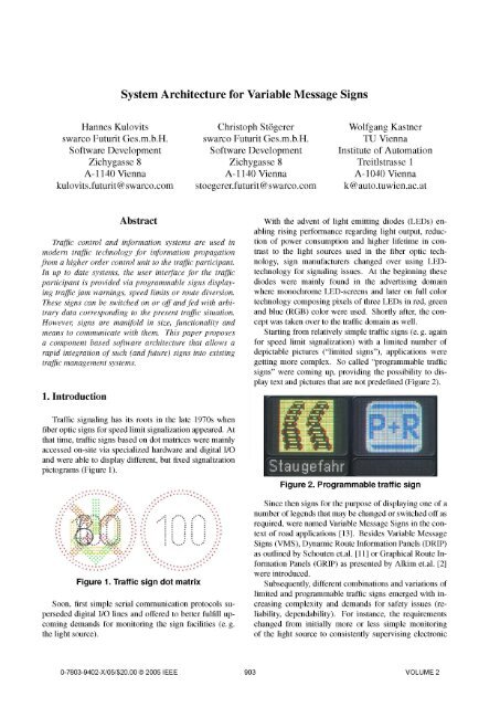
pictograms (Figure 1).<br />
.<br />
. . . . . . 6 .<br />
Figure 1. Traffic sign dot matrix<br />
Soon, first simple serial communication protocols superseded<br />
digital I/O lines and offered to better fulfill upcoming<br />
demands <strong>for</strong> monitoring the sign facilities (e. g.<br />
the light source).<br />
With the advent of light emitting diodes (LEDs) enabling<br />
rising per<strong>for</strong>mance regarding light output, reduction<br />
of power consumption and higher lifetime in contrast<br />
to the light sources used in the fiber optic technology,<br />
sign manufacturers changed over using LEDtechnology<br />
<strong>for</strong> signaling issues. At the beginning these<br />
diodes were mainly found in the advertising domain<br />
where monochrome LED-screens and later on full color<br />
technology composing pixels of three LEDs in red, green<br />
and blue (RGB) color were used. Shortly after, the concept<br />
was taken over to the traffic domain as well.<br />
Starting from relatively simple traffic signs (e. g. again<br />
<strong>for</strong> speed limit signalization) with a limited number of<br />
depictable pictures ("limited signs"), applications were<br />
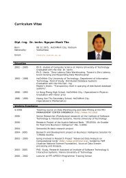
getting more complex. So called "programmable traffic<br />
signs" were coming up, providing the possibility to display<br />
text and pictures that are not predefined (Figure 2).<br />
Figure 2. Programmable traffic sign<br />
Since then signs <strong>for</strong> the purpose of displaying one of a<br />
number of legends that may be changed or switched off as<br />
required, were named <strong>Variable</strong> <strong>Message</strong> <strong>Signs</strong> in the context<br />
of road applications [13]. Besides <strong>Variable</strong> <strong>Message</strong><br />
<strong>Signs</strong> (VMS), Dynamic Route In<strong>for</strong>mation Panels (DRIP)<br />
as outlined by Schouten et.al. [11] or Graphical Route In<strong>for</strong>mation<br />
Panels (GRIP) as presented by Alkim et.al. [2]<br />
were introduced.<br />
Subsequently, different combinations and variations of<br />
limited and programmable traffic signs emerged with increasing<br />
complexity and demands <strong>for</strong> safety issues (reliability,<br />
dependability). For instance, the requirements<br />
changed from initially more or less simple monitoring<br />
of the light source to consistently supervising electronic<br />
0-7803-9402-X/05/$20.00 © 2005 IEEE<br />
903 VOLUME 2
* data processing<br />
* error detection<br />
* traffic situation reporting<br />
* autonomous control<br />
I<br />
Traffic Management and<br />
In<strong>for</strong>mation Center<br />
* data processing<br />
* data collection<br />
* video monitoring<br />
* global control<br />
Sub-Station<br />
B<br />
Sub-Station<br />
* data processing<br />
* error detection<br />
*<br />
traffic situation reporting<br />
Local Control Unit<br />
(Outstation)<br />
m* anual control<br />
* on-site control<br />
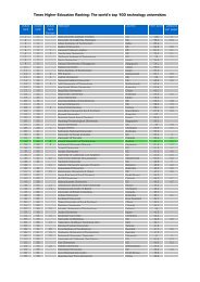
Figure 3. Structure of traffic management systems<br />
j<br />
components, inputs and outputs (e.g. data connection,<br />
power supply). Also detection units like humidity and luminosity<br />
sensors were integrated in such road traffic devices.<br />
The underlying communication had to be adapted and<br />
re-designed as well. Regarding physical media and protocol<br />
standards, fiber optic communication lines and the<br />
use of the Internet Protocol (IP) became an option in the<br />
traffic control domain and broadened the range of possibilities<br />
<strong>for</strong> the development of new applications especially<br />
<strong>for</strong> remote monitoring and control.<br />
Our work outlines problems of today's traffic management<br />
systems regarding communication standardization<br />
as well as customization of VMS and presents a configurable<br />
system architecture to overcome increasing demands<br />
regarding flexibility and enabling short development<br />
times <strong>for</strong> new features.<br />
The remainder of this paper is structured as follows:<br />
Section 2 presents the basic structure of a traffic management<br />
system and its components and discusses the main<br />
communication standards commonly used in traffic management<br />
systems. In Section 3 the goals <strong>for</strong> integrating<br />
VMS in a general framework are presented. While Section<br />
4 explains the component based software architecture,<br />
Section 5 shows the use of factory patterns to achieve<br />
protocol independence and to setup a generic transmission<br />
framework. Finally, Section 6 gives an outlook on future<br />
directions within the scope of this work.<br />
2. Traffic management systems<br />
Traffic management systems are composed of multiple<br />
control and monitoring entities coupled by different<br />
communication facilities and protocols (Figure 3). At the<br />
highest level a Traffic Management and In<strong>for</strong>mation Center<br />
(TMIC) collects data from Sub-Stations (SS) and provides<br />
it to its users <strong>for</strong> global strategies concerning road<br />
traffic monitoring and control. Sub-Stations are responsible<br />
<strong>for</strong> intermediate data collection. They are interconnected<br />
to one or more Local Control Units (LCUs) that are<br />
in turn wired to sensors (e. g. detector loops, radar detectors)<br />
and actuators (e. g. gates, traffic lights, VMS) and are<br />
responsible <strong>for</strong> data processing and autonomous control<br />
jobs. A LCU is composed of a Control Module and (optional)<br />
I/O-Converters. It is the task of an I/O-Converter<br />
to translate incoming requests from the LCU to a vendor<br />
specific protocol and respond to the LCU adhering to a<br />
standardized communication protocol (see below).<br />
The number of levels involved depends on size and<br />
complexity of the overall traffic management system. The<br />
minimum system configuration can be composed of some<br />
autonomously acting LCUs. Applications in this case may<br />
904<br />
VOLUME 2
care <strong>for</strong> the visualization of successive speed reduction<br />
<strong>for</strong> a specific section of road. This could be handled <strong>for</strong><br />
instance via three VMS with 500 m in between displaying<br />
130 km/h, 100 km/h and 80 km/h, respectively. The<br />
maximum system configuration consists of multiple levels<br />
of control and monitoring facilities, where each level<br />
is designed <strong>for</strong> autonomous operation as a kind of fallback<br />
in case of breakdown of a higher order level facility.<br />
Applications in this case include sophisticated traffic jam<br />
collision detection mechanisms and control of VMS with<br />
instructions <strong>for</strong> rerouting.<br />
Throughout the hierarchical structure, communication<br />
facilities differ in requirements depending on the levels involved.<br />
After several pilot projects were started, some regional<br />
restricted (de-facto) standards regarding communication<br />
protocols and facilities were introduced. The most<br />
important ones are listed in Table 1.<br />
Table 1. Communication standards in the<br />
traffic domain: overview<br />
Communication standard<br />
TLS [5]<br />
TLS over IP [4]<br />
DAP [14]<br />
NTCIP [1]<br />
Country of origin<br />
Germany<br />
Austria<br />
Netherlands<br />
US<br />
Up to now, these communication standards are dedicated<br />
to specific communication levels of a traffic management<br />
system structure. Thus, one single standard cannot<br />
be applied to a fully deployed traffic management system,<br />
i. e. from its highest level A to its lowest levels D<br />
or E (cf. Figure 3). Table 2 shows <strong>for</strong> each mentioned<br />
protocol its position and the devices included.<br />
Table 2. Communication standards in the<br />
traffic domain: levels and devices involved<br />
Communication<br />
Data exchange<br />
standard Levels between<br />
device device<br />
TLS over IP A TMIC SS<br />
TLS over IP B SS LCU<br />
TLS B SS LCU<br />
TLS C SS I/O-Conv.<br />
TMIC or<br />
DAP (A - C) SS or End device<br />
LCU<br />
TMIC or<br />
NTCIP (A - C) SS or End device<br />
TMIC<br />
3. Goals<br />
The remainder of this paper focuses on the communication<br />
between end devices, especially VMS, and - depending<br />
on the system structure - control entities on the<br />
next higher level. In the following, these control entities<br />
are summarized under the term Higher Order Control<br />
Units (HOCU). Typical instances of HOCUs can<br />
be LCUs, Sub-Stations, and TMICs. Moreover, VMS<br />
can be subdivided into sign units of different types (e. g.<br />
monochrome/bi-color/RGB signs, limited signs) where<br />
each sign unit is handled by a specific sign controller and<br />
its proprietary protocol. An exemplary VMS could consist<br />
of one limited sign part and three text lines (Figure 4).<br />
Figure 4. Composition of a VMS<br />
Thus, <strong>for</strong> a smooth integration of VMS in a general<br />
framework, flexibility has to be guaranteed. From a technical<br />
point of view, this integration requires on the one<br />
hand support <strong>for</strong> the numerous communication standards<br />
presented in the last section, and support <strong>for</strong> different sign<br />
units with their underlying proprietary access and functionality<br />
on the other hand.<br />
Data provided from the connected sensors of a VMS<br />
must be collected and <strong>for</strong>warded to the corresponding<br />
HOCU. In turn, a VMS receives new configuration<br />
and operational in<strong>for</strong>mation. The communication to the<br />
HOCU has to be supported regardless which protocol<br />
standard is used in the levels A, B or C. For the lowest<br />
levels D and E, it is essential to setup a unified access<br />
to the sign controllers.<br />
Depending on the data gathered, autonomous actions<br />
must be taken by the VMS itself. For example, when<br />
a connected sensor reports that luminosity decreases<br />
steadily, the brightness of the sign units must be adapted<br />
correspondingly.<br />
Since the overall traffic management system is a distributed<br />
one by nature, there are high demands on transparency<br />
and scalability. To achieve certain flexibility regarding<br />
the location of the whole system's logic, the different<br />
parts of the system architecture under discussion<br />
must be independent of the machine they are running on<br />
(location transparency). Thus, the design has to provide<br />
an architecture where parts may be running on a HOCU<br />
while other parts are swapped out to the end-device. Furthermore,<br />
the number of sign units as well as their arrangement<br />
and composition must not be fixed or predefined.<br />
There<strong>for</strong>e, it should be possible to care <strong>for</strong> a variable and<br />
configurable number of sign units (scalability).<br />
In any case, due to the fact, that a VMS may be composed<br />
of different sign units, each one must be explicitly<br />
manageable and addressable. For this reason, unicast and<br />
broadcast mechanisms to the sign units must be provided.<br />
905<br />
VOLUME 2
Specific protocol<br />
Communicator<br />
Request action via<br />
standardized ------------------------------------<br />
interface<br />
4<br />
Response to request<br />
via standardized<br />
poi nt)<br />
Controller<br />
FuturitCom protocol<br />
Request action vial<br />
standardized ------------------------------------<br />
interface<br />
------------------------------------4<br />
Response to request<br />
via standardized<br />
poi_nt)<br />
PLC Service<br />
Figure 5. Communication interface schema<br />
4. Software architecture<br />
From an economic point of view, the development<br />
costs (especially <strong>for</strong> future extensions) have to be kept as<br />
low as possible. In addition, the ability to react to new<br />
markets needs (e. g. integration of protocols <strong>for</strong> communication<br />
with HOCUs) has to be done as fast as possible.<br />
There<strong>for</strong>e our approach is to integrate the I/O-Converter's<br />
functionality as part of the LCU using component technology<br />
with the goal of shortening reaction times when<br />
adopting different protocols in a configurable and flexible<br />
way.<br />
The following higher order requirements had to be met:<br />
* The solution had to be designed in a highly flexible,<br />
adaptable and distributed way.<br />
* The coupling of the components had to be held as<br />
low as possible to ease software updates (integration<br />
of further protocols) and minimize error propagation.<br />
* The solution had to provide a high degree of stability<br />
and reliability. There<strong>for</strong>e it is necessary to execute<br />
the software in some kind of system mode and start<br />
running it automatically after computer restart without<br />
user actions being taken.<br />
* Most notably, the solution had to be based on a MS-<br />
Windows embedded operating system.<br />
To meet the main requirements the following technology<br />
decisions were taken:<br />
* The Rational Unified Process [9] was used as the<br />
software life cycle, due to the fact that this approach<br />
allows <strong>for</strong> an architecture-centric development process.<br />
* To provide a range of services <strong>for</strong> component interaction,<br />
from services promoting component integration<br />
on a single plat<strong>for</strong>m, to component interaction across<br />
heterogeneous networks, COMIDCOM [7] was chosen.<br />
* As the components must be able to (1) run in the<br />
background of the system, (2) start automatically in<br />
case of a system reboot, (3) execute without user login,<br />
the decision was taken to use MS-Windows Services.<br />
Finally, the software architecture was divided into three<br />
independent and self-contained components, namely PLC<br />
Service, Communicator and Controller discussed in more<br />
detail in the remainder of this section (Figure 5).<br />
4.1. PLC Service<br />
The PLC Service is responsible <strong>for</strong> interfacing with the<br />
underlying hardware (in our case this is a third party PLC<br />
system) and provides an (abstract) interface to it. Thus,<br />
components that use the PLC Service are completely hardware<br />
independent. Consequently, whenever the PLC system<br />
is to be replaced, the only part of the software architecture<br />
that has to be adapted is the PLC Service.<br />
906<br />
VOLUME 2
Moreover, the PLC Service cares <strong>for</strong> a publishersubscriber<br />
mechanism. It provides notifications <strong>for</strong> interested<br />
subscribers each time a modification of the process<br />
data occurs. Such interesting events can be <strong>for</strong> instance<br />
the change of luminosity or the change of temperature.<br />
Via the PLC Service it is possible to define <strong>for</strong> interesting<br />
parts of the process data (so-called I/O points) a name<br />
and description, a corresponding unit, a factor <strong>for</strong> scaling<br />
purpose, a range <strong>for</strong> the scaled value, as well as a time slot.<br />
In case of an updated value that is stable within the specified<br />
time slot, the component provides it to subscribers<br />
via a dedicated connection point. Each I/O point is configurable<br />
regarding its address, where its current values<br />
can be derived from. In addition, the PLC Service allows<br />
configuration issues supporting to categorize and store the<br />
connected I/O points in groups called I/O-Categories.<br />
The benefit of the PLC Service lies in this configurability<br />
which enables a customization of the whole system<br />
without changing the PLC Service application itself. The<br />
setup process consists of two important phases. The first<br />
one copes with the creation of the appropriate PLC program<br />
in the underlying PLC application the PLC Service<br />
is connected to. The second one tackles the connection to<br />
the underlying PLC application (i. e. communication facilities)<br />
and logging issues by configuring the system using<br />
an XML configuration file.<br />
4.2. Controller<br />
The Controller component has to manage the communication<br />
to a configurable quantity of different sign controllers<br />
belonging to one or more physical VMS. Thus,<br />
the most important task of the Controller is to provide a<br />
uni<strong>for</strong>m interface <strong>for</strong> communicating with them. This interface<br />
is bundled into the so-called FuturitCom protocol<br />
(Figure 6).<br />
1.%<br />
Sign<br />
Sign<br />
controller 1 controller 2<br />
Hardware<br />
specific<br />
protocol 1<br />
Hardware<br />
specific<br />
protocol 2<br />
Sign<br />
*.. controller n<br />
Figure 6. FuturitCom protocol<br />
Hardware<br />
specific<br />
protocol n<br />
K<br />
The communication to sign controllers can be handled<br />
either via a serial connection or via UDP/IP. To make each<br />
sign controller as well as the whole VMS addressable,<br />
the sign units and their corresponding Controller need a<br />
unique address. For this reason, the address structure x.y<br />
was introduced where x stands <strong>for</strong> the address of the Controller<br />
and y <strong>for</strong> the address of a sign unit. To operate all<br />
sign units at once in the custody of a specific Controller<br />
the sub-address is set to zero.<br />
The component offers the full command language set<br />
of the FuturitCom protocol via the IFuturitCom interface.<br />
The interface includes functions like Po ll ()<br />
which is used to determine the status of the sign,<br />
SetBrightness (), <strong>for</strong> setting the current luminosity<br />
of the sign, or SetContent () to upload a specific<br />
content (e. g. a bitmap). Following the address scheme,<br />
each method needs the address of the Controller and the<br />
sub-address of the sign unit to uniquely identify the corresponding<br />
part of the sign. As a result the Controller<br />
component enables an absolute transparent, uni<strong>for</strong>m and<br />
coherent way of controlling and monitoring the sign connected<br />
to the system.<br />
Furthermore, the component cares <strong>for</strong> an event interface,<br />
called IFuturitComEvents, which must be implemented<br />
by each user of the Controller component.<br />
This interface contains a counterpart <strong>for</strong> each method contained<br />
in the IFuturitCom interface. A method of the<br />
IFuturitComEvents interface is activated whenever<br />
a response of a call to the corresponding IFuturitCom<br />
method is ready. For instance, to determine the status of<br />
a sign, the Po ll () command must be used. After the<br />
Controller processed the command, it notifies the caller<br />
by invoking the corresponding OnPol () method of the<br />
IFuturitComEvents interface.<br />
Last but not least, the Controller is responsible <strong>for</strong> autonomous<br />
control. There<strong>for</strong>e, it reacts to data received<br />
from the PLC Service, such as controlling the brightness<br />
of a VMS autonomously. For this reason, it can subscribe<br />
to the events provided by the PLC Service.<br />
The configuration of the Controller is divided up into<br />
two parts: The first part deals with the communication,<br />
i. e. what kind of communication (serial or UDP/IP) shall<br />
be used, and which sign units are driven by the Controller.<br />
The second part covers issues <strong>for</strong> autonomous<br />
control (e. g. automatically dimming the sign) and safety<br />
relevant features (e. g. cyclic testing of LED-displays).<br />
4.3. Communicator<br />
Figure 3 outlined that a VMS is integrated into a traffic<br />
management system where different units are involved.<br />
As mentioned at the beginning of this section, one important<br />
requirement is to cut down on the need to use an I/O-<br />
Converter to enable the communication with the VMS.<br />
However, without an I/O-Converter the VMS has to handle<br />
the different communication standards on its own (cf.<br />
Table 2). Thus, the HOCU directly connects to the VMS<br />
in order to control it via varying commands.<br />
The interface to the HOCU is provided by the Communicator<br />
component. The main challenge of the Communi-<br />
907<br />
VOLUME 2
cator is to per<strong>for</strong>m the following tasks independently of<br />
the protocol used (e. g. FuturitCom, TLS, SiTOS [12]):<br />
* wait <strong>for</strong> an incoming request from a HOCU.<br />
* validate the request, i. e. send a positive acknowledgment,<br />
if it is correct, return a negative acknowledgment,<br />
if the request is invalid, or ignore the request<br />
in all other cases.<br />
* delegate the request to the Controller component<br />
which communicates with the underlying VMS and<br />
its sign units.<br />
* wait <strong>for</strong> a response from the Controller component.<br />
* return the response to the HOCU.<br />
5. Communication based on factory patterns<br />
The whole system must be configurable in a way<br />
that allows to choose between different command language<br />
sets be<strong>for</strong>e run-time. This requirement especially<br />
bothers the Communicator, <strong>for</strong> it has to react to commands<br />
requested by the HOCU. To solve this problem<br />
two abstract classes were defined. The first one, named<br />
GenericTelegram, <strong>for</strong>ms the base class <strong>for</strong> the different<br />
telegrams of the supported command language<br />
sets. It provides an interface <strong>for</strong> retrieving the telegram<br />
byte stream and its length. The second class, called<br />
Transmission, offers an interface <strong>for</strong> establishing and<br />
closing a connection, and transmitting telegrams. It acts<br />
as base class <strong>for</strong> the different supported <strong>for</strong>ms of communication<br />
mechanisms (serial and UDP/IP).<br />
IFuturitComTelegramI<br />
transmission framework as an integral part of their functionality.<br />
The Controller utilizes the framework to communicate<br />
with its connected sign controllers and the Communicator<br />
needs it to interact with the HOCU.<br />
The main functionality of the transmission framework<br />
(send and receive commands) seems not to be a thrilling<br />
job and suggests that there should be ready-to-use solutions<br />
(i. e. libraries) available. However, in our case<br />
two requirements make it a very special task and, as far<br />
as we know, unique: transmitting of commands must<br />
be per<strong>for</strong>med in a very generic way in terms of (1) the<br />
used command language set and (2) the desired communication<br />
mechanisms. To solve this problem we propose<br />
a design where the transmission framework rests upon<br />
the abstract classes GenericTelegram (Figure 7) and<br />
Transmis s ion (Figure 8), only. In addition, <strong>for</strong> both<br />
classes the Abstract Factory Pattern [6] is chosen. This<br />
decision enables a very flexible design that can be easily<br />
adapted in two directions: the first one is related to the desired<br />
way of communication and the second one opens facilities<br />
to rapidly react to upcoming command languages.<br />
Forthcoming extensions have never to touch the transmission<br />
framework regardless whether an additional way of<br />
communication (e. g. TCP/IP) or a further command language<br />
set (e. g. NTCIP) has to be implemented.<br />
UDPTransmission<br />
+Send(<br />
#EstablishConnection(<br />
#CloseConnectiono<br />
SerialTransmission<br />
+Send(<br />
#EstablishConnection(<br />
#CloseConnection(O<br />
Transmission<br />
#EstablishConnectiono(<br />
#CloseConnectiono . i GenericTelegram<br />
+Initialize()<br />
+UnInitializeO<br />
+Sendo<br />
|TransmissionFactory<br />
|+CreateTransmission()o<br />
UDPTransmissionFactory<br />
+CreateTransmission(<br />
SerialTransmissionFactory<br />
+CreateTransmission(<br />
Figure 8. Transmission factory<br />
FuturitComTelegramFactory TLSTelegramFactory<br />
+CreateTelegram(<br />
+CreateTelegramo<br />
Figure 7. Telegram factory<br />
These two classes build the essential components of<br />
a transmission framework used to send and receive telegrams.<br />
Both, the Controller and Communicator use the<br />
By means of the method CreateTelegram(), a<br />
telegram of the configured protocol (e. g. TLS) can be created<br />
from a given byte stream, which will be provided via<br />
a parameter. The method throws an exception in case the<br />
telegram is not valid, i. e. if it does not correspond to the<br />
command language set (e. g. FuturitCom) or is syntactically<br />
incorrect. If the telegram is valid, it returns an object<br />
of the created telegram represented by its superclass<br />
GenericTelegram.<br />
908<br />
VOLUME 2
Figure 9 shows, in a simplified way, how a command<br />
is processed by the system including the Communicator<br />
and Controller component. The Communicator uses the<br />
previously explained transmission factory to provide an<br />
interface (serial or UDP/IP) to the HOCU. This framework<br />
establishes the connection to the HOCU and thus<br />
provides the Communicator with the commands sent by<br />
the HOCU. Vice versa, it provides dedicated methods <strong>for</strong><br />
sending commands to the HOCU.<br />
A byte stream received by the Communicator is<br />
checked, whether it is valid (syntactically correct) and<br />
belongs to a supported command language. This is<br />
done by passing the byte stream to the protocol specific<br />
implementation (predefined by the configuration)<br />
of CreateTelegram () which creates the coffesponding<br />
telegram and returns a reference to its base class<br />
(GenericTelegram). Next, a mapping to the corresponding<br />
COM method is accomplished. There<strong>for</strong>e<br />
the kind of telegram (e. g. SetBrightness) and the parameters<br />
(e. g. brightness level) must be accessible to<br />
assemble the COM call. Afterward, the corresponding<br />
Controller method can be invoked. The corresponding<br />
response is delivered via the implementation of the<br />
IFuturitComEvents interface.<br />
The Controller's challenge is to carry out the command<br />
(e. g. adjusting the brightness of the sign) and to respond<br />
to the COM call via the event sink to notify the caller of<br />
the result of the processing. Depending on the configuration,<br />
the Communicator blocks until the response from<br />
the Controller arrives or a certain timeout expires. When<br />
the Controller replies within the timeout, the received response<br />
event is translated into the corresponding answer<br />
telegram of the configured command language.<br />
Communicator<br />
Command >| ITelecramFactory<br />
Response<br />
<<br />
CreateTele ram n<br />
GenericTelegram<br />
Create<br />
CreateTelegram<br />
ITelegram<br />
Response<br />
ResnonseTelecramFactorv<br />
Controller<br />
Figure 9. Communication sequence<br />
6. Conclusion and outlook<br />
ProcessCommand<br />
The software architecture presented followed an extensive<br />
requirements analysis with the primary goal of<br />
eliciting today's communication mechanisms in the traffic<br />
management domain. For describing the architecture,<br />
the Rational Unified Process and a five-view approach [8]<br />
which covers a logical view, implementation view, process<br />
view, deployment view and Use-Case view was applied.<br />
E. Gamma's design patterns and the second volume<br />
of the POSA series [10] can be seen as the most important<br />
references <strong>for</strong> the system architecture and design.<br />
Regarding the implementation, some limitations exist<br />
that pave the way <strong>for</strong> our future work. As already explained,<br />
the task of the Communicator is to accept commands<br />
(which, in general, are telegrams) of any standardized<br />
protocol, hand them over to the Controller <strong>for</strong> further<br />
processing and <strong>for</strong>warding the response to the caller.<br />
Actually, this task could be embedded into an arbitrary<br />
I/O-Converter. However, in the current version of the implementation,<br />
such an I/O-Converter must be based on an<br />
architecture supporting a MS-Windows operating system.<br />
To become plat<strong>for</strong>m independent, the next step is to implement<br />
the Communicator based on the Apache Portable<br />
Runtime (APR) [3] and thus avoid future vendor specific<br />
lock-ins.<br />
References<br />
[1] AASHTO, ITE, and NEMA. NTCIP: National transportation<br />
communications <strong>for</strong> ITS protocol. http: //www.<br />
ntcip. org, 2005.<br />
[2] T. Alkim, P. van der Mede, and W. Janssen.<br />
route in<strong>for</strong>mation on <strong>Variable</strong> <strong>Message</strong> <strong>Signs</strong>.<br />
Graphical<br />
In loth IEE<br />
International Conference on Road Transport In<strong>for</strong>mation<br />
and Control, pages 32- 36, 2000.<br />
[3] Apache Software Foundation. Apache Portable Runtime<br />
(APR). http: / /apr. apache. org, 2005.<br />
[4]<br />
[5]<br />
ASFINAG. TLS over IP (technical specification), 2004.<br />
BASt. Technische Lieferbedingungen fur Streckenstationen<br />
(TLS), 2002.<br />
[6] E. Gamma, R. Helm, R. Johnson, and J. Vlissides. Design<br />
Patterns: Elements ofReusable Object-Oriented Software.<br />
Addison Wesley, 1995.<br />
[7] M. Horstmann and M. Kirtland. DCOM architecture.<br />
http://msdn.microsoft.com/library/<br />
default.asp?url=/library/en-us/dndcom%<br />
/html/msdn_dcomarch. asp, 1997.<br />
[8] P. Kruchten. Design patterns: Elements of reusable objectoriented<br />
software. IEEE Software, 12(6):42 - 50, 1995.<br />
[9] P. Kruchten. The Rational Unified Process. An Introduction<br />
(3rd Edition). Addison Wesley, 2003.<br />
[10] D. Schmidt, M. Stal, H. Rohnert, and F. Buschmann.<br />
Pattern-Oriented Software <strong>Architecture</strong>, Vol. 2: Patterns<br />
[11]<br />
<strong>for</strong> Concurrent and Networked Objects. Wiley, 2000.<br />
W. Schouten, M. van Lieshout, and W. Spit. VMS in<br />
the polder. In gth IEE International Conference on Road<br />
Transport In<strong>for</strong>mation and Control, pages 222 - 226,<br />
1998.<br />
[12] Siemens AG. Interface <strong>for</strong> graphical displays (SiTOS),<br />
2004.<br />
[13] R. W. Stain<strong>for</strong>th. The application of <strong>Variable</strong> <strong>Message</strong><br />
<strong>Signs</strong> <strong>for</strong> traffic management and safety. In IEE Colloquium<br />
on Motorway Widening: Opportunities <strong>for</strong> New<br />
Communications and Lighting, pages 12/1 - 12/3, 1991.<br />
[14] TZWED. Dynamisch Route In<strong>for</strong>matie Paneel Applicatielaag<br />
Protocol (DAP), 1999.<br />
909<br />
VOLUME 2
![Informationsvisualisierung [WS0708 | 01 ]](https://img.yumpu.com/22537403/1/190x143/informationsvisualisierung-ws0708-01-.jpg?quality=85)