OVERCOMING STRESSED SATELLITE NETWORKS USING ...
OVERCOMING STRESSED SATELLITE NETWORKS USING ...
OVERCOMING STRESSED SATELLITE NETWORKS USING ...

You also want an ePaper? Increase the reach of your titles
YUMPU automatically turns print PDFs into web optimized ePapers that Google loves.
<strong>OVERCOMING</strong> <strong>STRESSED</strong> <strong>SATELLITE</strong> <strong>NETWORKS</strong> <strong>USING</strong> ALTERNATIVE<br />
COMMUNICATIONS<br />
ABSTRACT<br />
As advanced communications techniques reach capacity,<br />
have reduced performance or system availability, or<br />
become unusable, the warfighter must have a reliable,<br />
high-capacity communications system in place and<br />
standing ready to supplant the degrading systems.<br />
Events in the recent past have shown satellites<br />
vulnerable to a number of ills or potential problems that<br />
could be debilitating.<br />
This paper addresses supporting the warfighter as<br />
satellite communications (SATCOM) vanishes during<br />
stressed communications conditions such as jamming.<br />
The text presents example networks encompassing<br />
representative operational conditions and scenarios.<br />
Various analysis results present available user rates,<br />
expected latencies, and network capacities replacing the<br />
stressed SATCOM links as well as future potential<br />
research directions.<br />
INTRODUCTION AND BACKGROUND<br />
Stressed communications systems disrupt data<br />
transmission and hinder information transfer. As a result<br />
of Net-Centric Warfare, today’s warfighter depends even<br />
more on critical communications to fight battles with<br />
decisive actions and do so on a 24/7 basis. Various<br />
disruptive methods such as electronic, physical or other<br />
invasive techniques can be used as an attacking method.<br />
While physical attacks have found their way into our<br />
news in recent times, this paper focuses on the use of<br />
electronic jamming and the resulting stress satellite<br />
communication systems and alternatives to overcome<br />
jamming.<br />
High-speed satellite communications typically emanate<br />
from reflector antennas that basically radiate and receive<br />
in very narrow beams. As such, a jamming signal would<br />
have to be in line with the view to the satellite from the<br />
terminal, or the jammer must radiate to the satellite.<br />
Downlink jamming would affect only one terminal while<br />
an uplink jamming would affect all terminals connected<br />
through the satellite. This more wide-spread uplink<br />
jamming comes in a variety of forms and each has its<br />
own unique features that must be countered. Table 1<br />
identifies some alternate communications techniques<br />
available to overcome jamming.<br />
Jerry Brand, Ph.D., P.E. Robert Bach<br />
Harris GCSD and Harris GCSD<br />
Melbourne, FL 32902 Melbourne, FL 32902<br />
jbrand01@harris.com rbach@harris.com<br />
1 of 6<br />
Table 1. Various techniques can be used to combat<br />
jamming<br />
Alternate Communications Techniques<br />
Signal Processing Jamming Mitigation Techniques<br />
Directional Antenna Beams<br />
Low Probability of Intercept/Detection Signals<br />
Alternate Network Path Routing<br />
High-Power Radio Frequency (RF) Burn-Through<br />
Free-Space Optics<br />
Adaptive Antenna Beams (Null-steering)<br />
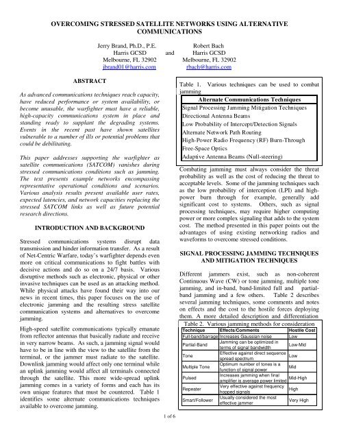
Combating jamming must always consider the threat<br />
probability as well as the cost of reducing the threat to<br />
acceptable levels. Some of the jamming techniques such<br />
as the low probability of interception (LPI) and highpower<br />
burn through for example, generally add<br />
significant cost to systems. Others, such as signal<br />
processing techniques, may require higher computing<br />
power or more complex signaling that adds to the system<br />
cost. The method presented in this paper points out the<br />
advantages of using existing networking radios and<br />
waveforms to overcome stressed conditions.<br />
SIGNAL PROCESSING JAMMING TECHNIQUES<br />
AND MITIGATION TECHNIQUES<br />
Different jammers exist, such as non-coherent<br />
Continuous Wave (CW) or tone jamming, multiple tone<br />
jamming, and in-band, band-limited full and partialband<br />
jamming and a few others. Table 2 describes<br />
several jamming techniques, some comments and notes<br />
on effects and the cost to the hostile forces deploying<br />
them. A more detailed description and differentiation<br />
Table 2. Various jamming methods for consideration<br />
Technique Effects/Comments Hostile Cost<br />
Full-band/barrage Increases Gaussian noise Low<br />
Partial-Band<br />
Jamming can be optimized in<br />
terms of signal bandwidth<br />
Low-Mid<br />
Tone<br />
Effective against direct sequence<br />
Low<br />
spread spectrum<br />
Multiple Tone<br />
Optimum number of tones is a<br />
function of signal power<br />
Mid<br />
Pulsed<br />
Increases jamming when final<br />
amplifier is average power limited Mid-High<br />
Repeater<br />
Very effective against frequency<br />
hopped signals<br />
High<br />
Smart/Follower<br />
Usually considered the most<br />
effective jammer<br />
Very High
can be found in [1]. Figure 1 illustrates the jamming<br />
environment from surface, airborne and space borne<br />
perspectives. These examples cover a broad spectrum of<br />
expected jamming techniques and supply a suitable<br />
baseline that waveforms can be tested against.<br />
Performance characteristics in terms of Bit Error Rate<br />
(BER), Symbol Error Rate (SER) and packet<br />
loss/throughput statistics can be calculated and used to<br />
optimize and further adapt the waveforms.<br />
Harris continues to build from a library of jamming<br />
models built and proven over the last several years.<br />
These proven jammer models facilitated the successful<br />
completion of a proprietary waveform with powerful<br />
Anti-Scintillation (AS) and Anti-Jam (AJ) capabilities.<br />
Such solid analysis structures supply a suitable starting<br />
point for the required analysis. Additionally, cognitive<br />
radios and smart routing capabilities provide other<br />
alternatives for jamming avoidance.<br />
Figure 1. Jammers prevent SATCOM from effectively<br />
transferring critical and timely warfighter information<br />
For effective jamming mitigation techniques, trades<br />
must be made in regard to waveform structure. Symbol<br />
interleaving and interleaving depth come forward as<br />
proven methods for overcoming various jamming<br />
conditions [2, 3]. Specific jamming signals and desired<br />
signals require specific interleaving for optimum stress<br />
protection. These analyses should include running<br />
simulations using sensitivity parameterizations and<br />
characterizations and specific traffic types such as voice,<br />
video and data.<br />
Gaussian noise jammers used against frequency hopped<br />
signals can be larger than the information bandwidth of<br />
the target, but narrower than the total hopped bandwidth<br />
[4]. Termed partial-band jammers, these can in some<br />
instances provide increased effectiveness by grouping<br />
symbol errors and thus defeating the error correction<br />
decoder. Interleaving of sufficient length, as designed<br />
2 of 6<br />
into Harris’ AS/AJ modem, defeats this strategy by<br />
"randomly" spacing out the symbol errors. The AS/AJ<br />
modem resides in the OM-88 Modem System [9].<br />
Figure 2 represents an example AJ Waveform’s<br />
performance against a barrage jammer in a fast-fading<br />
environment and the potential improvement that can be<br />
obtained using appropriate symbol coding and<br />
interleaving. Greater detail using similar methods may<br />
be found in Kosa’s [5] master thesis at the Naval<br />
Postgraduate School. While there are many types of<br />
jammers and many methods of classification, our paper<br />
focuses the discussion on the achievable network<br />
performance with an illustrative method of bypassing the<br />
satellite jamming environment altogether. Bypassing the<br />
jamming environment eliminates the need for more<br />
complex and expensive AJ equipment enabling the use<br />
of traditional and even commercial grade<br />
communications equipment.<br />
Bit Error Rate (BER)<br />
1.E+00<br />
1.E-01<br />
1.E-02<br />
1.E-03<br />
1.E-04<br />
1.E-05<br />
1.E-06<br />
1.E-07<br />
Anti-Jam<br />
1.E-08<br />
0 10 20 30<br />
Eb/No (dB)<br />
Jammed<br />
Figure 2. Significant performance improvements come<br />
from proper waveform formulation and manipulation<br />
Existing alternatives provide a most suitable means to<br />
overcome the effects of stressed communications easing<br />
the analysis requirements. Networking Radios capable<br />
of supplying a high-capacity and a high-availability<br />
readily provide a solution to bypass the jamming<br />
environment.<br />
<strong>NETWORKS</strong> & NETWORK RADIO BASED<br />
TECHNIQUES<br />
Harris’ High-Capacity Wireless Networking [6]<br />
solutions offer flexibility and high-rate networking for<br />
the warfighter. This includes the multi-channel software<br />
defined radio (SDR) based Highband Networking Radio<br />
(HNR) system. The HNR system takes advantage of<br />
robust Line-Of-Sight (LOS) waveforms operating above<br />
2 GHz. Similar SDRs built from proven designs provide
SATCOM as well enabling beyond LOS (BLOS)<br />
communication. Such high-capacity networks enable<br />
Open Systems Interconnection (OSI) Layer 2<br />
communication beyond 80 Mbps supplying capacity<br />
necessary to supply essential warfighter information for<br />
terrestrial, ground-to-air and air-to-air missions.<br />
The HNR radio system implements a wireless Wide<br />
Area Network (WAN) that connects LANs and their<br />
users together [7]. The HNR radio hosts the Highband<br />
Networking Waveform (HNW), an advanced waveform<br />
developed specifically for mobile, high capacity<br />
backbone networks [8]. The HNR radio and HNW stand<br />
as a top-candidate high-capacity network radio for<br />
backbone networks and as alternates for stressed<br />
SATCOM or airborne networks. Depending upon the<br />
location of the jammer, jamming can equally impact<br />
surface–to-surface and surface–to-air/space paths.<br />
However, in addition to the signal processing techniques<br />
discussed earlier, Network Radios offer other inherent<br />
features that mitigate jamming effects.<br />
Several features offered by today’s Networking Radios<br />
such as the HNR, offer mitigation to jammers. 1) The<br />
robust networks composed of terrestrial and air tier paths<br />
offer path diversity enabling the automatic routing of<br />
data around the jammer. 2) Directional-beam links<br />
versus omni-directional beam links provide improved<br />
performance as more power can be applied to the link<br />
signal to increase the signal power and hence reduce the<br />
Jamming-to-Signal (J/S) ratio. Additionally, at the<br />
receiving end, directional links are less susceptible to the<br />
jammer’s energy not directly in the link path. 3) To<br />
compensate for data loss during jamming, Network<br />
Radios such as the HNR can rely upon several different<br />
transport protocols such as Transmission Control<br />
Protocol (TCP), User Datagram Protocol (UDP) and the<br />
Real-time Transport Protocol (RTP). TCP will<br />
guarantee packet delivery, although this may effectively<br />
decrease link throughput due to packet retransmissions.<br />
UDP does not guarantee packet delivery but carries less<br />
overhead. Most Network Radios using these<br />
transmission protocols have the ability to buffer data for<br />
retransmission of lost data. RTP provides for multimedia<br />
streaming data and includes time-stamping such<br />
that out-of-order packets may be correctly reassembled<br />
and synchronized. 4) The ability of Network Radios to<br />
automatically adapt link data rates based upon link<br />
quality also helps in a jamming environment. If link<br />
quality degrades, the radio will throttle back to a lower<br />
data rate allowing the link to remain viable.<br />
Various traffic modes present different Information<br />
Exchange Rates (IER) and differing overhead loads.<br />
Voice, video and data offer the three main categories for<br />
consideration while other small packets stand as another<br />
category for investigation. Analog voice<br />
3 of 6<br />
communications using internet protocols require<br />
digitization called vocoding prior to transmission.<br />
Various vocoders find practical use such as Mixed<br />
Excitation Linear Prediction (MELP) or G.711. MELP<br />
has become the MIL-STD-3005 since 1997 and G.711<br />
has been an ITU-T standard using pulse coded<br />
modulation (PCM) since 1972.<br />
These vocoding schemes may require near 50% to above<br />
90% overhead for voice transmission. Data transmission<br />
can also require a wide range of overhead from 100% for<br />
an acknowledgement to essentially 0% for a maximum<br />
length internet packet protocol (IPv4 for example).<br />
Image or video packets can require overhead ranging<br />
from just above 0% for a Joint Picture Experts Group<br />
(JPEG) image heading up to around 10% for UDP<br />
streaming video using the Maximum Transmission Unit<br />
(MTU). Table 3 shows some example coding rates and<br />
the resulting overhead expenses as well as a couple of<br />
other small packet examples. Khan [8] provides some<br />
Voice-over-Internet Protocol (VoIP) examples that<br />
illustrate the related overhead parameters.<br />
Quality of Service (QoS) and Service Level Agreements<br />
(SLA) are becoming a part of Network Centric<br />
communications. Currently, various methods exist to<br />
determine call priorities and these offer many<br />
opportunities for exploration. With such a plethora of<br />
QoS and SLA alternatives and choices, this brief article<br />
holds these ideas for examination in future works.<br />
Table 3. Coding overhead loads illustrate the required<br />
packet overhead for encrypted transmission<br />
Packet<br />
Info<br />
(Bytes)<br />
Network and<br />
Link<br />
Encrypted<br />
Total (bytes) Overhead<br />
Voice on RTP<br />
MELP Frame 6.75 1152 95.3%<br />
20 ms G.711 160 304 47.4%<br />
Images/Video on RTP<br />
Max Ethernet MTU on UDP 1500 1632 8.1%<br />
JPEG Image 48750 48896 0.3%<br />
Data on TCP<br />
Delayed Acknowledgement 0 1152 100.0%<br />
Max IP Packet Payload 65536 65680 0.2%<br />
Other Small Packets<br />
Simple SNMP Response 44 112 60.7%<br />
Simple RTCP Report 76 208 63.5%<br />
NETWORK PERFORMANCE UNDER JAMMING<br />
Jamming signals must be detected and analyzed to<br />
ensure mitigation techniques can be employed. Separate<br />
signal analysis receivers and systems can provide a<br />
suitable means of jamming determination and<br />
classification. Some networking radios can detect<br />
jamming presence and can do so at a level suitable for
avoidance. Figure 3 illustrates a warfighter network<br />
scenario where the satellite and airborne layers have<br />
been jammed (denoted by the large “X” through the<br />
links) and detected. This jamming eliminates the usual<br />
routing techniques and requires mitigation techniques.<br />
A<br />
82 Mbps<br />
4<br />
82 Mbps<br />
1<br />
X<br />
X<br />
XX 55 Mbps<br />
55 Mbps<br />
5<br />
55 Mbps<br />
82 Mbps<br />
2<br />
7<br />
6<br />
22 Mbps<br />
3<br />
B<br />
Figure 3. An example network takes over the<br />
communications network as jammers prevent SATCOM<br />
from effectively transferring critical and timely<br />
warfighter information<br />
In this scenario, nodes labeled “A” and “B” in Figure 3<br />
are maintaining a real-time critical information stream of<br />
10.5 Mbps over the satellite. This critical information<br />
includes streaming video, data and voice<br />
communications enabling strategic and tactical battle<br />
formulations and decisive actions. The jamming actions<br />
result in the disruption of the information flow from “A”<br />
to “B” as indicated by the “X”. Examining the links<br />
numbered “1”, “2” and “3” in Figure 3; an alternate<br />
route can supply the needed bandwidth and maintain the<br />
critical information flow between the nodes.<br />
As we examine the three links “1, “2” and ”3”, several<br />
features come to bear on the link capacities. First, link<br />
capacity must be shared among all of the connected<br />
nodes, reducing the amount of bandwidth available on<br />
each link for bypassing the jammer. Second,<br />
atmospheric effects (weather, multi-path, Fresnel) can<br />
limit the link performance. Table 4 details the available<br />
(OSI layer 3) link capacity for the three links under<br />
study and using an 80% load factor to handle traffic<br />
surges. Link #3 clearly limits the jamming bypass but<br />
fully covers the 10.5 Mbps satellite link with 11 Mbps<br />
available on an average basis. As such, the bypassing<br />
4 of 6<br />
results in the successful transfer of information<br />
overcoming the satellite jamming. However, since the<br />
maritime battlespace remains dynamic, alternative links<br />
“1”, “2” and “3” may need to be employed. As seen in<br />
Figure 3, the paths “4”, “5”, “6” and “7” can be<br />
employed to connect “A” with “B” but the available data<br />
rate capacity of each link must be closely studied.<br />
Table 4. OSI Layer 3 available rates for evenly<br />
distributed IERs show reasonable capacities<br />
Link<br />
Available<br />
(Mbps)<br />
Per Node<br />
Useable<br />
(Mbps)<br />
Per Link<br />
Useable<br />
(Mbps)<br />
1 82.0 65.6 21.9<br />
2 82.0 65.6 32.8<br />
3 55.0 44.0 11.0<br />
Figure 4 shows the available maximum capacity<br />
resulting from the number of nodes loading the channel<br />
with the dashed line indicating the example’s required<br />
10.5 Mbps. This channel sharing must always be<br />
considered to ensure adequate capacity remains available<br />
during stressed conditions such as jamming. Even with<br />
a fairly significant capacity, the number of supported<br />
nodes gets quickly limited. For example, a reasonably<br />
dense network of five or more connected nodes requires<br />
above 55 Mbps capacity per link to maintain the<br />
required average throughput of greater than 10.5 Mbps<br />
per link assuming a 100% network loading.<br />
Available Data Rate (Mbps)<br />
35.0<br />
30.0<br />
25.0<br />
20.0<br />
15.0<br />
10.0<br />
5.0<br />
82 Mbps<br />
55 Mbps<br />
22 Mbps<br />
100% Network Loading<br />
0.0<br />
2 3 4 5 6 7 8 9 10<br />
Nodes Loading per Channel<br />
Figure 4. Various channels present different<br />
availabilities limiting the number of connected nodes<br />
Going back to the problem at hand and as can be seen<br />
from Figure 3, the “6” path provides a 22 Mbps path.<br />
This 22 Mbps strictly limits the alternate path as the<br />
minimum available capacity. If the situation changes<br />
such that additional nodes require the use of “6” link<br />
because of routing or other stressful conditions, “7” must<br />
be considered as another viable route. Path “7” enables<br />
additional capacity as the minimal path stands at 55<br />
Mbps. Link “7” may also be used to share the load with<br />
“6” adding another dimension to the solution.
One other key item comes to light during this<br />
representative bypassing operation. Each node adds a<br />
delay because of networking and routing considerations.<br />
Generally speaking, transmission delays of up to 50 ms<br />
can be encountered at each node. This delay comes from<br />
waiting to transmit (multiplexing framing time) in a<br />
Time Division Multiple Access (TDMA) system for<br />
example, or from queuing times.<br />
For example using queue delay, if we have six nodes<br />
sharing a 22 Mbps link, assuming an average wait of<br />
three queue times at each node with four hops and a<br />
fixed frame size of 1000B results in a wait time of 4.4<br />
ms (3*4*1000*8/22.0E+06). The delay using a TDMA<br />
system with 25 ms framing delay would result in a 100<br />
ms delay (4*25). As such, considerable delays for the<br />
bypassed link can head into the hundreds of milliseconds<br />
as the number of nodes or hops increases.<br />
However, given this alternate link has replaced the<br />
stressed satellite link, these delays may even be less than<br />
those occurring from the satellite link delay. That is, the<br />
round-trip geosynchronous delay of about 250 ms<br />
reasonably compares to the bypassed network’s delay.<br />
Often times the satellite links require multiple hops that<br />
further increases the delay time.<br />
The ITU-T recommendation G.114 suggests 100 ms or<br />
less for an objective delay with 150 ms as acceptable<br />
delay for voice connections and 225 ms as satisfactory<br />
for transmission delay while a delay of 400 ms should<br />
not be exceeded [10]. These indicate that these alternate<br />
network route delays are in line with current commercial<br />
telephony customer expectations. Overall, the network<br />
delay resulting from using the bypassed links should<br />
meet the military customer’s expected delay as<br />
compared to a standard voice connected satellite link. In<br />
addition to transmission and routing delays, the network<br />
protocols also affect the alternate network routing<br />
efficiencies and will be examined later in this paper.<br />
An air tier provides an excellent alternative route to<br />
overcome delay as the network bypasses the satellite<br />
jamming. Figure 5 displays the air tier connectivity and<br />
data rates at specific ranges that clearly meet the IERs<br />
required by an alternate route. The air tier supplies a<br />
delay advantage by using single-hop connectivity as well<br />
as increased range. This range improvement results<br />
from the airborne advantage of increased LOS distance.<br />
The delay reduces to that of a single-hop or around 25<br />
ms from our TDMA example for each node connected<br />
from the aircraft; a significant improvement.<br />
Another feature that increases network capacity results<br />
from frequency reuse. Planned multi-channel radio<br />
network systems such as the next generation HNRv2<br />
(HNRv3) will provide multiple frequencies and hence<br />
increased capacity. The capacity increases about<br />
5 of 6<br />
proportionally to the number of independent channels<br />
supported.<br />
Figure 5. The air tier provides increased range at<br />
respectable data rates adding network capacity<br />
These channels require coordination and the scheduler<br />
must accommodate this complexity. For instance, the<br />
HNRv3 plans to use dual-channels and have about twice<br />
the network capacity. The network scheduler must<br />
coordinate the directions as well as the channel<br />
assignments and keep up with this added computational<br />
burden. The TDMA timing structure can accommodate<br />
this frequency reuse and truly offers a two-fold capacity<br />
increase.<br />
One last area for assessment resides with the routing and<br />
network management of the net-centric system. The<br />
many facets of this complex problem present issues far<br />
beyond this paper’s intent. Various papers have<br />
researched these topics and one paper [11] welldescribes<br />
the comparisons of multi-hop wireless ad hoc<br />
networks routing and protocols generally applicable to<br />
the alternatives described herein. Various wireless ad<br />
hoc network protocols present varying degrees of<br />
performance and several routing protocol routing design<br />
choices stand out.<br />
Destination-Sequenced Distance Vector (DSDV),<br />
Temporally-Ordered Routing Algorithm (TORA),<br />
Dynamic Source Routing (DSR), Ad hoc On-demand<br />
Distance Vector (AODV), Optimized Link State Routing<br />
(OLSR), Open Shortest Path First version 2 (OSPFv2)<br />
and Zone Routing Protocol (ZRP) have been studied and<br />
simulated in realistic environments and the results<br />
provided [11, 12]. Various parameters such as the<br />
number of nodes simulated, the number of hidden nodes,<br />
protocol extensions and adaptations, etc. can affect the<br />
simulations and must be considered as fundamental to<br />
the problem. Network scaling and physical conditions<br />
can also affect the networks efficiency as can parameter<br />
tuning and the distance between nodes. All in all, the<br />
choice of the particular routing protocol must be tailored
to application specific requirements. The HNW<br />
currently uses either OLSR or OSPFv3 with directional<br />
routing to meet net-centric requirements in a mobile ad<br />
hoc environment.<br />
For example, the popular OLSR has been compared to<br />
AODV and Ad hoc On-demand Multipath Distance<br />
Vector (AOMDV) in maritime environments<br />
demonstrating the varied nature of net-centric systems<br />
[13]. The various payload lengths couple with the<br />
protocol overhead and affect the initial packet delay as<br />
well as packet delivery ratio. For the sea states and<br />
number of nodes presented in [13] AODMV provided<br />
better efficiencies than did OLSR. AODMV also<br />
provides multiple paths during the discovery process and<br />
would fit well with the alternate routing principles<br />
previously described in this paper.<br />
CONCLUSIONS AND FUTURE DIRECTIONS<br />
This paper has shown that while recent events in satellite<br />
jamming and disruption raise concerns, methods and<br />
equipment exist today to work around or through the<br />
stressed conditions. AJ signal processing techniques can<br />
be used in satellite terminals and Network Radios to<br />
mitigate jamming threats while preserving network<br />
connectivity and availability.<br />
Further, Network Radios and IP based Networks have<br />
inherent capabilities to mitigate jamming threats. Future<br />
efforts should be considered for further waveform<br />
enhancements including greater protection levels,<br />
dynamic routing and cognitive radio processing.<br />
Various protocols and protocol adaptations must be<br />
considered and their applications appropriately applied<br />
to the alternate network paths for maximum efficiency.<br />
Finally, the airborne and surface tiers should examine<br />
alternate modulation and coding formats enabling yet<br />
higher data rates and additional alternate paths. These<br />
studies should consider working across the physical and<br />
higher OSI layers to determine the best overall network<br />
performance. These areas of study should further these<br />
multiple layer considerations as begun by Bernhardt, et.<br />
al. [14]<br />
REFERENCES<br />
[1] R. L. Peterson, R. E. Ziemer and D. E. Borth,<br />
Introduction to Spread Spectrum Communications,<br />
Englewood Cliffs, NJ: Prentice Hall, 1995, pp. 321-326.<br />
[2] A. J. Viterbi and I. M. Jacobs, "Advances in coding<br />
and modulation for noncoherent channels affected by<br />
fading, partial-band and multiple-access interference," in<br />
Advances in Communication Systems, Vol. 4. New<br />
York: Academic, 1975.<br />
6 of 6<br />
[3] P. J. Crepeau, “A connection between Rayleigh<br />
fading and worst-case partial band interference,”<br />
MILCOM Proc. 1989, vol. 3, pp. 693-696.<br />
[4] Jhong S. Lee, and Leonard E. Miller, “Error<br />
Performance Analyses of Differential Phase Shift-<br />
Keyed/Frequency-Hopping Spread-Spectrum<br />
Communication System in the Partial-Band Jamming<br />
Environments,” IEEE Trans. on Comm., May 1982, pp.<br />
943-952.<br />
[5] Irfan Kosa, “Performance of IEEE 802.11a Wireless<br />
LAN Standard over Frequency-Selective, Slowly Fading<br />
Nakagami Channels in a Pulsed Jamming Environment,”<br />
Thesis, Naval Postgraduate School, Monterey, CA, Dec<br />
2002, Ch. 4 and 5.<br />
[6] Harris GCSD Networking Brochure, High-Capacity<br />
Wireless Networking, 2007.<br />
http://download.harris.com/app/public_download.asp?fi<br />
d=1759<br />
[7] Harris Highband Networking Radio Overview,<br />
“HNR - High Band Networking Radio Overview”, 2007.<br />
http://download.harris.com/app/public_download.asp?fi<br />
d=1321<br />
[8] Farooq Khan, “VoIP Models for 802.20 System<br />
Performance Evaluation,” IEEE 802.20 Interim Meeting<br />
Vancouver, BC, Canada, January 12-16, 2004.<br />
http://www.ieee802.org/20/Contribs/C802.20-04-<br />
12.ppt#271,2,VoIP Models for 802.20 System<br />
Performance Evaluation<br />
[9] Harris GCSD Satellite terminal Brochure, OM-<br />
88(V)1/G AS Modem System, 2008.<br />
http://download.harris.com/app/public_download.asp?fi<br />
d=1964<br />
[10] ITU-T Recommendation G.114, Series g:<br />
Transmission Systems and Media, Digital Systems and<br />
Networks, One-way Transmission Time, May 2003.<br />
[11] J. Broch, D.A. Maltz, D> B. Johnson, Y-C Hu and<br />
Jorjeta Jetcheva, “A Performance Comparison of Multi-<br />
Hop Wireless Ad Hoc Network Routing Protocols”,<br />
MONICOM 98, Dallas, TX, pp. 85-97.<br />
[12] J. Hsu, S. Bhatia, M. Takai, R. Bagrodia and M.<br />
Acriche, “Performance of Mobile Ad Hoc Networking<br />
Routing Protocols in Realistic Scenarios”, MILCOM<br />
2003, IEEE, vol. 2, pp. 1268 – 1273.<br />
[13] P-Y Kong, H. Wang, Yu Ge, C-W Ang, S. Wen,<br />
J.S. Pathmasuntharam, M-T Zhou, H. V. Dien, “A<br />
Performance Comparison of Routing Protocols for<br />
Maritime Wireless Mesh Networks”, WCNC 2008,<br />
IEEE, pp. 2170–2175.<br />
[14] R. Bernhardt, J. B. Cain and W. Windham, “QOS<br />
Architecture for a Mobile Ad Hoc Network”, MILCOM<br />
2007.