IEEE Paper Template in A4 (V1) - ijmer
IEEE Paper Template in A4 (V1) - ijmer
IEEE Paper Template in A4 (V1) - ijmer

You also want an ePaper? Increase the reach of your titles
YUMPU automatically turns print PDFs into web optimized ePapers that Google loves.
International Journal of Modern Eng<strong>in</strong>eer<strong>in</strong>g Research (IJMER)<br />
www.<strong>ijmer</strong>.com Vol.2, Issue.1, pp-01-03 ISSN: 2249-6645<br />
TABLE I<br />
TRANSISTOR SIZE<br />
Device W/L(μm)<br />
M1,M2,M3 40/0.6<br />
M4,M5 20/0.6<br />
M6,M7,M8,M9 42/0.6<br />
M8,M9 50/0.6<br />
M10,M11 60/0.6<br />
M12,M13 0.8/0.6<br />
3. SIMULATION RESULTS<br />
The design of this Operational Transconductance Amplifier<br />
(OTA) is done us<strong>in</strong>g Cadence Tool. The Simulation results are<br />
done us<strong>in</strong>g Cadence Spectre environment us<strong>in</strong>g UMC 0.18 μm<br />
CMOS technology. The simulation result of the OTA shows<br />
that the open loop ga<strong>in</strong> of approximately 71 dB. The OTA has<br />
GBW of about 37 KHz.<br />
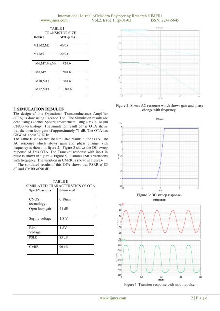
The Table II shows that the simulated results of the OTA. The<br />
AC response which shows ga<strong>in</strong> and phase change with<br />
frequency is shown <strong>in</strong> figure 2. Figure 3 shows the DC sweep<br />
response of This OTA. The Transient response with <strong>in</strong>put <strong>in</strong><br />
pulse is shown <strong>in</strong> figure 4. Figure 5 illustrates PSRR variations<br />
with frequency. The variation <strong>in</strong> CMRR is shown <strong>in</strong> figure 6.<br />
The simulated results of this OTA shows that PSRR of 85<br />
dB and CMRR of 90 dB.<br />
Figure 2: Shows AC response which shows ga<strong>in</strong> and phase<br />
change with frequency.<br />
TABLE II<br />
SIMULATED CHARACTERSTICS OF OTA<br />
Specifications Simulated<br />
CMOS<br />
technology<br />
Open loop ga<strong>in</strong><br />
0.18μm<br />
71 dB<br />
Figure 3: DC sweep response.<br />
Supply voltage<br />
Bias<br />
Voltage<br />
PSRR<br />
CMRR<br />
1.8 V<br />
1.8V<br />
85 dB<br />
90 dB<br />
Figure 4: Transient response with <strong>in</strong>put is pulse.<br />
www.<strong>ijmer</strong>.com<br />
2 | P a g e