Image Steganography and Global Terrorism - International Journal ...
Image Steganography and Global Terrorism - International Journal ...
Image Steganography and Global Terrorism - International Journal ...

You also want an ePaper? Increase the reach of your titles
YUMPU automatically turns print PDFs into web optimized ePapers that Google loves.
<strong>International</strong> <strong>Journal</strong> of Scientific & Engineering Research Volume 3, Issue 7, July-2012 1<br />
ISSN 2229-5518<br />
<strong>Image</strong> <strong>Steganography</strong> <strong>and</strong> <strong>Global</strong> <strong>Terrorism</strong><br />
Kaustubh Choudhary<br />
Abstract— This paper informs the reader how an innocent looking digital image hides a deadly terrorist plan. It analyses the strengths of image steganography<br />
<strong>and</strong> the reasons why terrorists are relying on it. It also aims to generate interest among the scientific community about <strong>Image</strong> steganography<br />
so that experts from multiple disciplines may join h<strong>and</strong>s for devising better steganalysis techniques against the global terrorism. In this paper a basic<br />
digital image is analyzed <strong>and</strong> based on this analysis an LSB based steganographic algorithm is designed. Using this algorithm a software is developed<br />
<strong>and</strong> its performance is compared with various other steganographic tools available on the internet. The result of this comparison explains us why steganography<br />
is so much preferred by terrorists. Various images <strong>and</strong> image related tables used in this paper are generated using MATLAB© Simulation Environment.<br />
Index Terms— CIA Compliance, Cyber Crime, <strong>Image</strong> <strong>Steganography</strong>, Information Security, LSB Insertion, <strong>Terrorism</strong>.<br />
—————————— ——————————<br />
I<br />
1 INTRODUCTION<br />
nformation Security rests on the three pillars of Confidentiality,<br />
Integrity <strong>and</strong> Availability of the communication channel.<br />
The trio is jointly called CIA compliance of the information<br />
network. The confidentiality means concealment of the<br />
sensitive information or software from the person who is not<br />
supposed to know the same. Integrity means trustworthiness<br />
of the data. It can be insured only if the data is obtained from<br />
the dependable sources <strong>and</strong> is frequently updated time to<br />
time. Availability means ability to use the information or resource<br />
as <strong>and</strong> when desired by the concerned user. To achieve<br />
this, most comm<strong>and</strong> <strong>and</strong> base level military communication<br />
use hack proof dedicated Wide Area Networks based on special<br />
Mil-Grade software protocol stack <strong>and</strong> a separate hardware<br />
at the physical layer itself. But even terrorist organizations<br />
need CIA Compliant communication channel. But most<br />
of their agents operate deep inside the civilian population <strong>and</strong><br />
cannot afford dedicated networks used by their government<br />
counterparts. In such a scenario only other communication<br />
channel available to them is the World Wide Web. In order to<br />
use Internet as a CIA Compliant network, these terror organizations<br />
are developing <strong>and</strong> using special kind of softwares<br />
which allows them to cl<strong>and</strong>estinely communicate with full<br />
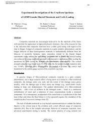
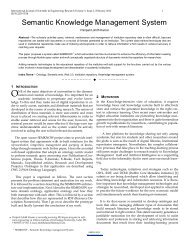
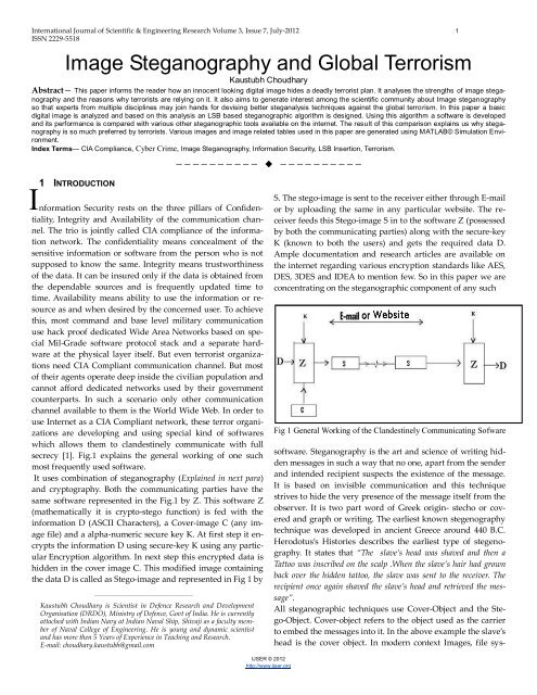
secrecy [1]. Fig.1 explains the general working of one such<br />
most frequently used software.<br />
It uses combination of steganography (Explained in next para)<br />
<strong>and</strong> cryptography. Both the communicating parties have the<br />
same software represented in the Fig.1 by Z. This software Z<br />
(mathematically it is crypto-stego function) is fed with the<br />
information D (ASCII Characters), a Cover-image C (any image<br />
file) <strong>and</strong> a alpha-numeric secure key K. At first step it encrypts<br />
the information D using secure-key K using any particular<br />
Encryption algorithm. In next step this encrypted data is<br />
hidden in the cover image C. This modified image containing<br />
the data D is called as Stego-image <strong>and</strong> represented in Fig 1 by<br />
————————————————<br />
Kaustubh Choudhary is Scientist in Defence Research <strong>and</strong> Development<br />
Organisation (DRDO), Ministry of Defence, Govt of India. He is currently<br />
attached with Indian Navy at Indian Naval Ship, Shivaji as a faculty member<br />
of Naval College of Engineering. He is young <strong>and</strong> dynamic scientist<br />
<strong>and</strong> has more then 5 Years of Experience in Teaching <strong>and</strong> Research.<br />
E-mail: choudhary.kaustubh@gmail.com<br />
S. The stego-image is sent to the receiver either through E-mail<br />
or by uploading the same in any particular website. The receiver<br />
feeds this Stego-image S in to the software Z (possessed<br />
by both the communicating parties) along with the secure-key<br />
K (known to both the users) <strong>and</strong> gets the required data D.<br />
Ample documentation <strong>and</strong> research articles are available on<br />
the internet regarding various encryption st<strong>and</strong>ards like AES,<br />
DES, 3DES <strong>and</strong> IDEA to mention few. So in this paper we are<br />
concentrating on the steganographic component of any such<br />
Fig 1 General Working of the Cl<strong>and</strong>estinely Communicating Sofware<br />
software. <strong>Steganography</strong> is the art <strong>and</strong> science of writing hidden<br />
messages in such a way that no one, apart from the sender<br />
<strong>and</strong> intended recipient suspects the existence of the message.<br />
It is based on invisible communication <strong>and</strong> this technique<br />
strives to hide the very presence of the message itself from the<br />
observer. It is two part word of Greek origin- stecho or covered<br />
<strong>and</strong> graph or writing. The earliest known stegenography<br />
technique was developed in ancient Greece around 440 B.C.<br />
Herodotus’s Histories describes the earliest type of stegenography.<br />
It states that “The slave’s head was shaved <strong>and</strong> then a<br />
Tattoo was inscribed on the scalp .When the slave’s hair had grown<br />
back over the hidden tattoo, the slave was sent to the receiver. The<br />
recipient once again shaved the slave’s head <strong>and</strong> retrieved the message”.<br />
All steganographic techniques use Cover-Object <strong>and</strong> the Stego-Object.<br />
Cover-object refers to the object used as the carrier<br />
to embed the messages into it. In the above example the slave’s<br />
head is the cover object. In modern context <strong>Image</strong>s, file sys-<br />
IJSER © 2012<br />
http://www.ijser.org
<strong>International</strong> <strong>Journal</strong> of Scientific & Engineering Research Volume 3, Issue 7, July-2012 2<br />
ISSN 2229-5518<br />
tems, audio, <strong>and</strong> video as well as HTML pages <strong>and</strong> even<br />
email-spams can be used as cover objects. Whereas stegoobject<br />
is the one which is carrying the hidden message. I.e. in<br />
the above example the ‘slaves head with fully grown hair <strong>and</strong> a<br />
hidden tattoo’ is acting as a stego-object. In the software mentioned<br />
above the Digital <strong>Image</strong> with hidden data is the stegoobject.<br />
<strong>Image</strong> steganalysis (finding out the information stored in the<br />
stego-image) is a challenging task. Analysis of the image requires<br />
complex mathematical <strong>and</strong> statistical operations to be<br />
performed on large three dimensional matrices <strong>and</strong> consumes<br />
very high computational power. Also we do not have any<br />
foolproof statistical <strong>and</strong> mathematical function capable of<br />
crisply differentiating the stego-image from bulk of innocent<br />
images flowing through the web every day. This identification<br />
of the steganographic signature in the stego-image is the most<br />
difficult part of any steganalysis algorithm. Somehow even if<br />
we identify the stego-image still the lack of knowledge of the<br />
stego-function (the algorithm which is converting cover-image<br />
into stego-image) makes the process of determining the hidden<br />
data very difficult as we do not know in what form <strong>and</strong> in<br />
which part of the stego-image the data is hidden. This makes<br />
image <strong>and</strong> video steganography the most favorite tool among<br />
the terrorist networks. It is said that Al-Qaeda has been using<br />
it long before 9/11 suicide attacks (September 11, 2001) [2] [3]<br />
[4]. In the software mentioned in Fig. 1 the secret message is<br />
hidden using Digital <strong>Image</strong> as the cover object. Thus before<br />
proceeding to <strong>Image</strong> <strong>Steganography</strong>, the analysis of the Digital<br />
<strong>Image</strong> in detail is a prerequisite.<br />
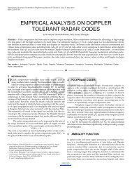
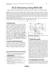
represents Pixel located at position (i,j) in the image. Then any<br />
image of dimensions m x n can be represented as matrix of<br />
Fig 2.b <strong>Image</strong> analyzed using Matlab<br />
pixels P(i,j) with i varying from 1 to m <strong>and</strong> j varying from 1 to<br />
n. Further each pixel P(i,j) is the combination of intensity levels<br />
of the Red, Green <strong>and</strong> Blue at the location (i,j) in the image.<br />
Also memory required for storing every pixel P(i,j) is the<br />
sum of memory required to store the intensity levels of Red,<br />
Green <strong>and</strong> Blue at the location (i,j). Mathematically every pixel<br />
P(i,j) = {R(i,j) ,G(i,j) ,B(i,j)} where R(i,j), G(i,j), B(i,j) represents<br />
the intensity levels of Red, Green <strong>and</strong> Blue colors at the location<br />
(i,j). In a 24 bit BMP image every pixel consumes 24 bits<br />
for storing the 8 bit color intensity levels of Red, Green <strong>and</strong><br />
Blue. Hence, all color variations are derived from the combination<br />
of these three colors <strong>and</strong> their varying intensity levels<br />
represented by 8 bits (where (00000000)2 corresponds to intensity<br />
of decimal 0 <strong>and</strong> (11111111)2 = 2 0 +2 1 +2 2 +2 3 +2 4 +2 5 +2 6 +2 7 corresponds<br />
to intensity level of decimal 255).<br />
2 DIGITAL IMAGE<br />
Every Digital <strong>Image</strong> consists of several smallest possible discrete<br />
picture elements known as Pixels. For better analysis of<br />
the digital image a very small 11 x 8 pixel 24 bit BMP <strong>Image</strong> [5]<br />
(image with 11 rows <strong>and</strong> 8 columns of pixels) has been created<br />
as shown in Fig 2.a. Since the image is too small for printing<br />
purposes so the same is enlarged by pixel spreading (Fig 2.a)<br />
<strong>and</strong> pixel enlargement (Fig 2.a). This image is analyzed using<br />
Matlab to produce detailed view of each pixel (shown as rectangular<br />
blocks) along with the row <strong>and</strong> column number of<br />
each pixel as given in Fig 2.b.<br />
Fig 2.a 24 bit 11 x 8 Pixel BMP <strong>Image</strong><br />
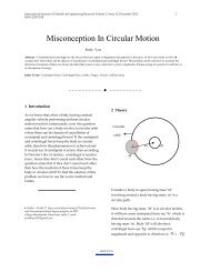
Each pixel is made up of combination of three primary colors-<br />
Red, Green <strong>and</strong> Blue. It is the combination of the varying intensity<br />
levels of these three primary colors which produces all<br />
other colors in the digital image. In Fig. 3 the same 11 x 8 pixel<br />
image is shown as combination of three primary colors. If P(i,j)<br />
IJSER © 2012<br />
http://www.ijser.org<br />
Fig 3 <strong>Image</strong> as Combination of Varying Intensity Levels of Three<br />
Primary Colors<br />
Thus any pixel can be combination of 256 different shades<br />
(ranging from intensity level of 0 to intensity level of 255) of<br />
red, green <strong>and</strong> blue resulting in 256 x 256 x 256 or more than<br />
16-million colors. Whole range of shades of Red, Green <strong>and</strong><br />
Blue varying from intensity level 255 to intensity level of 4 are<br />
shown in Fig 4. Intensity level of 0 in all three colors appears<br />
Black. Digital images are stored in a three-dimensional matrix<br />
format with row <strong>and</strong> column number corresponding to pixel
<strong>International</strong> <strong>Journal</strong> of Scientific & Engineering Research Volume 3, Issue 7, July-2012 3<br />
ISSN 2229-5518<br />
Fig 4 Range of Shades of Red, Green <strong>and</strong> Blue<br />
position. There are 3 unsigned 8 bit values (these values are in<br />
Binary format but for ease of representation they are shown in<br />
equivalent Decimal) at each pixel position (row-column). In<br />
Table 1.a, Table 1.b <strong>and</strong> Table 1.c the same 11 x 8 pixel 24 bit<br />
BMP <strong>Image</strong> is shown as 3 two-dimensional matrices corres-<br />
1 2 3 4 5 6 7 8<br />
1 255 0 0 0 255 255 255 255<br />
2 255 0 0 0 255 255 255 255<br />
3 255 0 255 0 255 255 255 255<br />
4 255 255 255 255 255 255 255 255<br />
5 255 0 0 0 255 255 255 0<br />
6 0 0 0 0 0 0 0 0<br />
7 255 0 0 0 255 255 255 0<br />
8 255 0 0 0 255 255 255 255<br />
9 255 0 0 0 255 255 255 0<br />
10 255 0 255 0 255 255 0 192<br />
11 128 0 255 0 128 255 192 0<br />
Table 1.a Matrix R showing Red value of each Pixel Position<br />
(Red Layer of the <strong>Image</strong>)<br />
1 2 3 4 5 6 7 8<br />
1 255 0 0 0 255 255 255 255<br />
2 255 255 0 255 255 255 255 255<br />
3 255 0 128 0 255 255 255 255<br />
4 255 255 128 255 255 255 255 255<br />
5 255 0 0 0 255 255 255 0<br />
6 0 0 0 0 0 0 0 0<br />
7 255 0 0 0 255 255 255 0<br />
8 255 0 0 0 255 255 255 255<br />
9 255 0 0 0 255 255 255 0<br />
10 255 0 255 0 255 255 0 192<br />
11 64 0 255 0 64 255 192 0<br />
Table 1.b Matrix G showing Green value of each Pixel Position<br />
(Green Layer of the <strong>Image</strong>)<br />
IJSER © 2012<br />
http://www.ijser.org<br />
1 2 3 4 5 6 7 8<br />
1 255 0 0 0 255 255 255 255<br />
2 255 255 0 255 255 255 255 255<br />
3 255 0 64 0 255 255 255 255<br />
4 255 255 64 255 255 255 255 255<br />
5 255 0 0 0 255 255 255 128<br />
6 128 0 0 0 128 128 128 128<br />
7 255 0 0 0 255 255 255 128<br />
8 255 0 0 0 255 255 255 255<br />
9 255 0 0 0 255 255 255 0<br />
10 255 0 255 0 255 255 0 192<br />
11 0 0 255 0 0 255 192 0<br />
Table 1.c Matrix B showing Blue value of each Pixel Position<br />
(Blue Layer of the <strong>Image</strong>)<br />
ponding to Red, Green <strong>and</strong> Blue intensity levels respectively.<br />
For instance element present in the first row <strong>and</strong> first column<br />
of this image matrix (E(1,1)) contains 255,255,255 as its RGB<br />
values. So any element located at i th row <strong>and</strong> j th column of the<br />
image matrix will be now onwards represented by E(i,j) in this<br />
entire paper. Further every element E(i,j) contains 3 more elements<br />
R(i,j), G (i,j) <strong>and</strong> B(i,j) jointly known as RGB value of<br />
any arbitrary pixel (i,j).<br />
3 IMAGE STEGANOGRAPHY<br />
We have just explored that in a 24 bit BMP image every pixel<br />
occupies 24 bits or 3 Bytes. Out of these 24 bits each of the<br />
three primary colors occupies 8 bits. These 8 bits carry the respective<br />
color intensity levels at any given pixel. Hence<br />
amount of color information carried by two least significant<br />
bits (LSB) is 4 color levels ((00000000), (00000001), (00000010)<br />
<strong>and</strong> (00000011) corresponding to intensity levels of 0, 1, 2 <strong>and</strong><br />
3 respectively) out of 256 possible color levels. Thus if the last<br />
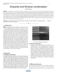
two bits are changed the pixel will have minimal degradation<br />
of 4/256 or 1.5625%.This minor degradation is psycho-visually<br />
imperceptible. Marginal alteration of color intensity (from intensity<br />
level of 255 to 250) is shown in the Fig 5 which proves<br />
that such minor changes are totally imperceptible to human<br />
eye due to limitations in Human Visual System (HVS) [6].<br />
But at the cost of this negligible degradation we get 6 bits (2<br />
bits each from red, green <strong>and</strong> blue) out of every pixel for<br />
transmitting our secret data. Although a general ASCII st<strong>and</strong>ard<br />
requires 7 bits for storing a character. But even with 6 bits<br />
we can produce (000000 = 0 to 111111=63) 64 symbols. In English<br />
language we have only 26 alphabets. So even after mapping<br />
every 6 bit code to a particular English alphabet (small<br />
letters) we are still left with 38 more 6 bit binary symbols. 36<br />
out of them can be used for representing normal day to day<br />
common symbols like !@$%^&*(){}?,+= - ‚ SPACE etc. While 2<br />
of them (111110 <strong>and</strong> 111111) are reserved for two special purposes<br />
<strong>and</strong> here onwards will be referred as special symbols.
<strong>International</strong> <strong>Journal</strong> of Scientific & Engineering Research Volume 3, Issue 7, July-2012 4<br />
ISSN 2229-5518<br />
The encoding algorithm (algorithm for embedding data in<br />
cover-image) will operate over the image, pixel by pixel <strong>and</strong><br />
embeds character in one pixel at a time. Once all the characters<br />
are embedded in the image the special symbol 111111 is inserted<br />
in the immediate next pixel (i.e. the pixel immediately<br />
next to the one containing the last input character. This helps<br />
the decoding algorithm (algorithm for extracting data from<br />
stego-image) by informing it to stop reading the image from<br />
next pixel onwards as no more data is embedded in further<br />
pixels. We call such a character Terminator Character `Tr’ <strong>and</strong><br />
represent it by 111111. Also due to limitations imposed by 6<br />
bits we were unable to make provisions for capital letters. So<br />
we use a special character which when follows any normal<br />
character implies that it was in Capitals. We call it Capitals character<br />
‘Cl’ <strong>and</strong> represent it by 111110.<br />
Character Binary<br />
Symbol<br />
d 000100<br />
e 000101<br />
h 001000<br />
l 001001<br />
o 001111<br />
r 010010<br />
w 010111<br />
‚ 111100<br />
SPACE 000000<br />
`Tr’ (Termination) 111111<br />
Table 2 Characters <strong>and</strong> their Codes<br />
We are using our same old 11 x 8 BMP image for storing string<br />
“hello world”. The code used for representing these 9 characters<br />
(d, e, h, l,o, r, w, ‚, SPACE) is shown in Table 2. In Fig 6 the<br />
stego-image generated after embedding the string is shown as<br />
combination of 3 primary colors. This stego-image is shown as<br />
3 two-dimensional matrices in Table 3.a, Table 3.b <strong>and</strong> Table<br />
3.c correspond ing to red, green <strong>and</strong> blue layers respectively.<br />
Fig 5 Marginal alteration of Intensity Levels<br />
Now if we compare Table 1 with Table 3 then we see that only<br />
first two rows have changed. For instance RGB values of element<br />
E(1,1) is modified from 255, 255, 255 (Table 1) into<br />
255,255,252 (Table 3). This is because binary code of first<br />
Fig 6 Stego-<strong>Image</strong> (string “hello world” embedded) as combination<br />
of Three Primary Colors<br />
ROW<br />
1 2 3 4 5 6 7 8<br />
1 255 0 0 0 252 252 252 253<br />
2 252 1 0 0 255 255 252 252<br />
3 255 0 255 0 255 255 255 255<br />
4 255 255 255 255 255 255 255 255<br />
5 255 0 0 0 255 255 255 0<br />
6 0 0 0 0 0 0 0 0<br />
7 255 0 0 0 255 255 255 0<br />
8 255 0 0 0 255 255 255 255<br />
9 255 0 0 0 255 255 255 0<br />
10 255 0 255 0 255 255 0 192<br />
11 128 0 255 0 128 255 192 0<br />
Table 3.a Matrix R’ showing Red value of each Pixel<br />
Position in the Stego-<strong>Image</strong> containing ‚hello world‛<br />
ROW<br />
1 2 3 4 5 6 7 8<br />
1 255 2 1 3 255 255 252 253<br />
2 255 252 3 253 255 255 252 252<br />
3 255 0 128 0 255 255 255 255<br />
4 255 255 128 255 255 255 255 255<br />
5 255 0 0 0 255 255 255 0<br />
6 0 0 0 0 0 0 0 0<br />
7 255 0 0 0 255 255 255 0<br />
8 255 0 0 0 255 255 255 255<br />
9 255 0 0 0 255 255 255 0<br />
10 255 0 255 0 255 255 0 192<br />
11 64 0 255 0 64 255 192 0<br />
Table 3.b Matrix G’showing Green value of each Pixel<br />
Position in the Stego-<strong>Image</strong> containing ‚hello world‛<br />
ROW<br />
1 2 3 4 5 6 7 8<br />
1 252 0 1 0 252 255 252 255<br />
2 255 254 0 252 252 255 252 252<br />
3 255 0 64 0 255 255 255 255<br />
4 255 255 64 255 255 255 255 255<br />
5 255 0 0 0 255 255 255 128<br />
6 128 0 0 0 128 128 128 128<br />
7 255 0 0 0 255 255 255 128<br />
8 255 0 0 0 255 255 255 255<br />
9 255 0 0 0 255 255 255 0<br />
10 255 0 255 0 255 255 0 192<br />
11 0 0 255 0 0 255 192 0<br />
Table 3.c Matrix B’ showing Blue value of each Pixel<br />
Position in the Stego-<strong>Image</strong> containing ‚hello world‛<br />
IJSER © 2012<br />
http://www.ijser.org
<strong>International</strong> <strong>Journal</strong> of Scientific & Engineering Research Volume 3, Issue 7, July-2012 5<br />
ISSN 2229-5518<br />
character “ of the string “hello world” is 111100 (Table 2). So<br />
values 11, 11, 00 are inserted as the last two LSB of R(1,1),<br />
G(1,1) <strong>and</strong> B(1,1) respectively.Since R(1,1) <strong>and</strong> G(1,1) already<br />
contained 255 or (11111111)2 so no change has occurred in<br />
them. As G(1,1) also contained 255 but the value to be inserted<br />
in its LSB was 00 so the new value stored by G(1,1) is 252 or<br />
(11111100)2. Similarly RGB value of E(1,2) is changed from<br />
0,0,0 to 0,2,0 for embedding character `h’ given by code 001000.<br />
Similarly all other characters of the string are embedded. Only<br />
first two rows have changed because only 14 characters are<br />
inserted: 13 (length of ‚hello world‛) + 1 (Terminator Character).<br />
Each row contains 8 elements so only two rows are consumed<br />
for embedding data. At 14 th pixel (in row major order)<br />
represented by element E(2,6) the terminator character (given<br />
by code 111111) is embedded after which character insertion<br />
stops from next row onwards .<br />
4 ALGORITHM FOR STEGANOGRAPHY<br />
IJSER © 2012<br />
http://www.ijser.org<br />
Any pixel P(i,j) consists of 3 eight bit RGB values R(i,j), G(i,j)<br />
<strong>and</strong> B(i,j). For insertion of data we are modifying only the last<br />
two LSBs of this eight bit number. Let this eight bit number be<br />
represented by K in decimal format <strong>and</strong> k8k7k6k5k4k3k2k1 in<br />
binary format. Hence (K)DECIMAL or simply K =<br />
(k8k7k6k5k4k3k2k1)2 is one of the RGB values for any arbitrary<br />
pixel P(i,j). Mathematically k1 = K modulo 2 <strong>and</strong><br />
k2 = (K/2) modulo 2. For embedding the character the two<br />
LSBs k2 <strong>and</strong> k1 are replaced by 2 other bits c2 <strong>and</strong> c1 respectively<br />
as per the character’s code (Table 2).<br />
This algorithm is based on a simple principle of number<br />
theory. When any natural number is added or subtracted by 1<br />
then the least significant bit of its binary equivalent gets<br />
flipped. Also when a natural number is added or subtracted<br />
by 2 then the second least significant bit of its binary equivalent<br />
gets flipped. We can extract k1 <strong>and</strong> k2 from K by performing<br />
modulo operation on K. Once we know k1 <strong>and</strong> K2 then<br />
they can be compared with c1 <strong>and</strong> c2 <strong>and</strong> accordingly action<br />
may be taken. If they are same no action is required. Else for<br />
flipping k2 we need to subtract 2 from K <strong>and</strong> for flipping k1 we<br />
have to subtract 1 from K.<br />
Although subtraction will serve our purpose but this will shift<br />
the RGB intensity of the pixels in only one direction (negative<br />
side). Which means the new RGB value for the pixel P(i,j) =<br />
{R(i,j),G(i,j),B(i,j)} after embedding the data can be one of these<br />
R(i,j), R(i,j)-1, R(i,j)-2, R(i,j)-3 (Possible R values); G(i,j), G(i,j)-1,<br />
G(i,j)-2 , G(i,j)-3 (Possible G values) <strong>and</strong> B(i,j), B(i,j)-1, B(i,j)-2 ,<br />
B(i,j)-3 (Possible B values). This negative shift of R, G <strong>and</strong> B<br />
levels may make the stego-image relatively easier to be identified<br />
by the steganalyst. So for harboring the benefit of obscurity<br />
by r<strong>and</strong>omization we should simultaneously use addition<br />
also. The combination of addition <strong>and</strong> subtraction will more<br />
r<strong>and</strong>omize the image <strong>and</strong> make it more difficult to steganalyse.<br />
By using combination of addition <strong>and</strong> subtraction the<br />
possible RGB values for Pixel P(i,j) are R(i,j)-1, R(i,j)-2, R(i,j)-3,<br />
R(i,j), R(i,j)+1, R(i,j)+2, R(i,j)+3 (Possible R values); G(i,j)-1,<br />
G(i,j)-2, G(i,j)-3, G(i,j), G(i,j)+1, G(i,j)+2, G(i,j)+3 (Possible G values)<br />
<strong>and</strong> B(i,j)-1, B(i,j)-2, B(i,j)-3, B(i,j), B(i,j)+1, B(i,j)+2, B(i,j)+3<br />
(Possible B values).<br />
Also the addition in the intensity level of one color <strong>and</strong> simultaneous<br />
subtraction of the intensity level of another color at<br />
the same pixel will conserve the brightness of the pixel. This is<br />
because the gray scale intensity of the colored image is obtained<br />
by weighted average of its R, G <strong>and</strong> B values. As we<br />
know that for gray scale conversion the weight of G is highest<br />
among R, G, B so we will get the best results if we use subtraction<br />
in R <strong>and</strong> B <strong>and</strong> addition in G.<br />
But imprudent use of addition or subtraction for LSB replacement<br />
may cause error in certain bright or dark pixels by either<br />
raising the color intensity levels above 255 or reducing it below<br />
0 respectively. To overcome such limitations an algorithm<br />
is developed which performs addition by 1 when k1 is 0 <strong>and</strong><br />
addition by 2 when k2 is 0. On the other h<strong>and</strong> it subtracts by 1<br />
when k1 is 1 <strong>and</strong> subtracts by 2 when k2 is 1. The pseudo-code<br />
of this algorithm for LSB replacement is given in the boxes<br />
below (Box 1 <strong>and</strong> Box 2). It is based on two IF-ELSE control<br />
structures. Box 1 explains how c2 replaces k2 <strong>and</strong> Box 2 explains<br />
how c1 replaces k1.<br />
IF (k 2 = = 1)<br />
IF (c 2 = = 0)<br />
K = K-2;<br />
ENDIF<br />
ELSE<br />
IF (c 2 = = 1)<br />
K = K+2;<br />
ENDIF<br />
ENDIF<br />
Box1 LSB Replacement of c 2 Box2 LSB Replacement of c 1<br />
5 PERFORMANCE EVALUATION<br />
IF (k 1 = =1)<br />
IF (c 1 = = 0)<br />
K = K-1;<br />
ENDIF<br />
ELSE<br />
IF (c 1 = = 1)<br />
K = K+1;<br />
ENDIF<br />
ENDIF<br />
Based on above algorithm, software was developed in MAT-<br />
LAB©. It was compared with three other free steganography<br />
softwares available on the Internet (Our Secret, Eureka Steganographer<br />
<strong>and</strong> Quick Stego). Then all four of them were examined<br />
using StegSpy 2.1 (the only steganalytic tool easily <strong>and</strong><br />
feely available on the net downloaded from location<br />
http://www.spy-hunter.com/stegspydownload.htm).It claimed<br />
to identify signatures of well acclaimed stego-tools like Hiderman,<br />
JPHide<strong>and</strong>Seek, Masker, JPegX <strong>and</strong> Invisible Secrets.<br />
But it was unable to identify any data in the stego-images generated<br />
by all the four test software. On the contrary it found a<br />
hiderman’s signature in one of the cover image itself (a world<br />
map obtained from internet). The preliminary comparison<br />
results are summarized in Table 4. This table also contains
<strong>International</strong> <strong>Journal</strong> of Scientific & Engineering Research Volume 3, Issue 7, July-2012 6<br />
ISSN 2229-5518<br />
Name of the <strong>Steganography</strong><br />
Software<br />
Algorithm<br />
(Section 4 )<br />
Our Secret<br />
Eureka Steganograper<br />
(Stegan2)<br />
QuickStego by Quick<br />
Crypto<br />
<strong>Image</strong> Type BMP 24 bit All file types(even doc,<br />
text & media files) except<br />
.TIFF<br />
All common image types<br />
except .TIFF<br />
BMP , JPEG , JPG <strong>and</strong><br />
GIF<br />
Interface CUI GUI GUI GUI<br />
Minimum <strong>Image</strong> Size<br />
required for storing a<br />
single character (For<br />
BMP <strong>Image</strong>)<br />
2 Pixel <strong>Image</strong><br />
or 62 Bytes<br />
1 Pixel <strong>Image</strong> or 58<br />
Bytes.<br />
59 Pixels or 230 Bytes 75 Pixels or 282 Bytes<br />
Number<br />
of character<br />
stored in<br />
24 Bit<br />
BMP<br />
image of<br />
lower<br />
case<br />
char<br />
Upper<br />
case<br />
char<br />
Case of the character<br />
makes no difference<br />
Case of the character<br />
makes no difference<br />
Case of the character<br />
makes no difference<br />
100 Pixels 99 49 Infinite characters 25 characters 9 characters<br />
1000 Pixels 999 499 Infinite characters 607 characters 331 characters<br />
10000 Pixel 9999 4999 Infinite characters 6411 characters 3516 characters<br />
Insertion Algorithm<br />
2 bit LSB insertion<br />
(SDT)<br />
Uses file systems.<br />
1 Bit LSB Insertion<br />
(SDT)<br />
Other Features<br />
Other then characters it<br />
can embed all types of<br />
files also.<br />
Supports data encryption.<br />
Supports data encryption.<br />
Comments<br />
It can store large file or<br />
thous<strong>and</strong>s of characters<br />
in 1 pixel by increasing<br />
the memory size of the<br />
pixel.<br />
Crashes after few runs.<br />
If information compared to<br />
image is very long (Eg: In<br />
100 pixel image if more<br />
than 19 characters inserted)<br />
then the stego-image generated<br />
is of unrecognized<br />
format <strong>and</strong> is not readable.<br />
Crashes after few runs.<br />
Steganalysis by StegSpy<br />
2.1<br />
Could not detect Could not detect Could not detect Could not detect<br />
Web Source<br />
Not Uploaded<br />
Yet<br />
http://www.securekit.net/<br />
oursecret.htm<br />
http://www.brothersoft.co<br />
m/eureka-steganographerv2-266233.html<br />
http://quickcrypto.com/f<br />
ree-steganographysoftware.html<br />
Table 4<br />
Comparative Study of Different Stego Tools<br />
the web source from where these softwares were downloaded.<br />
Among all the four softwares the Eureka steganographer behaved<br />
in most weird manner. As mentioned in Table 4 using it<br />
we can embed 25 characters in a 100 pixel image but whenever<br />
more than 19 characters were inserted it produced an unrecognized<br />
file format (from which we can retrieve data). But<br />
this number (19 characters) was not fixed <strong>and</strong> varied with<br />
every trial. In certain trials it produced an unrecognizable stego-file<br />
even when 1 character was inserted in the same 100<br />
pixel image.<br />
5.1. Susceptibility to Steganalysis<br />
As mentioned in the Introduction the Steganalysis is a difficult<br />
task but still we cannot completely rule out its probability.<br />
Probabilistically every stego-image is susceptible to such an<br />
attack. To minimize this probability we have to keep differences<br />
between the cover-image <strong>and</strong> stego-image very smooth<br />
<strong>and</strong> as small as possible.<br />
IJSER © 2012<br />
http://www.ijser.org
<strong>International</strong> <strong>Journal</strong> of Scientific & Engineering Research Volume 3, Issue 7, July-2012 7<br />
ISSN 2229-5518<br />
For determining the susceptibility to steganalysis these four<br />
stego-tools were evaluated by three different techniques. In all<br />
these three test runs the difference between the cover-image<br />
<strong>and</strong> stego-image was calculated using various statistical parameters.<br />
In first two modes our same old 11 x 8 pixel BMP<br />
image was used for embedding the data. In first case only 4<br />
characters (abcd) were inserted in it whereas in the second case<br />
the stego-softwares were evaluated at full capacity. I.e. maximum<br />
possible characters which these tools allowed to insert in<br />
this 11 x 8 pixel image. In third case a large image (300 x 300<br />
pixel BMP image) was used for embedding 600 characters<br />
(abc...z1234 in repetition 20 times).<br />
5.1.1 Parameters for Measurement of Susceptibility to<br />
Steganalysis<br />
The various parameters used for calculating the difference<br />
between the cover-image <strong>and</strong> stego-image are Mean Difference<br />
(MD), Mean Absolute Difference (MAD), St<strong>and</strong>ard Deviation<br />
of the Difference (STD) <strong>and</strong> Range of Difference<br />
(Z = Zupper - Zlower), number of pixels changed (P) <strong>and</strong> change in<br />
the size of the image (in terms of memory occupied) K. These<br />
parameters are explained below.<br />
Let cover-image be represented by C <strong>and</strong> stego-image be<br />
represented by S. Then cover image C <strong>and</strong> stego-image S consists<br />
of three RGB components CR, CG, CB <strong>and</strong> SR, SG, SB respectively.<br />
Thus the difference image D = C – S also consists of<br />
three RGB components DR = CR – SR; DG = CG – SG <strong>and</strong> DB = CB –<br />
SB. Similarly all these statistical parameters have three components<br />
corresponding to R, G <strong>and</strong> B.<br />
Three components of Mean Difference MD given as MDR,<br />
MDG <strong>and</strong> MDB are arithmetic means of DR, DG <strong>and</strong> DB respectively.<br />
But this parameter does not gives us the exact idea of<br />
the difference between the two images as the negative <strong>and</strong><br />
positive values in the matrix DR ,DG <strong>and</strong> DB cancel each other.<br />
To overcome this drawback another parameter Mean Absolute<br />
Difference (MAD) is introduced. For three color components it<br />
is represented as MADR, MADG <strong>and</strong> MADB <strong>and</strong> corresponds to<br />
arithmetic mean of the absolute values of quantities in DR, DG<br />
<strong>and</strong> DB respectively. But in order to determine the degree of<br />
abrupt variations in RGB components of cover-image C <strong>and</strong><br />
stego-image S the St<strong>and</strong>ard Deviation (STD) of the difference<br />
matrices DR, DG <strong>and</strong> DB is computed <strong>and</strong> represented as STDR,<br />
STDG <strong>and</strong> STDB. The STD is measure of sudden sharp changes<br />
between C <strong>and</strong> S (Spikes or Grains in difference image<br />
D = C - S).<br />
In addition we have used other parameters like Range of difference<br />
in D given by ZR, ZG <strong>and</strong> ZB where ZR = ZR upper - ZR lower.<br />
ZR upper is maximum value in DR <strong>and</strong> ZR lower is minimum value in<br />
DR. Similarly we can compute ZG <strong>and</strong> ZB. We have incorporated<br />
one more parameter to measure the spread of the difference<br />
<strong>and</strong> it is given by no of pixels changed in R, G <strong>and</strong> B<br />
components of the image <strong>and</strong> given as PR, PG <strong>and</strong> PB. Parameter<br />
K is used for determining the difference between the memory<br />
size of C <strong>and</strong> S.<br />
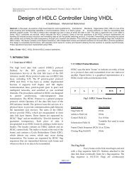
5.1.2 Results of three Trials<br />
These parameters as outcomes of the three trials are illustrated<br />
in Table 5.a, Table 5.b <strong>and</strong> Table 5.c. From these tables it can be<br />
very clearly deduced that for N character input the algorithm<br />
developped in Section 4 modifies N+1 pixels, Eureka steganographer<br />
tentatively modifies 0.3353N + 1.8096 pixels whereas<br />
Quick Stego modifies 1.534N + 39.5963 pixels. Further it’s<br />
worth mentioning that Oursecret’s algorithm does not modify<br />
any pixel but it increases the size (in terms of memory) of cover-image<br />
file. Thus we can see that Eureka concentrates the<br />
entire information in few pixels where as Quick Stego <strong>and</strong><br />
algorithm (Section 4) evenly distributes the information in<br />
larger number of pixels. This explains why Eureka steganographer<br />
has highest St<strong>and</strong>ard Deviation STD <strong>and</strong> Range Z. As<br />
a result of this high STD <strong>and</strong> Z, the stego-images generated by<br />
Eureka has grains <strong>and</strong> spikes as shown in Figure 7.<br />
Algorithm<br />
(Section 4 )<br />
Our Secret<br />
Eureka Steganographer<br />
(Stegan 2)<br />
QuickStego<br />
Quick Crypto<br />
Software MD MAD STD Z lower Z upper Z P K<br />
by<br />
Red 0.1364 0.1364 0.6285 0 3 3 5 Pixels 0<br />
Green 0.1250 0.1477 0.6399 -1 3 4 5 Pixels<br />
Blue 0.0682 0.1818 0.7078 -3 3 6 5 Pixels<br />
Red 0 0 0 0 0 0 0 Pixels<br />
Green 0 0 0 0 0 0 0 Pixels 212 Bytes<br />
Blue 0 0 0 0 0 0 0 Pixels<br />
Red 4.7273 4.7273 28.1750 0 217 217 3 Pixels 0<br />
Green - 0.2614 3.7841 21.8519 -118 155 273 3 Pixels<br />
Blue 5.8409 5.8409 31.4134 0 193 193 3 Pixels<br />
Red 0.3068 0.5114 0.6496 -1 1 2 45 Pixels 0<br />
Green - 0.0682 0.4773 0.6914 -1 1 2 42 Pixels<br />
Blue -0.0795 0.3523 0.5915 -1 1 2 31 Pixels<br />
Table 5.a 4 Characters Inserted in 11 x 8 Pixel <strong>Image</strong><br />
IJSER © 2012<br />
http://www.ijser.org
<strong>International</strong> <strong>Journal</strong> of Scientific & Engineering Research Volume 3, Issue 7, July-2012 8<br />
ISSN 2229-5518<br />
Software MD MAD STD Z lower Z upper Z P K<br />
Algorithm<br />
Red 0.9886 1.6023 1.7053 -3 3 6 88 Pixels 0<br />
(Section 4 )<br />
Green 0.1818 1.5227 1.8417 -3 3 6 88 Pixels<br />
(87 Characters) Blue 0.0909 1.4318 1.8044 -3 3 6 88 Pixels<br />
Our Secret<br />
Red 0 0 0 0 0 0 0 Pixels<br />
(300 Characters)<br />
Green 0 0 0 0 0 0 0 Pixels<br />
252Bytes<br />
Eureka Steganographer<br />
(Stegan 2)<br />
(18 Characters)<br />
Blue 0 0 0 0 0 0 0 Pixels<br />
Red 4.0568 10.0114 40.2893 -162 217 379 8 Pixels 0<br />
Green 1.3977 10.1705 39.6492 -207 193 400 8 Pixels<br />
QuickStego<br />
Quick Crypto<br />
(5 characters)<br />
by<br />
Blue 4.3409 8.9091 37.3867 -110 246 356 7 Pixels<br />
Red 0.3182 0.5455 0.6703 -1 1 2 48 Pixels 0<br />
Green -0.0795 0.5114 0.7147 -1 1 2 45 Pixels<br />
Blue -0.0909 0.3636 0.5995 -1 1 2 32 Pixels<br />
Table 5.b Full Capacity Evaluation of Softwares Using 11 x 8 Pixel <strong>Image</strong><br />
Algorithm<br />
(Section 4 )<br />
Our Secret<br />
Eureka Steganographer<br />
(Stegan 2)<br />
Software MD MAD STD Z lower Z upper Z P K<br />
Red 0.0112 0.0139 0.1737 -2 3 5 601 Pixels 0<br />
Green 0.0057 0.0132 0.1664 -3 3 6 601 Pixels<br />
Blue 0.0032 0.0131 0.1677 -3 3 6 601 Pixels<br />
Red 0 0 0 0 0 0 0 Pixels<br />
Green 0 0 0 0 0 0 0 Pixels<br />
Blue 0 0 0 0 0 0 0 Pixels<br />
Red -0.1508 0.1994 5.2088 -240 198 438 201 Pixels 0<br />
Green -0.0972 0.1880 4.8514 -239 193 432 203 Pixels<br />
252<br />
Bytes<br />
QuickStego<br />
Quick Crypto<br />
by<br />
Blue -0.2655 0.2818 7.1111 -253 149 402 202 Pixels<br />
Red 0.0038 0.0103 0.1012 -1 1 2 923 Pixels 0<br />
Green -0.0020 0.0103 0.1013 -1 1 2 924 Pixels<br />
Blue -0.0043 0.0074 0.0860 -1 1 2 668 Pixels<br />
Table 5.c<br />
600 Characters Inserted in 300 x 300 Pixel <strong>Image</strong><br />
Fig 7 Grains in the Stego-<strong>Image</strong> <strong>and</strong> Difference-<strong>Image</strong> using<br />
Eureka Steganographer<br />
For all other three softwares (Algorithm mentioned in Section<br />
IJSER © 2012<br />
http://www.ijser.org<br />
4, Quick Stego <strong>and</strong> Our Secrets) the difference between Cover<br />
<strong>Image</strong> <strong>and</strong> Stego <strong>Image</strong> is so low that it is visually imperceptible<br />
to find any change. So the difference between the two can<br />
only be established using the statistical parameters mentioned<br />
in section 5.1.1 Further the range Z of Quick Stego is always<br />
fixed between -1 <strong>and</strong> 1. This implies that it uses 1 bit LSB insertion.<br />
Since the algorithm mentioned in section 4 uses last 2<br />
bit LSB insertion so the overall range lies is between -3 <strong>and</strong> 3.<br />
Further we had calculated (Section 3) that the maximum degradation<br />
which may occur in the image after 2 bit LSB insertion<br />
in every pixel will be 1.5625%. But the real error was<br />
much lower. The average of the Mean Absolute Diffrences<br />
(MAD) for the algorithm mentioned in section 4 in all the<br />
three tables i.e. Table 5.a, Table 5.b <strong>and</strong> Table 5.c came out to<br />
be 0.565244 intensity levels out of 256 possible intensity levels.<br />
In percentage terms this difference was just 0.22701% which is<br />
much lower than 1.5625%. Similarly for Eureka Steganographer<br />
average MAD was found out to be 4.901389 intensity levels<br />
or 1.9146% difference whereas for Quick Stego it was just<br />
0.30994 Intensity Levels or 0.12854% diffrence.
<strong>International</strong> <strong>Journal</strong> of Scientific & Engineering Research Volume 3, Issue 7, July-2012 9<br />
ISSN 2229-5518<br />
Thus we see that Quick Stego has less data embedding capacity<br />
<strong>and</strong> it is least susceptible to general steganlytic attack<br />
among all four. Our Secret does not modify the image because<br />
it changes the memory allocation in the file system but it is<br />
susceptible to steganalytic attack as the file size increases. Algorithm<br />
mentioned in section 4 has large information carrying<br />
capacity but it is more susceptible to attacks then Quick Stego.<br />
Eureka is always an easy prey for most steganalysts.<br />
5.2 Steganlysis<br />
Before we begin with steganalysis we should know various<br />
communication channels <strong>and</strong> techniques through which these<br />
stego-images are being used by terrorist organizations <strong>and</strong><br />
secondly the reasons why they are relying on it so much.<br />
5.2.1 Channels <strong>and</strong> Techniques used by Terrorist organizations<br />
As mentioned in the introduction, for any communication<br />
channel meeting CIA Compliance is must. To achieve it terrorists<br />
are using stego-images for one to one communication via<br />
e-mails. On the other h<strong>and</strong> these stego-images are used as<br />
Electronic Dead Drops [7][8][9][10]. Dead drop is a Cold Warera<br />
slang connoting a place (like a common letter box or a<br />
common book in a public library) where spies left information.<br />
It helped the two communicating parties to avoid direct meeting<br />
or knowing each other. Thus it provided advantages of<br />
anonymity. On similar lines the terrorists upload stego-images<br />
in a public forum (eg Online Auction site E-Bay) <strong>and</strong> thus keep<br />
communicating without knowing each other. [7][11][12][13].<br />
There does not exist any coordination, meetings, E-mail or<br />
instant messaging between them. All that exists is a picture<br />
posted to a public forum, <strong>and</strong> then downloaded by anyone<br />
sufficiently enticed by the subject line of the image (even third<br />
parties can download the image). But images posted in the<br />
forums not only serve as electronic dead drops but can also be<br />
used for broadcasting the secret message globally to all the<br />
agents operating in different geographical regions. Thus it<br />
facilitates completely anonymous <strong>and</strong> asynchronous communication.<br />
Also these stego-images are used by terrorists for<br />
safely carrying <strong>and</strong> storing secret information hidden in normal<br />
appearing videos <strong>and</strong> <strong>Image</strong>s in their personal computers<br />
<strong>and</strong> memory cards[1][2].<br />
5.2.1 Advantages offered by <strong>Steganography</strong><br />
A legitimate company never needs to use dead drops. But the<br />
terrorists need it. Thus the very aspect of secrecy makes it a<br />
potent tool in terrorists’ h<strong>and</strong>. The main reason for using steganography<br />
is the cost of inserting the data in the image is far<br />
lower than the cost of detecting even the presence of data in<br />
the same-stego image. In some cases it may even be impossible<br />
to detect any presence of data. For instance, a one bit, ‚yes‛ or<br />
‚no‛ message embedded in a big image file would be nearly<br />
IJSER © 2012<br />
http://www.ijser.org<br />
impossible to find [14]. Moreover these image files could be<br />
easily converted into video files <strong>and</strong> collages <strong>and</strong> can make<br />
detection even more difficult.<br />
The smaller the size of information, the harder it is to find.<br />
This can be numerically established by comparing MAD <strong>and</strong><br />
STD fields of Table 5.a with Table 5.b. The average St<strong>and</strong>ard<br />
Deviation of the Difference (STD) for all three softwares (our<br />
secret is not considered because it has different insertion mechanism)<br />
is 9.48332 intensity levels when only 4 characters are<br />
embedded (Table 5.a) whereas it is 13.85123 intensity levels<br />
when all the three softwares were evaluated at full capacity<br />
(inserting 36.67 characters on an average) (Table 5.b). For the<br />
same two sets of observation the average Mean Absolute Difference<br />
(MAD) is 1.795467 intensity levels <strong>and</strong> 3.896478 Intensity<br />
Levels respectively.<br />
Further the lack of knowledge of insertion algorithm makes<br />
detection even difficult. Even after detection the extraction of<br />
data is another herculean task. For instance algorithm mentioned<br />
in section 4 inserts a character at every pixel by using 6<br />
bits in each pixel. But use of 6 bits for representing a character<br />
is not a st<strong>and</strong>ard ASCII method for denoting a character. Further<br />
this algorithm reads the pixel continuously in row major<br />
order. Some other algorithm may do it by combining Row Major,<br />
Column Major <strong>and</strong> even diagonal order <strong>and</strong> may read pixels<br />
in any other pattern.<br />
Most alarming is the fact that this algorithm (section 4) is<br />
based on one of the simplest image steganographic techniques<br />
(Spatial Domain <strong>Steganography</strong> based on changing the pixels<br />
through LSB Insertion) <strong>and</strong> still it can have so many variants.<br />
But the real steganographic algorithm used by terrorists is<br />
much more complex <strong>and</strong> will be using combination of multiple<br />
steganographic techniques like Transformation Domain<br />
<strong>Steganography</strong>[15] (Discrete Cosine Transforms as used in<br />
JPEG <strong>Image</strong>s, Discrete Wavelet Transform or even Fast Fourier<br />
Transform for embedding information in the transform domain<br />
of the image signal), Spread Spectrum <strong>Steganography</strong><br />
[16] (evenly spreading the information over entire image i.e.<br />
reducing the Steganographic Signal to Noise Ratio to minimum<br />
possible levels) or may use a different color space itself<br />
(Example RGB may be converted to YCbCr) <strong>and</strong> various other<br />
techniques [17].<br />
Another difficulty in image steganography is analysis of the<br />
image. This requires various mathematical <strong>and</strong> statistical operations<br />
to be performed on large three dimensional image<br />
matrices. This consumes very high computation power <strong>and</strong> is<br />
almost impossible to be performed for every image in the cyber<br />
space.<br />
5.2.2 Steganalysis<br />
Identifying a stego-image using visual clues is almost impossible.<br />
Among all the four test softwares only the Eureka software<br />
produced visually perceptible grains. That too we could
<strong>International</strong> <strong>Journal</strong> of Scientific & Engineering Research Volume 3, Issue 7, July-2012 10<br />
ISSN 2229-5518<br />
locate only after subtracting the stego-image from coverimage.<br />
Also in section 5 we saw that steganlysis software Stegspy<br />
2.1 was unable to detect any presence of information in<br />
any of the trials. This was because it was designed for detecting<br />
particular steganographic signatures which was considerably<br />
different from the one used in any of the four softwares.<br />
Unfortunately we have plethora of steganographic softwares<br />
[18] <strong>and</strong> algorithms [17] <strong>and</strong> thus detection becomes even<br />
more difficult.<br />
Most steganalysis algorithms can be broadly classified in to<br />
three types. Passive Steganalysis (only detection of steganographic<br />
signatures), Active Steganalysis (detection followed by<br />
extraction of data from the stego-image) <strong>and</strong> Active Warden<br />
(detection followed by destruction of the hidden information<br />
or embedding counter-information) [19].<br />
As mentioned in section 5.2.1 these stego-images are either<br />
being uploaded in the Public forums or they are being used<br />
for one to one communication through e-mails <strong>and</strong> by carrying<br />
them personally. If public forums are used then web crawlers<br />
[20] can be used for associating every image on the Internet<br />
with its vital statistical <strong>and</strong> mathematical parameters. So if<br />
any of those parameters change then the crawler will alert the<br />
steganalyst. But the terrorists are equally smart. For every part<br />
of the secret message they must be using a different <strong>and</strong> every<br />
time a new image. So these crawlers have to be combined with<br />
image processing, statistical <strong>and</strong> mathematical tools for actively<br />
steganalysing every image on the net [13][21]. For the images<br />
used in one to one communication either through emails<br />
or obtained from any other suspicious source reliance can only<br />
be on active steganalysis based on probabilistic, statistical <strong>and</strong><br />
mathematical models.<br />
For analysis of such suspicious images we can use various<br />
methods like Brute Force Attacks, Pattern Matching, Stir Mark<br />
Attack [7], Statistical Attack [21], Transform Domain Attacks<br />
<strong>and</strong> many more. Brute force method uses pixel by pixel analysis<br />
of the image <strong>and</strong> hence consumes very high computational<br />
power <strong>and</strong> time. But still it is highly unreliable. On the contrary<br />
use of statistical method like Kurtosis Analysis, Histogram<br />
Analysis <strong>and</strong> Neighbourhood Analysis of the pixels<br />
though marginally speeds up the steganalysis process but<br />
leads to frequent False Alarms <strong>and</strong> hence reliability is still<br />
not achieved.Further the probabilistic methods rely on the<br />
fact that <strong>Image</strong> Matrices <strong>and</strong> Hidden Information are not<br />
purely r<strong>and</strong>om numbers (in any natural image the pixels do<br />
not change abruptly <strong>and</strong> colour of any pixel is dependent on<br />
the colour of the neighboring pixels thus they are autocorrelated<br />
moreover the data inserted is never r<strong>and</strong>om <strong>and</strong><br />
modifies the image in a fixed pattern) <strong>and</strong> hence pattern<br />
matching algorithms can detect the presence of data in the<br />
image [22]. Further one of the best <strong>and</strong> most successful attack<br />
technique Stir Mark Attack [7] uses a series of mathematical<br />
transformation (assuming the data <strong>and</strong> image is not r<strong>and</strong>om)<br />
<strong>and</strong> thus amplifies the defects in the image. In the case of innocent<br />
image though it suffers degradations but still its edges<br />
are visually perceptible. Whereas the stego-image (which already<br />
had initial distortions) gets completely degraded to<br />
noise <strong>and</strong> becomes unidentifiable.<br />
Also some steganalysis techniques use parameters like<br />
changes in size, file format, last modified timestamp <strong>and</strong><br />
changes in the color palette of the image. Since every digital<br />
image has a unique digital file signature (Hex Signature <strong>and</strong><br />
ASCII Signature) <strong>and</strong> any modification in the image will<br />
change these signatures. StegySpy 2.1(software used for steganalysis<br />
in section 5) relies on this method [23] but we have<br />
seen that it failed to identify any stego-signatures in all the<br />
four test softwares used.<br />
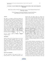
In order to underst<strong>and</strong> the difficulties associated with these<br />
steganalytic techniques, one such technique based on Row<br />
Gradient Profile of the image (Fig 8) is discussed in brief. It is a<br />
combination of pattern matching <strong>and</strong> statistical process <strong>and</strong> is<br />
a type of Neighborhood Analysis of the pixel.<br />
It analyzes the inter row difference of the intensity levels of<br />
the pixel in the image also known as Row Gradient Profile or<br />
Simply RG Profile of the image. The image used here is of<br />
60 x 130 pixels <strong>and</strong> 1080 characters are stored in it using algorithm<br />
developed in Section 4. Since each character is stored in<br />
1 pixel so first 18 rows of the image contain data. This interrow<br />
difference or Row Gradient of the image is plotted.<br />
As we can see that parameters of Cover-<strong>Image</strong> (Upper Graph)<br />
<strong>and</strong> Stego <strong>Image</strong> (Lower Graph) are clearly very different on<br />
the left of the black line (till 18 th Row of <strong>Image</strong>) <strong>and</strong> exactly<br />
identical on the right of the black line. But in real life scenario<br />
we will have only Stego <strong>Image</strong> from which we can obtain only<br />
lower graph. By using this lower graph only, it will be very<br />
difficult to conclusively say that image is a malicious stego<br />
image.<br />
6 CONCLUSION<br />
This paper provides a macro view of <strong>Steganography</strong> <strong>and</strong> Steganalysis<br />
<strong>and</strong> analyses the methods <strong>and</strong> reasons the terrorists<br />
are relying on it. Even a simple steganographic algorithm can<br />
hide data so efficiently that steganalysis become very difficult<br />
on various accords of time, computation power <strong>and</strong> money.<br />
But the real world terrorism uses more complex <strong>and</strong> innumerable<br />
steganographic algorithms. Till date we do not<br />
have any foolproof method of steganalysis. Considering the<br />
volume <strong>and</strong> size of information transferred over the web<br />
<strong>and</strong> the cost <strong>and</strong> time for steganalysis, it becomes virtually<br />
impossible to keep track of every file. Moreover most of the<br />
countries which are either centers of terrorism or its victims<br />
are second <strong>and</strong> third world countries (Fig 9) <strong>and</strong> do not<br />
have any dedicated <strong>and</strong> efficient system for policing such<br />
mammoth volumes of data flow. Interestingly some of<br />
these countries (mainly located in South East Asia <strong>and</strong><br />
IJSER © 2012<br />
http://www.ijser.org
<strong>International</strong> <strong>Journal</strong> of Scientific & Engineering Research Volume 3, Issue 7, July-2012 11<br />
ISSN 2229-5518<br />
Fig 8 Row Gradient Profile of 60 x 130 <strong>Image</strong> with 1080 Characters (First 18 Rows) stored using Algorithm developed in Section 4<br />
Middle East) have immense technical potential <strong>and</strong> vast<br />
Information Technology base but still most of them do not<br />
have any dedicated cyber security agency. Although Police<br />
Forces in most of the developing nations have started cyber<br />
cells for h<strong>and</strong>ling various cyber crimes <strong>and</strong> most of the<br />
strategic departments in emerging countries have established<br />
base, comm<strong>and</strong> <strong>and</strong> ministry level Information<br />
Technology Offices but their sole purpose is maintenance of<br />
information security in their own respective departments.<br />
None of them is dedicated for monitoring the internet traffic.This<br />
inherent weakness gives the Terrorist Leader the<br />
luxury to safely hide in countries where cyber-security is<br />
lackadaisical <strong>and</strong> inadequate.From such countries he keeps<br />
uploading malevolent images containing terrorist information<br />
<strong>and</strong> his Agents worldwide visit those concerned websites<br />
<strong>and</strong> keep getting his orders by just one click on the<br />
IJSER © 2012<br />
http://www.ijser.org<br />
Fig 9 Centers of <strong>Terrorism</strong> (as of 2009 from Wikipedia)<br />
image. On the one h<strong>and</strong> this technique hides the location of<br />
his agents <strong>and</strong> on the other h<strong>and</strong> it also provides the advantages<br />
of dead-dropping, anonymity <strong>and</strong> secure broadcasting<br />
worldwide. In this regard it is noteworthy to
<strong>International</strong> <strong>Journal</strong> of Scientific & Engineering Research Volume 3, Issue 7, July-2012 12<br />
ISSN 2229-5518<br />
mention that soon after establishment of US Cyber Comm<strong>and</strong><br />
(USCYBERCOM) the countries like China, Britain,<br />
North Korea <strong>and</strong> South Korea have already begun preparing<br />
their cyber force against international cyber space (including<br />
the ones of the terrorists as well as those of their<br />
enemies). But the situation is relatively grim in most other<br />
countries in general <strong>and</strong> developing countries in particular<br />
not just because of lack of technical knowhow, man power<br />
or money but also due to poor foresight. Hence the need of<br />
the hour is to take enduring <strong>and</strong> vigorous measures against<br />
Cyber <strong>Terrorism</strong> <strong>and</strong> at the same time experts from multiple<br />
disciplines <strong>and</strong> countries must join h<strong>and</strong>s to fight this<br />
menace to make world a safer place.<br />
NOTES AND REFERENCES<br />
[1]. Infosecurity Magazine article dated 02 May 2012 reports that Al-Qaeda uses<br />
<strong>Steganography</strong> to hide documents.<br />
http://www.infosecurity-magazine.com/view/25524/alqaeda-uses-steganographydocuments-hidden-in-porn-videos-found-on-memory-stick<br />
[2] Daily Mail Online, UK article dated 01 May 2012 reported that a Treasure<br />
trove of Intelligence was embedded in porn video.<br />
http://www.dailymail.co.uk/news/article-2137848/Porn-video-reveals-Al-Qaedaplanns-hijack-cruise-ships-execute-passengers.html#ixzz1uIgxpire<br />
[3].The New York Times article dated Oct 30, 2001 with title ―Veiled Messages of<br />
Terror May Lurk in Cyberspace‖ claims 9/11 attacks planned using <strong>Steganography</strong>.<br />
[4]Wired article dated 02 nd July, 2001 nicknamed Bin Laden as ―the <strong>Steganography</strong><br />
Master‖<br />
http://www.wired.com/politics/law/news/2001/02/41658?currentPage=all<br />
[5] In image processing the image matrix is represented as Columns by Row.<br />
Thus as per strict computer terminology this image will be called as 8 x 11 pixels<br />
image. But since this paper is meant for the readers of all backgrounds so we are<br />
following conventions of mathematics <strong>and</strong> hence we denote the image as Row by<br />
Column.<br />
[6] William Stallings- Cryptography <strong>and</strong> Network Security, Principles <strong>and</strong> Practices<br />
(5 th Edition, Section 2.5,Pg 53).<br />
[7] Jonathan Watkins, <strong>Steganography</strong> - Messages Hidden in Bits (15 th December,2001)<br />
http://mms.ecs.soton.ac.uk/mms2002/papers/6.pdf<br />
[8] krypt3ia article dated 13 th March 2010 with the title ―Al-Qaida goes ―Old<br />
School‖ With Tradecraft <strong>and</strong> <strong>Steganography</strong>‖ .<br />
http://krypt3ia.wordpress.com/2010/03/13/al-qaida-goes-old-school-withtradecraft-<strong>and</strong>-steganography/<br />
[9]Fabien A. P. Petitcolas,Information Hiding 5 th <strong>International</strong> WorkshopOct<br />
2002,Netherl<strong>and</strong>s (Pg 20, Volue V) mentions FBI Agent Robert Hanssen using<br />
steganography as electronic dead drop tool.<br />
http://books.google.co.in/books/about/Information_Hiding.html?id=jCKL2tSww<br />
VMC&redir_esc=y<br />
[10] Peter Wayner - Disappearing Cryptography: Information Hiding : <strong>Steganography</strong><br />
& Watermarking Second Edition (Pg 413) also mentions use of steganography<br />
as electronic dead drop tool.<br />
http://dl.acm.org/citation.cfm?id=560589<br />
[11] Ebay Online Auctions<br />
www.ebay.com<br />
[12] Johnson, Neil.F <strong>and</strong> Jajodia, Sushil. Steganalysis: The Investigation of Hidden<br />
Information, IEEE Information Technology Conference, Syracuse, New York,<br />
USA, September 1998<br />
http://akachuckie.com/text_files/SORTED/Hacking_<strong>and</strong>_Security_Guides/stega.p<br />
df<br />
[13] Niels Provos <strong>and</strong> Peter Honeyman, Center for Information Technology Integration<br />
University of Michigan, Detecting Steganographic Content on the Internet.<br />
The study of more than two million images downloaded from eBay auctions<br />
shows evidence that terrorists are using the images to hide encoded messages.<br />
http://www.citi.umich.edu/techreports/reports/citi-tr-01-11.pdf<br />
[14] SANS Institute InfoSec Reading Room<br />
http://www.sans.org/reading_room/<br />
[15] K B Shiva Kumar, K B Raja, Sabyasachi Pattnaik paper titled ―Hybrid Domain<br />
in LSB <strong>Steganography</strong>‖ <strong>International</strong> <strong>Journal</strong> of Computer Applications,<br />
Volume 19– No.7, April 2011<br />
[16] Lisa M. Marvel, Charles G. Boncelet, Jr. <strong>and</strong> Charles T. Retter, Spread Spectrum<br />
<strong>Image</strong> <strong>Steganography</strong>, IEEE Transactions on <strong>Image</strong> Processing, Vol. 8, No.<br />
8, August 1999<br />
http://www.fim.unilinz.ac.at/lva/Rechtliche_Aspekte/2001SS/Stegano/leseecke/spread%20spectrum%<br />
20image%20steganography.pdf<br />
[17] Stefan Katzenbeisser, Fabien A. P. Petitcolas, Information hiding techniques<br />
for steganography <strong>and</strong> digital watermarking chapter 3 Survey of Steganographic<br />
Techniques.<br />
http://www.jjtc.com/pub/book99_ih.htm<br />
[18] Pedram Hayati1, Vidyasagar Potdar2, <strong>and</strong> Elizabeth Chang A Survey of Steganographic<br />
<strong>and</strong> Steganalytic Tools for the Digital Forensic Investigator<br />
http://www.pedramhayati.com/images/docs/survey_of_steganography_<strong>and</strong>_stega<br />
nalytic_tools.pdf<br />
[19] R. Ch<strong>and</strong>ramouli, A Mathematical Approach to Steganalysis<br />
http://www.ece.stevens-tech.edu/~mouli/spiesteg02.pdf<br />
[20] A Web crawler is a computer program that browses the World Wide Web in a<br />
methodical, automated manner or in an orderly fashion. They are mainly used by<br />
serach engines for creating a copy of pages for later processing by a search engine<br />
that will index the pages to provide fast<br />
searches.http://en.wikipedia.org/wiki/Web_crawler.<br />
[21] Angela D. Orebaugh George Mason University, Steganalysis: A <strong>Steganography</strong><br />
Intrusion Detection System<br />
http://www.securityknox.com/Steg_project.pdf<br />
[22] J.R. Krenn, <strong>Steganography</strong> <strong>and</strong> Steganalysis January 2004<br />
http://www.krenn.nl/univ/cry/steg/article.pdf<br />
[23] Michael T Raggo, Identifying <strong>and</strong> Cracking <strong>Steganography</strong> Programs, Session<br />
65.<br />
http://www.spy-hunter.com/contact_information<br />
IJSER © 2012<br />
http://www.ijser.org