CEILINGVIEW⢠RECESSED CEILING INSTALLATION KIT - imaginArt
CEILINGVIEW⢠RECESSED CEILING INSTALLATION KIT - imaginArt
CEILINGVIEW⢠RECESSED CEILING INSTALLATION KIT - imaginArt

Create successful ePaper yourself
Turn your PDF publications into a flip-book with our unique Google optimized e-Paper software.
Camera and Electronic Products for Integrators<br />
Installation and User Guide<br />
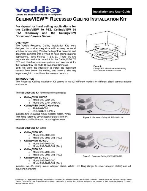
<strong>CEILING</strong>VIEW <strong>RECESSED</strong> <strong>CEILING</strong> <strong>INSTALLATION</strong> <strong>KIT</strong><br />
For drywall or hard ceiling applications for<br />
the CeilingVIEW 70 PTZ, CeilingVIEW 70<br />
PTZ HideAway and the CeilingVIEW<br />
Document Camera Series<br />
OVERVIEW<br />
The Vaddio Recessed Ceiling Installation Kits were<br />
designed to provide integrators with an easy to install<br />
solution for mounting Vaddio CeilingVIEW cameras and<br />
document cameras into drywall or hard ceiling material<br />
applications. (see Figures 1, 2 & 3). There are two<br />
separate kits available: one kit for the CeilingVIEW 70<br />
PTZ and HideAway camera systems and another kit for<br />
the CeilingVIEW SD and HD Document Cameras.<br />
Both kits allow the integrator to install the document<br />
camera from below the ceiling, and have a trim ring<br />
large enough to cover the entire camera back box.<br />
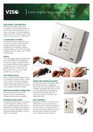
Figure 1:<br />
CeilingVIEW HD with recessed ceiling<br />
installation kit brackets attached<br />
INTRODUCTION<br />
The Recessed Ceiling Installation Kit comes in two (2) different models for different sized camera module<br />
enclosures.<br />
The 535-2000-210 Kit for the following models:<br />
• CeilingVIEW 70 PTZ<br />
o Model 999-2304-000<br />
o Model 999-2304-001(PAL)<br />
• CeilingVIEW 70 PTZ HideAway<br />
o 999-2404-000<br />
o 999-2404-001 (PAL)<br />
Includes two (2) ceiling mount adapter plates, White<br />
Trim Ring (larger to cover adapter plates) with IR<br />
extender board built-in and mounting hardware<br />
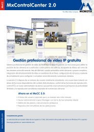
Figure 2: Recessed Ceiling Kit 535-2000-210<br />
The 535-2000-226 Kit is for:<br />
• CeilingVIEW HD<br />
o Model 999-3008-000<br />
o Model 999-3008-001 (PAL)<br />
• CeilingVIEW HD CCU<br />
o Model 999-3009-000<br />
o Model 999-3009-001 (PAL)<br />
• CeilingVIEW SD<br />
o Model 999-2008-000<br />
o Model 999-2008-001 (PAL)<br />
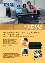
Figure 3: Recessed Ceiling Kit 535-2000-226<br />
• CeilingVIEW SD CCU<br />
o Model 999-2009-000<br />
o Model 999-2009-001 (PAL)<br />
Includes two (2) ceiling mount adapter plates, White Trim Ring (larger to cover adapter plates) and all<br />
mounting hardware<br />
©2008 Vaddio - All Rights Reserved. Reproduction in whole or in part without written permission is prohibited. Specifications and pricing subject to change.<br />
Vaddio, CeilingVIEW, and PowerRite are registered trademarks of Vaddio, Inc. All other trademarks are property of their respective owners. Document<br />
Number 341-264 Rev B.
INTENDED USE<br />
Before installing the Vaddio Recessed Ceiling Installation Kit or Vaddio CeilingVIEW Document Cameras,<br />
please read the entire manual thoroughly. All Vaddio camera systems were designed for use indoors.<br />
Outdoor operation is not recommended, hasn’t been tested, and could damage the camera and/or create a<br />
potentially unsafe operating condition. Use only the Vaddio PowerRite power supply provided.<br />
SAVE THESE INSTRUCTIONS<br />
The information contained in this manual will help you install the Vaddio Document Cameras in recessed<br />
ceiling applications. For reference, Vaddio keeps copies of Specifications, Installation and User Guides and<br />
most pertinent product drawings for the Vaddio product line on the website. These documents can be<br />
downloaded from www.vaddio.com free of charge.<br />
IMPORTANT SAFEGUARDS<br />
Read and understand all instructions before using. Do not operate the any electrical device if it has been<br />
dropped or damaged. In this case, a Vaddio technician must examine the product before operating. To<br />
reduce the risk of electric shock, do not immerse in water or other liquids and avoid extremely humid<br />
conditions.<br />
Use only the power supply provided with the Vaddio CeilingVIEW products. Use<br />
of any unauthorized power supply will void any and all warranties.<br />
INFORMATION<br />
Vaddio has prepared a number of TechNotes, specifications and drawings designed to inform and educate<br />
integrators on the value and the specific uses of Vaddio products.<br />
UNPACKING<br />
Carefully remove all of the parts from the packaging. Unpack and identify the following parts:<br />
Kit 535-2000-210<br />
• One (1) 14” (35.56) White trim ring with IR sensor board attached<br />
• Two (2) aluminum ceiling mount adapter plates<br />
• Mounting Hardware<br />
o Four (4) - #8 EZ Drywall Anchors with Four (4) - 2” #8 sheet metal screws<br />
o Four (4) – ¼”-20 x ½” Phillips pan head screws and lock washers<br />
o Two (2) – White trim ring screws<br />
• Installation and User Guide<br />
Kit 535-2000-226<br />
• One (1) 10-1/2” (26.67cm) White Trim Ring<br />
• Two (2) aluminum ceiling mount adapter plates<br />
• Mounting Hardware<br />
o Four (4) - #8 EZ Drywall Anchors with Four (4) - 2” #8 sheet metal screws<br />
o Four (4) – ¼”-20 x ½” Phillips pan head screws and lock washers<br />
o Two (2) – White trim ring screws<br />
• Installation and User Guide<br />
CeilingVIEW Recessed Ceiling Installation Kit 341-264 Rev. B Page 2 of 6
<strong>INSTALLATION</strong><br />
The CeilingVIEW products are integrated document/object cameras specifically designed for installation<br />
above a conference table, lectern or work surface. Recommended ceiling height range is between 8’ and 12’<br />
(2.44m to 3.66m). Make sure the measurements used for rough-openings, image orientation and location<br />
are 100% accurate prior to attempting installation (measure twice, cut once).<br />
Before Installing<br />
• Check above the ceiling tile or drywall where you plan to install the camera to make sure the area is<br />
clear and that there is adequate room for the CeilingVIEW Module and all of its components.<br />
• Pre-wire all cabling as required.<br />
• Please check the individual Vaddio CeilingVIEW Installation and User Guide manuals for special<br />
considerations pertaining to operability specific to the models used (i.e. the CeilingVIEW Document<br />
Cameras, used as part of a multi camera system, are required to be the last camera in the control chain<br />
to support the VISCA daisy chain control standard).<br />
Camera Module Cut-outs<br />
The following table contains the cutout dimensions for the recessed CeilingVIEW back box enclosures.<br />
TABLE 1:<br />
Vaddio Camera & Part Number<br />
Rough-opening<br />
Square Dimension<br />
Recessed<br />
Installation Kit<br />
CeilingVIEW 70 PTZ 9-1/4” (23.495cm) 535-2000-210<br />
CeilingVIEW 70 PTZ HideAway 9-1/4” (23.495cm) 535-2000-210<br />
CeilingVIEW SD & CCU 6” (15.24cm) 535-2000-226<br />
CeilingVIEW HD & CCU 6” (15.24cm) 535-2000-226<br />
MOUNTING INSTRUCTIONS<br />
The Recessed Ceiling Installation Kits can be installed in finished ceilings, as long as there are no<br />
obstructions above the drywall, or in new ceilings as long as the camera position, orientation and location<br />
over work surfaces is determined prior to installation.<br />
PRE-<strong>INSTALLATION</strong> INSTRUCTIONS<br />
Pre-wire all cable as required. Cabling after the ceiling is closed up can be challenging and time consuming.<br />
Step 1:<br />
Attach a string or plumb bob to the ceiling where the camera is to be located. Position the string directly over<br />
ample table space or work surface to allow easy document access and object positioning.<br />
Step 2:<br />
Draw the appropriate sized square (from Table 1) onto the drywall centered on the string. Cut out the<br />
marked square or in the case of a new construction have the drywall contractor cut the drywall to the proper<br />
dimension.<br />
Figure 4:<br />
Mark and cut the square in the<br />
drywall for the appropriate camera<br />
See Table 1<br />
CeilingVIEW Recessed Ceiling Installation Kit 341-264 Rev. B Page 3 of 6
Step 3:<br />
Attach the two (2) aluminum ceiling mount adapter plates with the four (4) – ¼”-20 x ½” Phillips pan head<br />
screws and lock washers.<br />
Figure 5:<br />
Aluminum ceiling mount adapter plate (right)<br />
and shown attached to (below)<br />
Step 4:<br />
Raise the module into the rough opening and mark the four (4) dry wall anchor locations.<br />
Figure 6:<br />
ISO View of CeilingVIEW<br />
module shown marking<br />
locations for drywall anchors<br />
Step 5:<br />
Using the supplied drywall anchors, insert the anchors into the drywall ceiling (Figure 7).<br />
Figure 7:<br />
Drywall anchors attached to<br />
drywall ceiling – pilot holes<br />
maybe required to avoid edge<br />
deterioration on drywall<br />
opening.<br />
Note: Other ceiling types may<br />
need other anchor types (i.e.<br />
toggle bolts) – not supplied.<br />
CeilingVIEW Recessed Ceiling Installation Kit 341-264 Rev. B Page 4 of 6
Step 6:<br />
Lift the camera module into place, connect the cables and push the camera firmly into the drywall, fasten the<br />
2” - #8 sheet metal screws through the flange of the ceiling mount adapter plate (Figure 8).<br />
Figure 8:<br />
Cable the camera and attach<br />
camera module to ceiling with the<br />
provided drywall anchor screws.<br />
Step 7: For Situations Requiring IR Pass-Thru<br />
For the CeilingVIEW SD and HD Document Cameras, attach the 10-1/2” diameter trim ring to the camera<br />
module with the supplied white screws. This installation should now be complete.<br />
For the CeilingVIEW 70 PTZ and the CeilingVIEW 70 PTZ HideAway, the IR sensor board is included on the<br />
14” diameter white trim ring. As always, take care not to pull any more than about 2 inches of cable out from<br />
the camera enclosure. The connectors will fit together only one way with a positive click. Carefully move trim<br />
ring into position on the bottom of camera while feeding IR cable back into camera enclosure and secure<br />
with the two supplied white screws. Installation for these models should now be complete.<br />
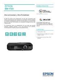
Figure 9:<br />
Left: Small trim ring (10-1/2”)<br />
for CeilingVIEW Visualizer<br />
Right: Larger trim ring (14”)<br />
for CeilingVIEW 70 PTZ and<br />
CeilingVIEW 70 PTZ<br />
HideAway with IR sensor<br />
board mounted to trim ring<br />
IR Sensor Board<br />
14” Trim Ring Only<br />
4-3/4”<br />
5-7/16”<br />
10-1/2”<br />
14”<br />
Step 8:<br />
See all other individual product installation and user guides for initial power-up and all other functionality and<br />
set-up of the Vaddio CeilingVIEW cameras.<br />
CeilingVIEW Recessed Ceiling Installation Kit 341-264 Rev. B Page 5 of 6
CARE AND CLEANING<br />
• Do not attempt to take the products in these systems apart. There are no user-serviceable components.<br />
• Keep these devices away from food and liquid, and do not spill liquids on the products<br />
• For smears or smudges on the lens, wipe with a clean, soft cloth - see Polycom user guide for details.<br />
Do not use any abrasive chemicals on the camera body at any time.<br />
OPERATING AND STORAGE CONDITIONS<br />
Do not store or operate the CeilingVIEW products under the following conditions:<br />
• Temperatures above 40°C (104°F) or below 0°C (32°F), for Indoor Use Only<br />
• High humidity, condensing or wet environments<br />
• Dusty environments<br />
• In inclement weather<br />
• Under severe vibration<br />
WARRANTY INFORMATION<br />
Hardware* Warranty - One year limited warranty on all parts. Vaddio warrants this product against defects in materials and<br />
workmanship for a period of one year from the day of purchase from Vaddio. If Vaddio receives notice of such defects during the<br />
warranty period, they will, at their option, repair or replace products that prove to be defective.<br />
Exclusions - The above warranty shall not apply to defects resulting from: improper or inadequate maintenance by the customer,<br />
customer applied software or interfacing, unauthorized modifications or misuse, operation outside the normal environmental<br />
specifications for the product, use of the incorrect power supply, improper extension of the power supply cable or improper site<br />
operation and maintenance.<br />
Vaddio Customer service – Vaddio will test, repair, or replace the product or products without charge if the unit is under warranty and<br />
is found to be defective. If the product is out of warranty, Vaddio will test then repair the product or products. The cost of parts and labor<br />
charge will be estimated by a technician and confirmed by the customer prior to repair. All components must be returned for testing as a<br />
complete unit. Vaddio will not accept responsibility for shipment after it has left the premises.<br />
Vaddio Technical support - Vaddio technicians will determine and discuss with the customer the criteria for repair costs and/or<br />
replacement. Vaddio Technical Support can be contacted through one of the following resources: e-mail support at<br />
support@vaddio.com or online at www.vaddio.com.<br />
Return Material Authorization (RMA) number - Before returning a product for repair or replacement, request an RMA from Vaddio’s<br />
technical support. Provide a technician with a return phone number, e-mail address, shipping address, and product serial numbers and<br />
describe the reason for repairs or returns as well as the date of purchase and proof of purchase. Include your assigned RMA number in<br />
all correspondence with Vaddio. Write your assigned RMA number on the shipping label of the box when returning the product. Please<br />
see Vaddio’s website for current RMA policies and procedures.<br />
Voided warranty – The warranty does not apply if the original serial number has been removed or if the product has been<br />
disassembled or damaged through misuse, accident, modifications, or unauthorized repair. Cutting the power supply cable on the<br />
secondary side (low voltage side) to extend the power to the device (camera or controller) voids the warranty for that device.<br />
Shipping and handling - Vaddio will not pay for inbound shipping transportation or insurance charges or accept any responsibility for<br />
laws and ordinances from inbound transit. Vaddio will pay for outbound shipping, transportation, and insurance charges for all items<br />
under warranty but will not assume responsibility for loss and/or damage by the outbound freight carrier. If the return shipment appears<br />
damaged, retain the original boxes and packing material for inspection by the carrier. Contact your carrier immediately.<br />
Products not under warranty - Payment arrangements are required before outbound shipment for all out of warranty products.<br />
*Vaddio manufactures its hardware products from parts and components that are new or equivalent to new in accordance with industry<br />
standard practices.<br />
9433 Science Center Drive, Minneapolis, MN 55428<br />
Toll Free: 800-572-2011 ▪ Phone: 763-971-4400 ▪ FAX: 763-971-4464<br />
www.vaddio.com<br />
©2008 Vaddio - All Rights Reserved. Reproduction in whole or in part without written permission is prohibited. Specifications and pricing<br />
subject to change. Vaddio, CeilingVIEW, and PowerRite are registered trademarks of Vaddio. All other trademarks are property of their<br />
respective CeilingVIEW owners. Recessed Document Ceiling Number Installation 341-264 Kit 341-264 Rev B. Rev. B Page 6 of 6