BEI Model H25X Absolute Optical Encoder - Ä°maj Teknik
BEI Model H25X Absolute Optical Encoder - Ä°maj Teknik
BEI Model H25X Absolute Optical Encoder - Ä°maj Teknik

You also want an ePaper? Increase the reach of your titles
YUMPU automatically turns print PDFs into web optimized ePapers that Google loves.
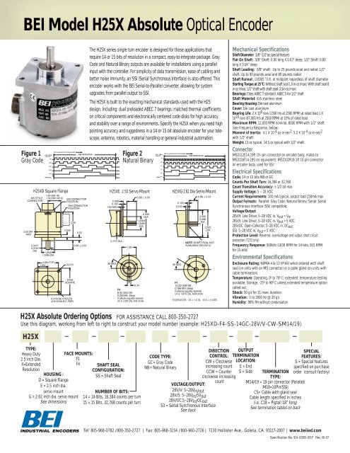
<strong>BEI</strong> <strong>Model</strong> <strong>H25X</strong> <strong>Absolute</strong> <strong>Optical</strong> <strong>Encoder</strong><br />
Figure 1<br />
Gray Code<br />
MS STYLE<br />
CONNECTOR<br />
2.52 DIA<br />
MAX<br />
ETC. THRU<br />
LSB (GO)<br />
G9<br />
G10<br />
G11<br />
G12<br />
G13<br />
MSB (G14)<br />
CW Increasing Count Viewing Shaft<br />
<strong>H25X</strong>D Square Flange<br />
0.3747<br />
0.3745<br />
DIA<br />
1.65 (SM 18)<br />
1.30 (SM 14/19)<br />
1.2500<br />
1.2495 DIA<br />
ONE REVOLUTION<br />
EM CONNECTOR<br />
POSITION<br />
SM CONNECTOR<br />
POSITION<br />
0.255<br />
2.50<br />
2.064 TYP<br />
1.032 0.21 R<br />
2.650<br />
SQUARE<br />
0.218 DIA 4 HOLES<br />
(2.919 DIA B.C. REF)<br />
0.30<br />
0.88 ± 0.03<br />
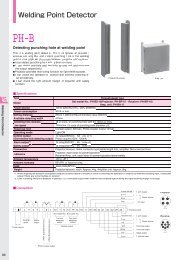
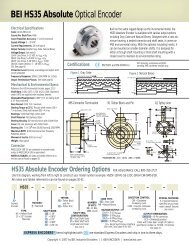
The <strong>H25X</strong> series single turn encoder is designed for those applications that<br />
require 14 or 15 bits of resolution in a compact, easy-to-integrate package. Gray<br />
Code and Natural Binary outputs are available for installations using a parallel<br />
input with the controller. For simplicity of data transmission, ease of cabling and<br />
better noise immunity, an SSI (Serial Synchronous Interface) is also offered. This<br />
encoder works with the <strong>BEI</strong> Serial-to-Parallel converter, allowing for system<br />
upgrades from parallel output to SSI.<br />
The <strong>H25X</strong> is built to the exacting mechanical standards used with the H25<br />
design, including: dual preloaded ABEC 7 bearings; matched thermal coefficients<br />
on critical components and electronically centered code disks for high accuracy<br />
and stability over a range of environments. Specify the <strong>H25X</strong> when you need high<br />
pointing accuracy and ruggedness in a 14 or 15 bit absolute encoder for your telescope,<br />
antenna, robotics, material handling or general industrial automation.<br />
0.300<br />
0.100<br />
.100 MIN<br />
2.275 DIA<br />
Figure 2<br />
Natural Binary<br />
<strong>H25X</strong>E 2.50 Servo Mount<br />
1.38<br />
2.500<br />
DIA<br />
1.2500<br />
1.2495<br />
DIA<br />
0.34<br />
F4<br />
6-32 UNC-2B<br />
0.250 Min. Deep<br />
3 places equally spaced<br />
on a 2.00 Dia. bolt circle.<br />
ETC. THRU<br />
LSB (2 0 )<br />
2 9<br />
2 10<br />
2 11<br />
2 12<br />
2 13<br />
MSB (2 14 )<br />
CW Increasing Count Viewing Shaft<br />
0.125<br />
0.125<br />
ONE REVOLUTION<br />
<strong>H25X</strong>G 2.62 Dia Servo Mount<br />
2.500<br />
2.498<br />
DIA<br />
2.625<br />
DIA<br />
NOTE: SHAFT SEAL NOT<br />
AVAILABLE ON H25 G<br />
F1<br />
10-32 UNF-2B<br />
0.188 Min. Deep<br />
3 places equally spaced<br />
on a 1.875 Dia. bolt circle.<br />
TOLERANCES: .XX = ±0.01, .XXX = ±0.005<br />
Mechanical Specifications<br />
Shaft Diameter: 3/8" (1/2"as special feature)<br />
Flat On Shaft: 3/8" Shaft: 0.80 long X 0.03" deep; 1/2" Shaft: 0.80<br />
long X 0.04” deep<br />
Shaft Loading: 3/8" shaft: Up to 25 pounds axial and radial; 1/2"<br />
shaft: Up to 90 pounds axial and 80 pounds radial<br />
Shaft Runout: 0.0005 T.I.R. at midpoint regardless of shaft diameter<br />
Starting Torque at 25°C: Without shaft seal 1.0 in-oz (max); With shaft seal 8<br />
in-oz (max); 1/2" shaft with shaft seal: 3.5in-oz (max)<br />
Bearings: Class ABEC 7 standard, ABEC 5 for 1/2" shaft<br />
Shaft Material: 416 stainless steel<br />
Bearing Housing: Die cast aluminum<br />
Cover: Die cast aluminum<br />
Bearing Life: 2 X 10 8 revs (1300 hrs at 2500 RPM) at rated load 1 X<br />
10 10 revs (67,000 hrs at 2500 RPM) at 10% of rated load<br />
Maximum RPM: 12,000 RPM nominal, 8000 RPM with 1/2" shaft<br />
(see Frequency Response, below)<br />
Moment of Inertia: 4.1 X 10 -4 oz-in-sec 2 ; 5.2 X 10 -4 oz-in-sec 2<br />
with 1/2" shaft<br />
Weight: 13 oz typical, 14.5 oz typical with 1/2" shaft<br />
Connector<br />
MS3112E14-19P, 19–pin connector on encoder body, mates to<br />
MS3116F14-19S (or equivalent); MS3102R18-1P, 10-pin connector<br />
on encoder body, used for SSI<br />
Electrical Specifications<br />
Code: 14 or 15 bits NB or GC<br />
Counts Per Shaft Turn: 16,384 or 32,768<br />
Count Transition Accuracy: ± 1/2 bit max<br />
Supply Voltage: 5 – 28 VDC<br />
Current Requirements: 100 mA typical, output load 250mA max<br />
Output Formats: Parallel: Gray Code, Natural Binary; Serial: Serial<br />
Synchronous Interface (SSI) compatible;<br />
Voltage/Output:<br />
28V/V: Line Driver, 5–28 VDC in, Vout = Vin<br />
28V/5: Line Driver, 5–28 VDC in, Vout = 5 VDC<br />
28V/OC: Open Collector, 5–28 VDC in, OCout<br />
SSI: 5–28 VDC in, Vout = 5 VDC<br />
Protection Level: Reverse, overvoltage and output short circuit<br />
protection (7272 only)<br />
Frequency Response: 500kHz (1830 RPM for 14-bits, 915 RPM<br />
for 15-bits)<br />
Environmental Specifications<br />
Enclosure Rating: NEMA 4 & 13 (IP 66) when ordered with shaft<br />
seal (on units with an MS connector) or a cable gland (on units with<br />
cable termination).<br />
Temperature: Operating, 0º to 70º C; extended temperature testing<br />
available; Storage, -25º to 90º C unless extended temperature option<br />
called out.<br />
Shock: 50 g’s for 11 msec duration<br />
Vibration: 5 to 2000 Hz @ 20 g’s<br />
Humidity: 98% RH without condensation<br />
<strong>H25X</strong> <strong>Absolute</strong> Ordering Options FOR ASSISTANCE CALL 800-350-2727<br />
Use this diagram, working from left to right to construct your model number (example: <strong>H25X</strong>D-F4-SS-14GC-28V/V-CW-SM14/19).<br />
<strong>H25X</strong><br />
TYPE:<br />
Heavy Duty<br />
2.5 inch Dia.<br />
X=Extended<br />
Resolution<br />
FACE MOUNTS:<br />
F1<br />
F4<br />
HOUSING :<br />
D = Square Flange<br />
E = 2.5 inch dia.<br />
servo mount<br />
G = 2.62 inch dia. servo mount<br />
See dimensions<br />
SHAFT SEAL<br />
CONFIGURATION:<br />
SS = Shaft Seal<br />
NUMBER OF BITS:<br />
14 = 14-Bits, 16,384 counts per turn<br />
15 = 15 Bits, 32,768 counts per turn<br />
CODE TYPE:<br />
GC = Gray Code<br />
NB = Natural Binary<br />
VOLTAGE/OUTPUT:<br />
28V/V: 5–28Vin/out<br />
28V/5: 5–28Vin/5Vout<br />
28V/OC:5–28Vin/OCout<br />
S3 = Serial Synchronous Interface<br />
See back<br />
DIRECTION<br />
CONTROL:<br />
CW = Clockwise<br />
increasing count<br />
CCW = Counter<br />
clockwise increasing<br />
count<br />
OUTPUT<br />
TERMINATION<br />
LOCATION:<br />
E = End<br />
S = Side<br />
TERMINATION<br />
TYPE:<br />
M14/19 = 19 pin connector (Parallel)<br />
M18=10Pin(SSI)<br />
CS= Cable with gland seal<br />
Cable length specified in inches<br />
(i.e. C18 = Pigtail 18” long)<br />
See termination tables on back<br />
SPECIAL<br />
FEATURES:<br />
S = Special features<br />
specified on purchase<br />
order (consult factory)<br />
Tel: 805-968-0782 /800-350-2727 | Fax: 805-968-3154 / 800-960-2726 | 7230 Hollister Ave., Goleta, CA 93117-2807 | www.beiied.com<br />
Specification No. 924-02085-001F Rev. 06-07
Serial Synchronous Interface (SSI)<br />
SSI output provides effective synchronization in a closed-loop control system.<br />
A clock pulse train from a controller is used to clock out sensor data: one bit of position<br />
data is transmitted to the controller per one clock pulse received by the sensor.<br />
The use of a differential driver permits reliable transmission of data over long distances<br />
in environments that may be electrically noisy. The encoder utilizes a clock<br />
signal, provided by the user interface, to time the data transmission. Receiving electronics<br />
must include an appropriate receiver as well as line terminating resistors.<br />
Features<br />
• Synchronous transmission<br />
• Transmission lengths to 1000 feet<br />
• Accepts clock rates from 100 KHz to 1.8 MHz<br />
Data Transmission Sequence<br />
1. Output driver of the encoder is a MAX 491 transceiver in transmit mode.<br />
It is recommended to use any RS–422/485 compatible receiver and provide a termination<br />
resistor based on the RS–422/485 specification for your specific voltage and<br />
DATA line strength.<br />
2. The CLOCK signals are RS–422/485 compatible, differential TTL, with 180 Ohm termination<br />
resistor internal to the encoder. A series of pulses from the controller, on<br />
the CLOCK lines, advance the data.<br />
3. On the first HIGH-to-LOW CLOCK transition, the encoder latches its data at the<br />
current position and prepares to transmit. The DATA signal during this transition is a<br />
START bit, which is always HIGH.<br />
4. The encoder shifts data to the data line on each LOW-to-HIGH transition beginning<br />
with the MSB. The controller reads data on the HIGH-to-LOW transition of the next<br />
16 CLOCK CYCLES ending with parity (optional and = logic ‘lo’ if not specified). Bit<br />
15, if specified, is provided on the 15th CLOCK CYCLE and = logic ‘lo’ if 14 Bit<br />
encoder is specified.<br />
5. Parity is even. The sum of all data bits and the parity bit is even.<br />
6. After the last CLOCK High-to-LOW transition, a minimum of 40 microseconds must<br />
pass before the beginning of the next CLOCK series.<br />
Interfacing Long Data Lines<br />
Cable impedance can create a transmission delay, in effect, shifting the phase relationship<br />
between the clock pulse and the data. If this phase shift exceeds 180°, then<br />
the wrong bit position will be sampled by the receiver. As a result, the maximum<br />
allowable clock frequency is a function of the cable length. For 24 AWG, stranded, 3<br />
pair cable (<strong>BEI</strong> part number 37048-003 or equivalent) the group delay is 1.36ns/ft. The<br />
table below shows the maximum transmission rate allowable as a function of cable<br />
length to ensure a phase shift of less than 90°.<br />
CLOCK, Maximum (kHz) = 92,000 / Cable Length (ft)CW<br />
Cable Length (ft) 50 100 200 300 500 1000<br />
Max Freq (kHz) 1800 900 500 300 200 100<br />
Parallel Code (14 & 15 Bit)<br />
M14/19<br />
Gray Code Natural Binary Connector<br />
14 BIT 15 Bit 14 BIT 15 Bit<br />
MSB G 13 G 14 2 13 2 14 A<br />
G 12 G 13 2 12 2 13 B<br />
G 11 G 12 2 11 2 12 C<br />
G 10 G 11 2 10 2 11 D<br />
G 9 G 10 2 9 2 10 E<br />
G 8 G 9 2 8 2 9 F<br />
G 7 G 8 2 7 2 8 G<br />
G 6 G 7 2 6 2 7 H<br />
G 5 G 6 2 5 2 6 J<br />
G 4 G 5 2 4 2 5 K<br />
G 3 G 4 2 3 2 4 L<br />
G 2 G 3 2 2 2 3 M<br />
G 1 G 2 2 1 2 2 N<br />
LSB14 G 0 G 1 2 0 2 1 P<br />
LSB15 DIR G 0 DIR 2 0 R<br />
CONTROL<br />
CONTROL<br />
CASE GROUND<br />
S<br />
OV (CIRCUIT COMMON)<br />
T<br />
LATCH DIR/LATCH LATCH DIR/LATCH U<br />
+V (SUPPLY +V (SUPPLY +V (SUPPLY +V (SUPPLY V<br />
VOLTAGE) VOLTAGE) VOLTAGE) VOLTAGE)<br />
Direction Control: Standard is CW increasing when viewed from the shaft end. Direction<br />
Control is normally HI (or N/C) and is pulled up with a 10K ohm resistor internally to +V. To<br />
reverse the count direction, Direction Control must be pulled LO (COMMON ).<br />
Latch control: <strong>Encoder</strong> outputs are active and provide continuous parallel position information<br />
when latch is HI (or N/C). Latch is pulled up with a 10K ohm resistor internally to +V.<br />
When latch is LO (COMMON) the encoder outputs are held at the logic state present when<br />
the latch is applied and stays held until latch is no longer grounded.<br />
Enable: Output is active when this pin is HI. When pulled LO (Circuit Common) all outputs<br />
go to high impedance state (Tri-state) and are inactive until LO state is removed. This pin is<br />
pulled HI with a 10K ohm resistor internally to +V.<br />
15-Bit <strong>Encoder</strong>s: Due to a limited number of connector pins, either direction control, latch<br />
or enable are available on Pin U. Direction control is standard. Latch or enable can be ordered<br />
as a special feature and will replace direction control on Pin U.<br />
M18 Connector is a MS3102R18-1P, 10-pin connector on the encoder body and mates to an<br />
MS3106F18-1S connector or can be used with a standard cable/connector assembly, <strong>BEI</strong> P/N<br />
924-31186-18XX (Where X = 10, 20 or 30 for a 10, 20, or 30 foot length). This is the preferred<br />
connector for SSI output.<br />
M14/19 Connector is a MS3112E14-19P, 19-pin connector on the encoder body and mates<br />
to an MS3116F14-19S or equivalent. Or cable ASSY 31219–14x (XX = cable length in feet,<br />
i.e., 10, 20, 30 = 10, 20, 30 feet respectively)<br />
SSI Compatible Serial Code (S3):<br />
Connector Term Board<br />
Function Cable M18 M14/19 H40 H38<br />
DATA+ YEL A A 1 4<br />
DATA- WHT/YEL H B 7 7<br />
CLOCK+ BLU B C 2 5<br />
CLOCK- WHT/BLU I D 8 8<br />
DIRECTION CONTROL ORN C R 3 6<br />
ENABLE (OPTIONAL) WHT/ORN J P 9 9<br />
SUPPLY VOLTAGE (+V) RED D V 4 3<br />
CIRCUIT COMMON (OV) BLK F T 5 2<br />
CASE GROUND GRN G S 6 1<br />
SHIELD DRAIN BARE – – – –<br />
Tel: 805-968-0782 /800-350-2727 | Fax: 805-968-3154 / 800-960-2726 | 7230 Hollister Ave., Goleta, CA 93117-2807 | www.beiied.com