Aerodynamic Design of Unmanned and Scaled Supersonic ...
Aerodynamic Design of Unmanned and Scaled Supersonic ...
Aerodynamic Design of Unmanned and Scaled Supersonic ...

You also want an ePaper? Increase the reach of your titles
YUMPU automatically turns print PDFs into web optimized ePapers that Google loves.
K. Yoshida <strong>and</strong> Y. Makino<br />
configuration was called “0-1st Configuration” <strong>of</strong><br />
the NEXST-2 airplane.<br />
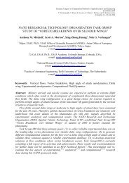
Figure 14 shows a wind tunnel test model for<br />
the “0-1st Configuration”. It had a flow-plug just<br />
after two nacelles <strong>and</strong> several total pressure<br />
measurement tubes placed near exit station <strong>of</strong> the<br />
nacelle. We were able to control the inflow<br />
entering into the intake by changing the plug<br />
position. We obtained useful experimental data<br />
using this model, as mentioned later.<br />
In the conceptual design phase, the “0-1st<br />
Configuration” was the start point. As the next<br />
step, we designed from the “0-2nd Configuration” to “0-8th Configuration” considering an<br />
area-ruled body concept based on linear theory, some improvements <strong>of</strong> nacelle configuration<br />
<strong>and</strong> its position, optimization <strong>of</strong> intake geometry, <strong>and</strong> aerodynamic tail-volume. This design<br />
process was not straight-forward but a process <strong>of</strong> trial <strong>and</strong> error approach in reducing<br />
aerodynamic drag within several constraints required in practice.<br />
2) <strong>Aerodynamic</strong> optimum design phase<br />
(a) Baseline configuration design<br />
The “0-8th Configuration” was only designed from the aerodynamic viewpoint. To<br />
develop a practical experimental airplane, it was necessary to compromise the following<br />
fields: airframe aerodynamics, structural constraints, flight dynamics, intake aerodynamics,<br />
<strong>and</strong> propulsion system performance. As the first step, we designed the “1st Configuration”<br />
using present CFD-based aerodynamic design method, maintaining several practical design<br />
constraints required by industries.<br />
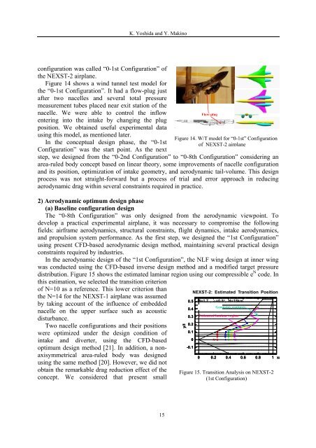
In the aerodynamic design <strong>of</strong> the “1st Configuration”, the NLF wing design at inner wing<br />
was conducted using the CFD-based inverse design method <strong>and</strong> a modified target pressure<br />
distribution. Figure 15 shows the estimated laminar region using our compressible e N code. In<br />
this estimation, we selected the transition criterion<br />
<strong>of</strong> N=10 as a reference. This lower criterion than<br />
the N=14 for the NEXST-1 airplane was assumed<br />
by taking account <strong>of</strong> the influence <strong>of</strong> embedded<br />
nacelle on the upper surface such as acoustic<br />
disturbance.<br />
Two nacelle configurations <strong>and</strong> their positions<br />
were optimized under the design condition <strong>of</strong><br />
intake <strong>and</strong> diverter, using the CFD-based<br />
optimum design method [21]. In addition, a nonaxisymmetrical<br />
area-ruled body was designed<br />
using the same method [20]. However, we did not<br />
obtain the remarkable drag reduction effect <strong>of</strong> the<br />
concept. We considered that present small<br />
Flow-plug<br />
Figure 14. W/T model for “0-1st” Configuration<br />
<strong>of</strong> NEXST-2 airplane<br />
y/l<br />
0.5<br />
0.4<br />
0.3<br />
0.2<br />
0.1<br />
0<br />
-0.1<br />
NEXST-2: Estimated Transition Position<br />
M=1.7 , α=0.5°, H=15km<br />
Wb0803aGeometry contours<br />
Estimated laminar region<br />
N=2 4 6 8 10<br />
0 0.2 0.4 0.6 0.8 1 x/<br />
Figure 15. Transition Analysis on NEXST-2<br />
(1st Configuration)<br />
15