new way of accuracy improvement for the pneumatic ... - imeko
new way of accuracy improvement for the pneumatic ... - imeko
new way of accuracy improvement for the pneumatic ... - imeko

You also want an ePaper? Increase the reach of your titles
YUMPU automatically turns print PDFs into web optimized ePapers that Google loves.
Proceedings, XVII IMEKO World Congress, June 22 – 27, 2003, Dubrovnik, Croatia<br />
Proceedings, XVII IMEKO World Congress, June 22 – 27, 2003, Dubrovnik, Croatia<br />
TC1<br />
TC16<br />
XVII IMEKO World Congress<br />
Metrology in <strong>the</strong> 3 rd Millennium<br />
June 22−27, 2003, Dubrovnik, Croatia<br />
NEW WAY OF ACCURACY IMPROVEMENT FOR THE PNEUMATIC<br />
DEADWEIGHT TESTER V1600<br />
M. Bryant 1 , N. Moisoi 1 and S.M.Kesselman 2<br />
1 Pressurements Limited, Dunstable, UK<br />
2 Pressure laboratory, Russian Research Institute <strong>for</strong> Metrological Service (VNIIMS), Moscow, Russia<br />
Abstract - The V1600 is a compact portable pressure<br />
balance suitable <strong>for</strong> applications where a large number <strong>of</strong><br />
high <strong>accuracy</strong> calibrations in ranges from 20 Pa up to 16<br />
kPa, need to be per<strong>for</strong>med on a daily basis.<br />
Calibrations per<strong>for</strong>med at VNIIMS, LNE, MIKE,<br />
NIST and PTB have shown <strong>the</strong> uncertainty <strong>of</strong> <strong>the</strong> V1600 is<br />
less than 0.1 Pa below 500 Pa and 0.02% <strong>of</strong> reading from<br />
500 Pa to 16 kPa.<br />
An important part <strong>of</strong> <strong>the</strong> uncertainty <strong>of</strong> <strong>the</strong> instrument<br />
within <strong>the</strong> range 500 Pa to 16 kPa has been caused by a<br />
methodical error <strong>of</strong> <strong>the</strong> procedure applied to its calibration<br />
until now.<br />
This paper presents <strong>the</strong> original manner <strong>of</strong> detection<br />
and elimination <strong>of</strong> <strong>the</strong> above-mentioned systematic error.<br />
This <strong>new</strong> calibration approach is based on <strong>the</strong> equality<br />
<strong>of</strong> Eulerian criterion <strong>of</strong> <strong>the</strong> actual device with its<br />
ma<strong>the</strong>matical model and allows an increase <strong>of</strong> <strong>the</strong><br />
calibration <strong>accuracy</strong> with approximately 1,5 – 2 times <strong>for</strong><br />
pressures above 500 Pa.<br />
Key words: deadweight tester, <strong>accuracy</strong>, calibration.<br />
Introduction<br />
A full description <strong>of</strong> V1600 is given in [1]. The main<br />
instrument component is a transducer, which trans<strong>for</strong>ms <strong>the</strong><br />
gravitational <strong>for</strong>ce Mg <strong>of</strong> <strong>the</strong> piston and loads into a<br />
<strong>pneumatic</strong> pressure P using a system consisting in a variable<br />
throttle (piston-nozzle assembly) and a fixed throttle (<strong>the</strong><br />
gap between nozzle and nozzle-body).<br />
The output pressure <strong>of</strong> <strong>the</strong> transducer is applied to <strong>the</strong><br />
inlet <strong>of</strong> a two-cascade regulator, which has <strong>the</strong> role to<br />
support <strong>the</strong> piston with high <strong>accuracy</strong> at a particular height<br />
above <strong>the</strong> edge <strong>of</strong> nozzle.<br />
As <strong>the</strong> air flows through <strong>the</strong> gap between <strong>the</strong> piston<br />
cone and <strong>the</strong> nozzle, a reactive feedback <strong>for</strong>ce R is<br />
generated.<br />
There<strong>for</strong>e <strong>the</strong> measurement equation <strong>of</strong> V1600<br />
pressure balance can be written as follows:<br />
P = Mg (1 - ρ a /ρ m )/A 0 + R/ A 0, (1)<br />
where: (1 - ρ a /ρ m ) – air buoyancy correction factor,<br />
R = G (υCosβ - υ 1 )/ A 0 ,<br />
A 0 - geometrical area <strong>of</strong> <strong>the</strong> nozzle’s edge,<br />
G - mass flow rate,<br />
υ and - υ 1 velocity <strong>of</strong> <strong>the</strong> gas exhausting from <strong>the</strong><br />
nozzle-piston gap and respective velocity <strong>of</strong> <strong>the</strong> gas<br />
in <strong>the</strong> space under <strong>the</strong> piston,<br />
h – effective gap between <strong>the</strong> piston and nozzle in a<br />
perpendicular direction <strong>of</strong> <strong>the</strong> velocity υ,<br />
2β - angle at <strong>the</strong> peak <strong>of</strong> <strong>the</strong> piston cone.<br />
The most convenient <strong>way</strong> to use <strong>the</strong> V1600 pressure<br />
balance is to know its main parameter, <strong>the</strong> effective area:<br />
A = A 0 (1 - q), (2)<br />
where: q = G (υCosβ - υ 1 ) /Mg which can be re-written:<br />
q = (4hCosβ)/(R 0 Eu), as υ 1
Proceedings, XVII IMEKO World Congress, June 22 – 27, 2003, Dubrovnik, Croatia<br />
Proceedings, XVII IMEKO World Congress, June 22 – 27, 2003, Dubrovnik, Croatia<br />
TC1<br />
TC16<br />
The effective area <strong>of</strong> V1600 can be determined by<br />
direct comparison with a pressure standard <strong>of</strong> a higher<br />
<strong>accuracy</strong>.<br />
The problem arises when it is necessary to calibrate or<br />
to test pressure instruments with an uncertainty less than<br />
(0,05 – 0,1) Pa in <strong>the</strong> range below 3000 Pa, where very <strong>of</strong>ten<br />
it is not possible to determine <strong>the</strong> effective area by direct<br />
comparison.<br />
There<strong>for</strong>e <strong>the</strong> effective area <strong>of</strong> each V1600 is<br />
determined accordingly with <strong>the</strong> original method <strong>of</strong><br />
calibration described in [2]. This method is based on<br />
definition <strong>of</strong> effective area A c , at a pressure P c ,<br />
corresponding to <strong>the</strong> mass M c (including piston, carrier and<br />
weights), within its range, which is accessible to <strong>the</strong><br />
available standard, <strong>for</strong> example: 3, 6 or 16 kPa.<br />
The equation <strong>of</strong> calibration is given by:<br />
The main component <strong>of</strong> V1600 is a divider <strong>of</strong> <strong>the</strong><br />
supply pressure P s acting on its inlet. The dependence<br />
between <strong>the</strong>oretical output pressure P <strong>of</strong> <strong>the</strong> divider and<br />
pressure P s on its inlet can be given by:<br />
P s = θ P, (5)<br />
where: θ -<strong>the</strong> relationship <strong>of</strong> throttles conductivity.<br />
The value <strong>of</strong> coefficient θ depends on <strong>the</strong> modes <strong>of</strong> <strong>the</strong><br />
gas flow through <strong>the</strong> throttles and can be determined from<br />
equality <strong>of</strong> <strong>the</strong> flow rate through <strong>the</strong> throttles.<br />
The fixed throttle <strong>of</strong> <strong>the</strong> divider is manufactured as an<br />
annual gap between <strong>the</strong> nozzle and <strong>the</strong> nozzle-body with <strong>the</strong><br />
nominal value <strong>of</strong> <strong>the</strong> width H = (0,15 – 0,17) mm and <strong>the</strong><br />
length L =10 mm, Fig. 1.<br />
A j = A c [1 – q c (q c /q j – 1)] (4)<br />
where: q c = G c υ c Cosβ/M c g,<br />
υ c = {[2kRT/(k-1)]*[1 – (p a /p) (k-1)/k ]} 1/2 or<br />
υ c =(2P/ρ) 1/2 as in <strong>the</strong> range from 0,02 up to 16 kPa<br />
<strong>the</strong> compressibility <strong>of</strong> <strong>the</strong> air can be neglected,<br />
q j /q c = {(p j /p c ) 1/k [(P sj - P j )/(P sc - P c )]*(M c M j )} 1/2<br />
p j and p c – absolute pressure corresponding to <strong>the</strong><br />
pressure P c ∼M c g/A 0 and P j ∼ M j g/ A 0 , P sj , as long as<br />
<strong>the</strong> real value <strong>of</strong> A 0 is unknown,<br />
R - universal gas constant,<br />
T - absolute temperature,<br />
k – adiabatic index.<br />
The analysis <strong>of</strong> <strong>the</strong> calibration results from several<br />
instruments has shown that <strong>the</strong> relative <strong>accuracy</strong>, due to<br />
calibration method, begins to increase at 700 Pa and reaches<br />
up to 0,009 % at 16 kPa.<br />
The purpose <strong>of</strong> this paper is to present <strong>the</strong> original<br />
manner <strong>of</strong> detection and elimination <strong>of</strong> above mentioned<br />
systematic error.<br />
New <strong>way</strong> <strong>of</strong> <strong>accuracy</strong> <strong>improvement</strong> <strong>for</strong> <strong>the</strong> V1600<br />
This behavior <strong>of</strong> <strong>the</strong> calibration results can to be<br />
explained by both local and travelling losses, which<br />
inevitably arise at measuring pressure P sj at its origin place.<br />
The essential losses are created by <strong>the</strong> connector found<br />
between <strong>the</strong> manometer <strong>for</strong> measurings Ps and <strong>the</strong> pipeline.<br />
The inlet hole <strong>of</strong> <strong>the</strong> connector should be<br />
perpendicularly to an interior wall <strong>of</strong> <strong>the</strong> pipeline channel.<br />
If <strong>the</strong> inlet hole <strong>of</strong> <strong>the</strong> connection has a very small<br />
diameter (a few tenths <strong>of</strong> a millimetre), <strong>the</strong> gas flow will not<br />
generate any false pressure readings.<br />
In o<strong>the</strong>r case <strong>the</strong> hole causes some deflections <strong>of</strong> <strong>the</strong><br />
stream. There<strong>for</strong>e <strong>the</strong> real static pressure P′ differs from <strong>the</strong><br />
measured pressure P s : P′ = P s ± χρυ′ 2 /2, where: ρυ′ 2 /2 – <strong>the</strong><br />
dynamic pressure due by medial velocity υ′ in <strong>the</strong> pipe<br />
channel and χ - is a coefficient, depending on <strong>the</strong> diameter<br />
<strong>of</strong> <strong>the</strong> hole and <strong>of</strong> its shape.<br />
At χ >0 <strong>the</strong> gas stream can create small refraction or<br />
contrariwise back pressure when χ
Proceedings, XVII IMEKO World Congress, June 22 – 27, 2003, Dubrovnik, Croatia<br />
Proceedings, XVII IMEKO World Congress, June 22 – 27, 2003, Dubrovnik, Croatia<br />
TC1<br />
TC16<br />
ξ in and ξ out - coefficient <strong>of</strong> irreversible losses at <strong>the</strong><br />
inlet <strong>of</strong> <strong>the</strong> throttle and respectively at <strong>the</strong> output <strong>of</strong><br />
<strong>the</strong> throttle,<br />
ϑ- coefficient <strong>of</strong> <strong>the</strong> kinetic energy, as <strong>the</strong> fixed<br />
throttle is between <strong>the</strong> two chambers (<strong>the</strong> space<br />
be<strong>for</strong>e and after throttle) which have a considerable<br />
bigger size in comparison with <strong>the</strong> throttle,<br />
K′ = 0,16 - irreversible losses on an initial site <strong>of</strong><br />
fixed throttle [4].<br />
The left term <strong>of</strong> <strong>the</strong> (6) represents a dimensionless<br />
value and it is similar with Eu criterion (Euler number). The<br />
right term <strong>of</strong> (6) is practically an extension <strong>of</strong> a similar<br />
criterion <strong>for</strong> <strong>the</strong> given physical quantities, as it is equal to<br />
<strong>the</strong> ratio <strong>of</strong> <strong>the</strong> two criteria: parametric and Reynolds.<br />
The mode <strong>of</strong> a motion through a variable throttle is<br />
al<strong>way</strong>s turbulent due to <strong>the</strong> piston’s oscillations, as it is selfbalanced<br />
and self-centered continuously.<br />
Proceed from above-mentioned and take into account,<br />
that in a steady stated mode <strong>the</strong> mean velocity in <strong>the</strong> channel<br />
<strong>of</strong> <strong>the</strong> fixed throttle is related to <strong>the</strong> mean velocity <strong>of</strong><br />
outflow from <strong>the</strong> nozzle by <strong>the</strong> equation:<br />
υ 2 = υ(µh g /H), (7)<br />
where: υ = (2P/ρ) 1/2 - <strong>the</strong>oretical velocity <strong>of</strong> <strong>the</strong><br />
outflow from <strong>the</strong> nuzzle,<br />
µh g = h - effective gap between <strong>the</strong> piston and nozzle<br />
in a perpendicular direction to <strong>the</strong> velocity υ,<br />
µ = εϕ - coefficient <strong>of</strong> outflow <strong>of</strong> <strong>the</strong> nozzle,<br />
ε - gas compressibility coefficient ,<br />
ϕ = 1/(α 0 + ζ) 1/2 –velocity coefficient,<br />
α 0 – correction due by <strong>the</strong> velocity non-uni<strong>for</strong>mity<br />
on <strong>the</strong> cross section <strong>of</strong> <strong>the</strong> channel,<br />
ζ - <strong>the</strong> nozzle flow resistance,<br />
h g – geometrical gap between <strong>the</strong> piston and nuzzle<br />
in a perpendicular direction to velocity υ,<br />
<strong>the</strong> dependence between <strong>the</strong> supply pressure P s and <strong>the</strong><br />
output pressure P <strong>of</strong> <strong>the</strong> V1600 divider, as a similarity<br />
criterion, can be given by:<br />
(Ps - P)/P =(µh/H) 2 *[λ (L/2H) + ξ in + ξ out + ϑ + K′] (8)<br />
or<br />
P s = P[1 + (µh/H) 2 * (A + B)]<br />
where: A = 24(πDν/Q)*(L/H)<br />
B = (ξ in + ξ out + ϑ + K′).<br />
(8a)<br />
At B =0 and when <strong>the</strong> compressibility <strong>of</strong> gas can be<br />
neglected, <strong>the</strong> dependency between <strong>the</strong> pressure drop and<br />
<strong>the</strong> flow rate is given by Poiseuille’s <strong>for</strong>mula, which is<br />
deduced from <strong>the</strong> total Poiseuille's law:<br />
G = πDH 3 ∆P/(12νL 1 ), (9)<br />
where: ∆P – <strong>the</strong> friction losses when it is a laminar flow in<br />
<strong>the</strong> throttle,<br />
L 1
Proceedings, XVII IMEKO World Congress, June 22 – 27, 2003, Dubrovnik, Croatia<br />
Proceedings, XVII IMEKO World Congress, June 22 – 27, 2003, Dubrovnik, Croatia<br />
TC1<br />
TC16<br />
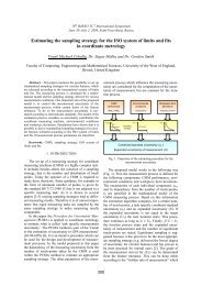
The ratio <strong>of</strong> <strong>the</strong> effective arias <strong>of</strong><br />
throttles, a = h/H<br />
Fig. 2. V1600 s/n 359. Dependence <strong>of</strong> <strong>the</strong> ratio α<br />
on a Reynolds number <strong>of</strong> incident flow<br />
If an ideal and an actual device have <strong>the</strong> same value <strong>of</strong><br />
<strong>the</strong> Euler number, <strong>the</strong>y are dynamically similar. The<br />
equality <strong>of</strong> Euler number in dynamically similar systems<br />
ensures <strong>the</strong> similarity <strong>of</strong> <strong>the</strong> pressure <strong>for</strong>ces.<br />
The calibration procedure states <strong>the</strong> necessity <strong>of</strong><br />
measuring <strong>the</strong> pressure Ps with respect to <strong>the</strong> relevant values<br />
<strong>of</strong> <strong>the</strong> output pressure P. From <strong>the</strong>se values <strong>the</strong> coefficient θ<br />
<strong>of</strong> <strong>the</strong> actual instrument can be determined by linear<br />
interpolation: Ps = (aP + b), as is shown graphically in<br />
Fig.3. Then, varying <strong>the</strong> coefficient α <strong>for</strong> <strong>the</strong> (3), using <strong>the</strong><br />
special s<strong>of</strong>tware, P s is obtained (5) <strong>of</strong> an ideal transducer<br />
with <strong>the</strong> same value <strong>of</strong> <strong>the</strong> slope: Psid = (aP + bid).<br />
Supply pressure Ps, Pa<br />
1.2<br />
1.0<br />
0.8<br />
0.6<br />
0.4<br />
0.2<br />
0.0<br />
16000<br />
12000<br />
8000<br />
4000<br />
a=(h/H)des<br />
a=( h/H)act<br />
0 25 50 75 100 125 150 175 200 225<br />
Reynolds number <strong>of</strong> <strong>the</strong> incident flow<br />
y = 1.0179x + 29.376<br />
R 2 = 1<br />
0<br />
0 4000 8000 12000 16000<br />
Output pressure P, Pa<br />
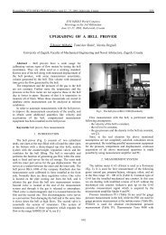
Fig.3. V1600 s/n 359. Dependence <strong>of</strong> actual supply<br />
pressure P s <strong>of</strong> divider on output pressure P<br />
The equation (5) written <strong>for</strong> <strong>the</strong> actual and <strong>for</strong> <strong>the</strong> ideal<br />
device is shown in tab. 1 (<strong>the</strong> measurements have been<br />
per<strong>for</strong>med <strong>for</strong> <strong>the</strong> V1600, S/N: 359):<br />
Table1<br />
V1600 s/n 359. Real device V1600 s/n 359. Ideal device<br />
P s = 1,0179 P + 29,376 P s = 1,0179 P + 28,967<br />
where: P s = 29,376 and P s = 28,967 – <strong>the</strong> pressure difference<br />
on <strong>the</strong> fixed throttle when is no piston on <strong>the</strong> nozzle, in <strong>the</strong><br />
real and respectively ideal case. The actual value measured<br />
by calibrator was P s = 28 Pa.<br />
The equality <strong>of</strong> <strong>the</strong> angular coefficients means <strong>the</strong> pistons <strong>of</strong><br />
<strong>the</strong> ideal and <strong>the</strong> actual device have identical displacement<br />
<strong>of</strong> <strong>the</strong> pistons with <strong>the</strong> change in pressure. Hence, <strong>the</strong><br />
requirement <strong>of</strong> geometrical similarity is respected.<br />
In order to calculate <strong>the</strong> ideal values <strong>of</strong> P s. , <strong>the</strong><br />
s<strong>of</strong>tware is using (3) and it is combining <strong>the</strong> ideal and <strong>the</strong><br />
actual characteristics <strong>of</strong> <strong>the</strong> divider.<br />
In <strong>the</strong> tab. 2 a discrepancy ∆P s = (P sact – P sid ) between<br />
<strong>the</strong> ideal and <strong>the</strong> experimental values <strong>of</strong> <strong>the</strong> supply pressure<br />
P s <strong>of</strong> <strong>the</strong> V1600 s/n 359 are shown:<br />
Table 2<br />
P n , Pa 20 100 120 200 700<br />
∆P s , Pa 0,1 -0,5 0,1 -0,6 0,3<br />
Continuation <strong>of</strong> Table 2<br />
P n , Pa 1000 3000 6000 10000 16000<br />
∆P s , Pa 4,3 21,1 21,9 10,7 -17,9<br />
The actual value <strong>of</strong> <strong>the</strong> supply pressure P s was<br />
measured by Druck calibrator DPI 145. The upper<br />
measuring limits <strong>of</strong> <strong>the</strong> two sensors are 0,5 bar and 1 bar<br />
and <strong>the</strong> uncertainty <strong>of</strong> <strong>the</strong> measured pressure (at 2 sigma<br />
level, determined by calibration) was less than 5 Pa.<br />
Equation (5) <strong>for</strong> <strong>the</strong> actual device s/n 359 and <strong>for</strong> its<br />
ma<strong>the</strong>matical model (10) is shown in tab.3:<br />
Table 3<br />
V1600 s/n 359. Real device V1600 s/n 359. Ideal device<br />
P s = 1,0179 P + 29,376 P s = 1,0179 P + 39,892<br />
As it is visible from table 3 at an output pressure Р=0<br />
Pa, <strong>the</strong> pressure drop on <strong>the</strong> fixed throttle obtained by using<br />
<strong>the</strong> frictional model (10) is with 10,5 Pa more than<br />
measured.<br />
For example <strong>the</strong> discrepancy ∆P s = (P sac – P sid )<br />
between <strong>the</strong> experimental values <strong>of</strong> supply pressure P s <strong>of</strong> <strong>the</strong><br />
V1600 s/n 359 and <strong>the</strong> values given by its ma<strong>the</strong>matical<br />
model (10) are shown in tab.4:<br />
Table 4<br />
P n , Pa 20 100 120 200 700<br />
∆P s , Pa 16,4 3,2 1,7 -5,5 -26,0<br />
Continuation <strong>of</strong> Table 4<br />
P n , Pa 1000 3000 6000 10000 16000<br />
∆P s , Pa -29,0 -29,5 -24,1 -11,6 8,0<br />
Dependence <strong>of</strong> design Euler’s criterion <strong>of</strong> two<br />
surveyed ma<strong>the</strong>matical models on actual Euler’s criterion <strong>of</strong><br />
V1600 s/n 359 is shown on Fig. 4.
Proceedings, XVII IMEKO World Congress, June 22 – 27, 2003, Dubrovnik, Croatia<br />
Proceedings, XVII IMEKO World Congress, June 22 – 27, 2003, Dubrovnik, Croatia<br />
TC1<br />
TC16<br />
Design Euler's criterion<br />
1.4<br />
1.2<br />
1.0<br />
0.8<br />
0.6<br />
0.4<br />
0.2<br />
Eudes<br />
EudesLam<br />
0.0<br />
0.0 0.2 0.4 0.6 0.8 1.0 1.2 1.4<br />
Actual Euler's criterion<br />
Fig. 4. V1600 s/n 359. The design Euler’s criterion<br />
versus actual Euler’s criterion<br />
The graph presented in Fig. 4 suggests clearly that <strong>the</strong><br />
gas streams, in <strong>the</strong> actual device and in its model based on<br />
Poiseuille’s law, are dynamically similar. The ma<strong>the</strong>matical<br />
model provide almost <strong>the</strong> same results with <strong>the</strong> real device<br />
when <strong>the</strong> losses <strong>of</strong> pressure are proportional to a quadrate <strong>of</strong><br />
velocity.<br />
In tab. 5, <strong>the</strong> values <strong>of</strong> <strong>the</strong> experimental and <strong>the</strong> design<br />
model (8) <strong>of</strong> Euler’s criterion <strong>for</strong> V1600 s/n 359 are<br />
presented:<br />
Table 5<br />
P n , Pa 20 100 120 200 700<br />
Eudes 1,39 0,30 0,25 0,16 0,06<br />
Euact 1,40 0,29 0,25 0,16 0,06<br />
Continuation <strong>of</strong> Table 5<br />
P n , Pa 1000 3000 6000 10000 16000<br />
Eudes 0,05 0,03 0,02 0,02 0,02<br />
Euact 0,05 0,04 0,03 0,02 0,02<br />
The V1600 s/n 359 was calibrated by comparison with<br />
<strong>the</strong> P7000 Pressurements standard (total uncertainty less<br />
<strong>the</strong>n 50 ppm,) at <strong>the</strong> pressure P c = 6 kPa. In <strong>the</strong> tab. 6 <strong>the</strong><br />
mean value <strong>of</strong> <strong>the</strong> difference between effective area A<br />
calculated using <strong>the</strong> old and <strong>the</strong> <strong>new</strong> method <strong>of</strong> calibration,<br />
from <strong>the</strong> values A, obtained by direct comparison <strong>of</strong> <strong>the</strong><br />
V1600 with <strong>the</strong> P7000 standard are shown in tab.6:<br />
Table 6<br />
(A old – A <strong>new</strong> )/ A <strong>new</strong> , %<br />
P n , kPa Old method New method σ, %<br />
8 0,006 0,003 0,0003<br />
10 0,007 0,002 0,0006<br />
12 0,008 0,001 0,0006<br />
14 0,007 -0,002 0,0005<br />
16 0,009 -0,002 0,0006<br />
where: σ - standard deviation <strong>of</strong> <strong>the</strong> mean.<br />
The data presented in <strong>the</strong> tab.6 was confirmed by <strong>the</strong><br />
calibration results <strong>of</strong> many V1600 instruments, which have<br />
been carried out at Pressurements and VNIIMS.<br />
The V1600 is rapidly gaining recognition and<br />
acceptation as a standard <strong>for</strong> low-pressure calibrations at<br />
various levels <strong>of</strong> <strong>the</strong> calibration hierarchy.<br />
Conclusion<br />
An important part <strong>of</strong> <strong>the</strong> calibration uncertainty <strong>of</strong> <strong>the</strong><br />
effective area <strong>of</strong> <strong>the</strong> V1600 has been caused by a methodical<br />
error <strong>of</strong> measuring <strong>the</strong> pressure difference on <strong>the</strong> fixed<br />
throttle <strong>of</strong> <strong>the</strong> <strong>pneumatic</strong> transducer.<br />
The <strong>new</strong> calibration approach is based on <strong>the</strong> equality<br />
<strong>of</strong> <strong>the</strong> Eulerian criterion <strong>of</strong> <strong>the</strong> actual device and its<br />
ma<strong>the</strong>matical model <strong>for</strong> a quadratic dependence between <strong>the</strong><br />
pressure difference on <strong>the</strong> fixed throttle and flow rate.<br />
This <strong>new</strong> approach is permitting <strong>the</strong> use <strong>of</strong> <strong>the</strong> supply<br />
pressure provided by <strong>the</strong> ma<strong>the</strong>matical model <strong>for</strong> <strong>the</strong><br />
calibration <strong>of</strong> V1600’s effective area.<br />
This method allows an essential increase <strong>of</strong> <strong>the</strong><br />
calibration <strong>accuracy</strong> <strong>of</strong> V1600 instrument within <strong>the</strong> range 3<br />
kPa to 16 kPa.<br />
REFERENCES<br />
[1] “Users handbook. Portable, low pressure <strong>pneumatic</strong> deadweight<br />
testers”, Pressurements Ltd, Dunstable, Bed<strong>for</strong>dshire,<br />
England.<br />
[2] S. M. Kesselman, “The calibrator <strong>of</strong> pressure "Vozdukh". A<br />
Path<strong>way</strong> to <strong>accuracy</strong>”, Legal and applied metrology, no. 4,<br />
pp.25-28, April 1993.<br />
[3] V. N .Constantinescu, “Gas lubrication”, Machine building,<br />
pp.45-47, Moscow,1968.<br />
[4] A. I. Bogomolov, K. A Mikhailov, “Hydraulics’, Stroyizdat,<br />
pp.97-98, Moscow, 1972<br />
Authors:<br />
M. Bryant<br />
Commercial Director, GE Druck Holdings p.l.c Fir Tree<br />
Lane Groby Leicester LE6 0FH<br />
phone: 0116 231 7100<br />
fax: 0116 287 1460<br />
e-mail:bryantm@druck.com<br />
N. Moisoi<br />
Head <strong>of</strong> Laboratory, Pressurements Limited,<br />
Unit 22, Apex Business Centre, Boscombe<br />
Road, Dunstable Beds, LU5 4SB, England,<br />
phone: +44 (0) 1582 474535<br />
fax: +44 (0) 1582 601185<br />
e-mail: moisoin@pressurements.com<br />
S. M. Kesselman<br />
Head <strong>of</strong> Pressure Laboratory, Russian Research<br />
Institute <strong>for</strong> metrological Service (VNIIMS), 46<br />
Ozernaya, G-361, Moscow, 119361, Russia,<br />
phone: (095) 422-0636<br />
fax (095) 437-5666<br />
e-mail: kesstella@cnt.ru