new way of accuracy improvement for the pneumatic ... - imeko
new way of accuracy improvement for the pneumatic ... - imeko
new way of accuracy improvement for the pneumatic ... - imeko

Create successful ePaper yourself
Turn your PDF publications into a flip-book with our unique Google optimized e-Paper software.
Proceedings, XVII IMEKO World Congress, June 22 – 27, 2003, Dubrovnik, Croatia<br />
Proceedings, XVII IMEKO World Congress, June 22 – 27, 2003, Dubrovnik, Croatia<br />
TC1<br />
TC16<br />
The effective area <strong>of</strong> V1600 can be determined by<br />
direct comparison with a pressure standard <strong>of</strong> a higher<br />
<strong>accuracy</strong>.<br />
The problem arises when it is necessary to calibrate or<br />
to test pressure instruments with an uncertainty less than<br />
(0,05 – 0,1) Pa in <strong>the</strong> range below 3000 Pa, where very <strong>of</strong>ten<br />
it is not possible to determine <strong>the</strong> effective area by direct<br />
comparison.<br />
There<strong>for</strong>e <strong>the</strong> effective area <strong>of</strong> each V1600 is<br />
determined accordingly with <strong>the</strong> original method <strong>of</strong><br />
calibration described in [2]. This method is based on<br />
definition <strong>of</strong> effective area A c , at a pressure P c ,<br />
corresponding to <strong>the</strong> mass M c (including piston, carrier and<br />
weights), within its range, which is accessible to <strong>the</strong><br />
available standard, <strong>for</strong> example: 3, 6 or 16 kPa.<br />
The equation <strong>of</strong> calibration is given by:<br />
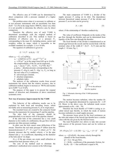
The main component <strong>of</strong> V1600 is a divider <strong>of</strong> <strong>the</strong><br />
supply pressure P s acting on its inlet. The dependence<br />
between <strong>the</strong>oretical output pressure P <strong>of</strong> <strong>the</strong> divider and<br />
pressure P s on its inlet can be given by:<br />
P s = θ P, (5)<br />
where: θ -<strong>the</strong> relationship <strong>of</strong> throttles conductivity.<br />
The value <strong>of</strong> coefficient θ depends on <strong>the</strong> modes <strong>of</strong> <strong>the</strong><br />
gas flow through <strong>the</strong> throttles and can be determined from<br />
equality <strong>of</strong> <strong>the</strong> flow rate through <strong>the</strong> throttles.<br />
The fixed throttle <strong>of</strong> <strong>the</strong> divider is manufactured as an<br />
annual gap between <strong>the</strong> nozzle and <strong>the</strong> nozzle-body with <strong>the</strong><br />
nominal value <strong>of</strong> <strong>the</strong> width H = (0,15 – 0,17) mm and <strong>the</strong><br />
length L =10 mm, Fig. 1.<br />
A j = A c [1 – q c (q c /q j – 1)] (4)<br />
where: q c = G c υ c Cosβ/M c g,<br />
υ c = {[2kRT/(k-1)]*[1 – (p a /p) (k-1)/k ]} 1/2 or<br />
υ c =(2P/ρ) 1/2 as in <strong>the</strong> range from 0,02 up to 16 kPa<br />
<strong>the</strong> compressibility <strong>of</strong> <strong>the</strong> air can be neglected,<br />
q j /q c = {(p j /p c ) 1/k [(P sj - P j )/(P sc - P c )]*(M c M j )} 1/2<br />
p j and p c – absolute pressure corresponding to <strong>the</strong><br />
pressure P c ∼M c g/A 0 and P j ∼ M j g/ A 0 , P sj , as long as<br />
<strong>the</strong> real value <strong>of</strong> A 0 is unknown,<br />
R - universal gas constant,<br />
T - absolute temperature,<br />
k – adiabatic index.<br />
The analysis <strong>of</strong> <strong>the</strong> calibration results from several<br />
instruments has shown that <strong>the</strong> relative <strong>accuracy</strong>, due to<br />
calibration method, begins to increase at 700 Pa and reaches<br />
up to 0,009 % at 16 kPa.<br />
The purpose <strong>of</strong> this paper is to present <strong>the</strong> original<br />
manner <strong>of</strong> detection and elimination <strong>of</strong> above mentioned<br />
systematic error.<br />
New <strong>way</strong> <strong>of</strong> <strong>accuracy</strong> <strong>improvement</strong> <strong>for</strong> <strong>the</strong> V1600<br />
This behavior <strong>of</strong> <strong>the</strong> calibration results can to be<br />
explained by both local and travelling losses, which<br />
inevitably arise at measuring pressure P sj at its origin place.<br />
The essential losses are created by <strong>the</strong> connector found<br />
between <strong>the</strong> manometer <strong>for</strong> measurings Ps and <strong>the</strong> pipeline.<br />
The inlet hole <strong>of</strong> <strong>the</strong> connector should be<br />
perpendicularly to an interior wall <strong>of</strong> <strong>the</strong> pipeline channel.<br />
If <strong>the</strong> inlet hole <strong>of</strong> <strong>the</strong> connection has a very small<br />
diameter (a few tenths <strong>of</strong> a millimetre), <strong>the</strong> gas flow will not<br />
generate any false pressure readings.<br />
In o<strong>the</strong>r case <strong>the</strong> hole causes some deflections <strong>of</strong> <strong>the</strong><br />
stream. There<strong>for</strong>e <strong>the</strong> real static pressure P′ differs from <strong>the</strong><br />
measured pressure P s : P′ = P s ± χρυ′ 2 /2, where: ρυ′ 2 /2 – <strong>the</strong><br />
dynamic pressure due by medial velocity υ′ in <strong>the</strong> pipe<br />
channel and χ - is a coefficient, depending on <strong>the</strong> diameter<br />
<strong>of</strong> <strong>the</strong> hole and <strong>of</strong> its shape.<br />
At χ >0 <strong>the</strong> gas stream can create small refraction or<br />
contrariwise back pressure when χ