Panel 327 - Calira
Panel 327 - Calira
Panel 327 - Calira

Create successful ePaper yourself
Turn your PDF publications into a flip-book with our unique Google optimized e-Paper software.
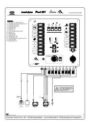
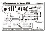
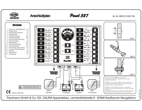
Stromkreise<br />
1 = Topp. bzw. Dreifarbenlicht<br />
2 = Dampferlicht<br />
3 = Beleuchtung Bug/Heck<br />
4 = Salingleuchte<br />
5 = Innenbeleuchtung<br />
6 = Innenbeleuchtung<br />
7 = Instrumentenbeleuchtung<br />
8 = Echolot/Sumlog<br />
9 = Bilgenpumpe<br />
10 = Frischwasserpumpe<br />
11 = Abwasserpumpe<br />
12 = Ankerwinde (Steuerstrom)<br />
13 = Autopilot/Windmeßanlage<br />
14 = Heizung<br />
15 = Kühlschrank<br />
16 = Funkanlage<br />
Made in Germany<br />
3A<br />
3A<br />
7A<br />
7A<br />
10A<br />
10A<br />
3A<br />
3A<br />
10A<br />
10A<br />
10A<br />
3A<br />
7A<br />
4A<br />
12A<br />
7A<br />
Anschlußplan <strong>Panel</strong> <strong>327</strong> Art.-Nr. H08 012 0<strong>327</strong> 00<br />
1<br />
2<br />
3<br />
4<br />
5<br />
6<br />
7<br />
8<br />
ws 1<br />
br ¾<br />
gn ½<br />
ge ¼<br />
gr 0<br />
Tank II<br />
(Abwasser)<br />
0<br />
10<br />
1/4<br />
0<br />
12<br />
Tank<br />
14<br />
1/2 3/4<br />
1/1<br />
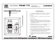
<strong>Panel</strong> <strong>327</strong><br />
5pol. 1 3pol. 5pol.<br />
5 5<br />
2A<br />
16<br />
100A<br />
2A<br />
9<br />
10<br />
11<br />
12<br />
13<br />
14<br />
15<br />
16<br />
m - 0 - a<br />
Made in Germany<br />
ws 1<br />
br ¾<br />
gn ½<br />
ge ¼<br />
gr 0<br />
Tank I<br />
(Frischwasser)<br />
9,5-10mm<br />
In die Tanks Löcher mit 9,5-10,0mm bohren.<br />
Bohrungen von außen, und möglichst auch von innen,<br />
entgraten (siehe Bild 1)<br />
Bild 1<br />
Bild 2<br />
Bild 3<br />
Meßfühler zusammensetzen (Bild 2), Schrauben dabei mit<br />
Dichtmasse oder elastischem Kleber einsetzen, Schrauben<br />
zunächst nur lose von Hand anziehen.<br />
Meßfühler in die Tankbohrung einsetzen -Kabelfarben<br />
beachten- und mit Schraubendreher fest anziehen. Der Rand<br />
der Gummidichtung<br />
wird dabei gegen die Außenwand des Tanks gepreßt.<br />
Innen bildet sich eine Gummiwulst, welche die Bohrung<br />
Trautmann GmbH & Co. KG CALIRA-Apparatebau Lerchenfeldstraße 9 87600 Kaufbeuren-Neugablonz
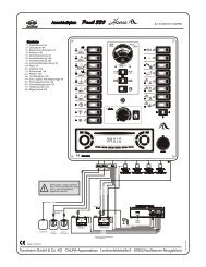
Consumer circuits<br />
1 = Masthead light<br />
2 = Steaming light<br />
3 = Lighting prow/stern<br />
4 = Deck light<br />
5 = Interior lights<br />
6 = Interior lights<br />
7 = Instrument lighting<br />
8 = Echolot/Sumlog<br />
9 = Bilge pump<br />
10 = Freshwater pump<br />
11 = Waste water pump<br />
12 = Anchor windlass (control)<br />
13 = Autopilot/Windmeas.<br />
14 = Heating<br />
15 = Refrigerator<br />
16 = Radio<br />
Made in Germany<br />
3A<br />
3A<br />
7A<br />
7A<br />
10A<br />
10A<br />
3A<br />
3A<br />
10A<br />
10A<br />
10A<br />
3A<br />
7A<br />
4A<br />
12A<br />
7A<br />
Connection diagram <strong>Panel</strong> <strong>327</strong> Art.-Nr. H08 012 0<strong>327</strong> 00<br />
Fuses must be assembled near to the<br />
+poles of the batteries<br />
1<br />
2<br />
3<br />
4<br />
5<br />
6<br />
7<br />
8<br />
WH 1<br />
BN ¾<br />
GN ½<br />
YE ¼<br />
GY 0<br />
Tank II<br />
(waste water)<br />
Consumer<br />
12Volt (8x)<br />
0<br />
10<br />
1/4<br />
0<br />
12<br />
Tank<br />
14<br />
1/2 3/4<br />
1/1<br />
<strong>Panel</strong> <strong>327</strong><br />
5pol. 1 3pol. 5pol.<br />
5 5<br />
0,25mm² BU<br />
2A<br />
0,25mm² PK<br />
0,25mm² RD<br />
Battery 12V<br />
16<br />
100A<br />
2A<br />
Battery 12V<br />
9<br />
10<br />
11<br />
12<br />
13<br />
14<br />
15<br />
16<br />
m - 0 - a<br />
WH 1<br />
BN ¾<br />
GN ½<br />
YE ¼<br />
GY 0<br />
Made in Germany<br />
Consumer<br />
12Volt (8x)<br />
(service) (motor start)<br />
Tank I<br />
(fresh water)<br />
9,5-10mm<br />
Drill holes into the tanks with 9,5-10,0mm diameter.<br />
Burr the holes from both sides. (Pic. 1)<br />
Compose the sensor (Pic. 2), insert the screw with sealing<br />
compound and fasten srews first only by hand.<br />
Picture 1<br />
Picture 2<br />
Picture 3<br />
Insert the sensor into the hole in the tank and fasten it with a<br />
screw driver. Note the wire colours. The edge of the rubber<br />
gasket is pressed against the outer surface of the tank. Inside<br />
the tank it forms a rubber fold , which seals up the hole sure.<br />
Trautmann GmbH & Co. KG CALIRA-Apparatebau Lerchenfeldstraße 9 87600 Kaufbeuren-Neugablonz