Formal Safety Analysis and Verification in the Model ... - TU Clausthal
Formal Safety Analysis and Verification in the Model ... - TU Clausthal
Formal Safety Analysis and Verification in the Model ... - TU Clausthal

You also want an ePaper? Increase the reach of your titles
YUMPU automatically turns print PDFs into web optimized ePapers that Google loves.
<strong>Formal</strong> <strong>Safety</strong> <strong>Analysis</strong> <strong>and</strong> <strong>Verification</strong> <strong>in</strong> <strong>the</strong><br />
<strong>Model</strong> Driven Development of a Pacemaker Product L<strong>in</strong>e<br />
Sara Bessl<strong>in</strong>g Michaela Huhn<br />
Department of Informatics, <strong>Clausthal</strong> University of Technology<br />
38678 <strong>Clausthal</strong>-Zellerfeld, Germany<br />
{Sara.Bessl<strong>in</strong>g|Michaela.Huhn}@tu-clausthal.de<br />
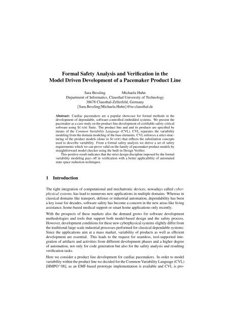
Abstract: Cardiac pacemakers are a popular showcase for formal methods <strong>in</strong> <strong>the</strong><br />
development of dependable, software-controlled embedded systems. We present <strong>the</strong><br />
pacemaker as a case study on <strong>the</strong> product-l<strong>in</strong>e development of certifiable safety-critical<br />
software us<strong>in</strong>g SCADE Suite. The product l<strong>in</strong>e <strong>and</strong> <strong>and</strong> its products are specified by<br />
means of <strong>the</strong> Common Variability Language (CVL). CVL separates <strong>the</strong> variability<br />
model<strong>in</strong>g from <strong>the</strong> doma<strong>in</strong> model<strong>in</strong>g of <strong>the</strong> base elements. CVL enforces a strict structur<strong>in</strong>g<br />
of <strong>the</strong> product models (done <strong>in</strong> SCADE) that reflects <strong>the</strong> substitution concepts<br />
used to describe variability. From a formal safety analysis we derive a set of safety<br />
requirements which we can prove valid on <strong>the</strong> family of pacemaker product models by<br />
straightforward model checker us<strong>in</strong>g <strong>the</strong> built-<strong>in</strong> Design Verifier.<br />
This positive result <strong>in</strong>dicates that <strong>the</strong> strict design discipl<strong>in</strong>e imposed by <strong>the</strong> formal<br />
variability model<strong>in</strong>g pays off <strong>in</strong> verification with a better applicability of automated<br />
state space reduction techniques.<br />
1 Introduction<br />
The tight <strong>in</strong>tegration of computational <strong>and</strong> mechatronic devices, nowadays called cyberphysical<br />
systems, has lead to numerous new applications <strong>in</strong> multiple doma<strong>in</strong>s. Whereas <strong>in</strong><br />
classical doma<strong>in</strong>s like transport, defense or <strong>in</strong>dustrial automation, dependability has been<br />
a key issue for decades, software safety has become a concern <strong>in</strong> <strong>the</strong> new areas like liv<strong>in</strong>g<br />
assistance, home-based medical support or smart home applications only recently.<br />
With <strong>the</strong> prospects of <strong>the</strong>se markets also <strong>the</strong> dem<strong>and</strong> grows for software development<br />
methodologies <strong>and</strong> tools that support both model-based design <strong>and</strong> <strong>the</strong> safety process.<br />
However, development conditions for <strong>the</strong>se new cyberphysical systems slightly differ from<br />
<strong>the</strong> traditional large scale <strong>in</strong>dustrial processes performed for classical dependable systems:<br />
S<strong>in</strong>ce <strong>the</strong> applications aim at a mass market, variability of products as well as efficient<br />
development are essential. This leads to <strong>the</strong> request for seamless, tool-supported <strong>in</strong>tegration<br />
of artifacts <strong>and</strong> activities from different development phases <strong>and</strong> a higher degree<br />
of automation, not only for code generation but also for <strong>the</strong> safety analysis <strong>and</strong> result<strong>in</strong>g<br />
verification tasks.<br />
Here we consider a product l<strong>in</strong>e development for cardiac pacemakers. In order to model<br />
variability with<strong>in</strong> <strong>the</strong> product l<strong>in</strong>e we decided for <strong>the</strong> Common Variability Language (CVL)<br />
[HMPO + 08], as an EMF-based prototype implementation is available <strong>and</strong> CVL is pro-
posed for st<strong>and</strong>ardization by <strong>the</strong> OMG. Even more important, CVL separates <strong>the</strong> variability<br />
model<strong>in</strong>g from <strong>the</strong> doma<strong>in</strong> model<strong>in</strong>g used to design <strong>the</strong> base elements of <strong>the</strong> product<br />
l<strong>in</strong>e. For <strong>the</strong> doma<strong>in</strong> model we use <strong>the</strong> SCADE Suite as development framework, s<strong>in</strong>ce<br />
SCADE is qualified for <strong>the</strong> design of certifiable, dependable software [Est09] <strong>and</strong> provides<br />
a ready to market automated verification facilities. Our motivation for apply<strong>in</strong>g a systematic<br />
product l<strong>in</strong>e approach on <strong>the</strong> family of pacemaker orig<strong>in</strong>s from <strong>the</strong> disillusion<strong>in</strong>g results<br />
for automated verification we experienced <strong>in</strong> previous work [HB11, DHM11]: Even<br />
for medium size <strong>in</strong>dustrial design models, fully automated verification yields only very<br />
few results due to complexity problems but most properties could be proven only when<br />
apply<strong>in</strong>g advanced abstraction techniques manually. Thus <strong>the</strong> question arises whe<strong>the</strong>r <strong>the</strong><br />
strict structur<strong>in</strong>g <strong>and</strong> <strong>the</strong> formally def<strong>in</strong>ed replacements <strong>and</strong> substitutions needed for <strong>the</strong><br />
product l<strong>in</strong>e specification will have a (hopefully positive) impact on verification tasks. The<br />
rationale for that is that product l<strong>in</strong>e systematics will be reflected <strong>in</strong> <strong>the</strong> design <strong>and</strong> give<br />
structural <strong>in</strong>sights how to decompose safety requirements <strong>and</strong> where to apply verification<br />
heuristics <strong>in</strong> <strong>the</strong> design model for <strong>the</strong> products.<br />
The contribution of this paper is twofold: (1) We model a pacemaker product l<strong>in</strong>e by us<strong>in</strong>g<br />
CVL for <strong>the</strong> variability model<strong>in</strong>g <strong>and</strong> SCADE to model <strong>the</strong> doma<strong>in</strong>. (2) We provide a<br />
showcase for <strong>the</strong> efficiency ga<strong>in</strong> one may obta<strong>in</strong> from a strict product l<strong>in</strong>e design approach<br />
<strong>in</strong> <strong>the</strong> subsequent verification: We can easily prove a set of safety requirements to be valid<br />
for <strong>the</strong> pacemaker variants by fully automated model check<strong>in</strong>g.<br />
The rest of <strong>the</strong> paper is organized as follows: Sec. 2 sketches <strong>the</strong> basics. The pacemaker<br />
is <strong>in</strong>troduced <strong>in</strong> Sec. 3. Sec. 4 describes <strong>the</strong> design of a product l<strong>in</strong>e for a family of<br />
pacemakers for which safety analysis <strong>and</strong> verification is presented <strong>in</strong> Sec. 5. In Sec. 6 we<br />
conclude.<br />
2 Background<br />
2.1 CVL - Common Variability Language<br />
The Common Variability Language (CVL) [HMPO + 08]<br />
is an approach to specify product l<strong>in</strong>es upon a doma<strong>in</strong><br />
specific model<strong>in</strong>g language (DSL). CVL adds <strong>the</strong> possibility<br />
to model product l<strong>in</strong>es or product variabilities on<br />
<strong>the</strong>se models. To be able to model a product l<strong>in</strong>e with<br />
CVL one has to underst<strong>and</strong> first <strong>the</strong> different layers of<br />
CVL (see fig. 1). The variability model of CVL consists<br />
of two layers, <strong>the</strong> feature specification layer (FSL) <strong>and</strong><br />
<strong>the</strong> product realization layer (PRL). In <strong>the</strong> FSL <strong>the</strong> elements<br />
def<strong>in</strong><strong>in</strong>g a particular product variability are specified<br />
Figure 1: CVL layers, source:<br />
from a user’s po<strong>in</strong>t of view. The PRL consists of <strong>the</strong> [cvl10]<br />
def<strong>in</strong>itions needed to build one product of <strong>the</strong> product l<strong>in</strong>e from <strong>the</strong> base models <strong>and</strong> <strong>the</strong>ir<br />
modifications. Beneath FSL <strong>and</strong> <strong>the</strong> PRL <strong>the</strong> base model has to be provided as <strong>the</strong> start<strong>in</strong>g
po<strong>in</strong>t of <strong>the</strong> product l<strong>in</strong>e from which all possible product variabilities are derived. The base<br />
model <strong>and</strong> <strong>the</strong> library models are modeled <strong>in</strong> a DSL or UML. A s<strong>in</strong>gle product variability<br />
is described by a resolution model, <strong>the</strong> last element of <strong>the</strong> CVL layers. A resolution model<br />
consists of a subset of elements of <strong>the</strong> PRL <strong>and</strong> FSL. With <strong>the</strong> help of <strong>the</strong>se resolution<br />
models, new variability models can be created by a model-to-model transformation.<br />
2.2 The SCADE Tool Suite<br />
The acronym SCADE st<strong>and</strong>s for <strong>Safety</strong>-Critical Application Development Environment.<br />
The ma<strong>in</strong> objectives of <strong>the</strong> SCADE Suite are (1) to support systematic, model-based development<br />
of correct software based on formal methods <strong>and</strong> (2) to cover <strong>the</strong> whole development<br />
process [Est09]. The language Scade underly<strong>in</strong>g <strong>the</strong> tool is data-flow oriented. Its<br />
formal semantics is based on a synchronous model of computation, i.e. cyclic execution of<br />
<strong>the</strong> model. The SCADE Suite is an <strong>in</strong>tegrated development environment that covers many<br />
development activities like model<strong>in</strong>g, formal verification us<strong>in</strong>g <strong>the</strong> SAT-based SCADE Design<br />
Verifier [ADS + 04], certified automatic code generation, requirements trac<strong>in</strong>g, simulation<br />
<strong>and</strong> test<strong>in</strong>g on <strong>the</strong> code level, <strong>in</strong>clusive coverage metrics.<br />
2.3 Deductive Cause Consequence <strong>Analysis</strong><br />
A major goal <strong>in</strong> safety analysis is to determ<strong>in</strong>e how faults modes at <strong>the</strong> component level<br />
causally relate to system hazards. Among <strong>the</strong> various formally founded techniques proposed<br />
for this task we have selected Deductive Cause Consequence <strong>Analysis</strong> (DCCA) by<br />
Ortmeier et al. [ORS06, GOR07], because DCCA does not only formalize techniques like<br />
FTA (Fault Tree <strong>Analysis</strong>) <strong>and</strong> an FMEA (Failure Mode <strong>and</strong> Effect <strong>Analysis</strong>) [IEC06],<br />
which are well-established <strong>and</strong> recommended by <strong>the</strong> st<strong>and</strong>ards. In addition, <strong>the</strong> identified<br />
fault modes <strong>and</strong> hazards can be reused <strong>in</strong> safety assurance to formally verify that sufficient<br />
measures have been taken to prevent <strong>the</strong> identified hazards (for details <strong>and</strong> formalization<br />
see [GOR07, DHM11]). Hazards are specified as observer nodes that read signals from<br />
<strong>the</strong> control logic <strong>and</strong> evaluate <strong>the</strong>m accord<strong>in</strong>g to <strong>the</strong> negation of <strong>the</strong> hazard predicate.<br />
2.4 Related Work<br />
S<strong>in</strong>ce PACEMAKER <strong>Formal</strong> Methods Challenge [Sci07], pacemakers were <strong>in</strong>vestigated<br />
<strong>in</strong>tensively with<strong>in</strong> <strong>the</strong> formal methods community. For brevity, we only refer to three<br />
of <strong>the</strong>m: Jee, Lee, <strong>and</strong> Sokolsky worked on assurance cases of <strong>the</strong> pacemaker software<br />
[JLS10]. They focused on <strong>the</strong> basic VVI mode, <strong>and</strong> employed UPPAAL for both, design<br />
<strong>and</strong> verification. In [TZT10] <strong>the</strong> authors used timed CSP to specify a number of pacemaker<br />
modes <strong>and</strong> to verify several tim<strong>in</strong>g constra<strong>in</strong>ts for <strong>the</strong>m. Liu et al. [LDL07] explicitly<br />
model a product l<strong>in</strong>e of pacemakers <strong>and</strong> address its safety analysis.
3 The Pacemaker<br />
3.1 The Human Heart<br />
From a bio-mechanical po<strong>in</strong>t of view, <strong>the</strong> human heart is <strong>the</strong> pump of <strong>the</strong> circulatory<br />
system. It consists of two atria <strong>and</strong> two ventricles. The contraction of <strong>the</strong> heart is <strong>in</strong>itiated<br />
at <strong>the</strong> so-called s<strong>in</strong>oatrial node (SA node), an area of self-excitable cells with<strong>in</strong> <strong>the</strong> right<br />
atrium known as P wave. The electrical impulses spread through <strong>the</strong> atria <strong>and</strong> ventricles<br />
with a dedicated tim<strong>in</strong>g characteristics (see <strong>the</strong> electrocardiogram (EKG) shown <strong>in</strong> Fig. 2),<br />
<strong>the</strong>reby caus<strong>in</strong>g <strong>the</strong> contraction of <strong>the</strong> chambers.<br />
Nowadays, a too low or sporadically miss<strong>in</strong>g pulse generation by <strong>the</strong> SA node, called<br />
bradycardia, <strong>and</strong> defects <strong>in</strong> <strong>the</strong> cardiac conduction system are cured by an implanted artificial<br />
cardiac pacemaker. Artificial pacemakers have to respect <strong>the</strong> tim<strong>in</strong>g characteristics<br />
of <strong>the</strong> s<strong>in</strong>us rhythms as <strong>the</strong>y are critical. Foremost, pulses must not be generated with<strong>in</strong><br />
<strong>the</strong> refractory <strong>in</strong>tervals after depolarization, as this may cause life-threaten<strong>in</strong>g cardiac fibrillation.<br />
3.2 Informal Specification of Pacemakers<br />
The most complex pacemakers are variants of<br />
<strong>the</strong> modern DDD mode [Sci07]. Here we<br />
consider a family of pacemakers with <strong>the</strong> aim<br />
to build a product l<strong>in</strong>e out of <strong>the</strong>m. The<br />
functions of a pacemaker are given by a sequence<br />
of letters accord<strong>in</strong>g to <strong>the</strong> <strong>in</strong>ternational<br />
NASPE/BPEG Code [BDF + 02].<br />
The simplest pacemakers stimulate <strong>the</strong> heart,<br />
whenever a timer expires without sens<strong>in</strong>g <strong>the</strong><br />
natural pace. The A00 <strong>and</strong> V00 mode stimulate<br />
ei<strong>the</strong>r <strong>the</strong> atrium or ventricle, respectively. The<br />
D00 stimulates both, atrium <strong>and</strong> ventricle. For<br />
this, it has two consecutive timers monitor<strong>in</strong>g<br />
a modified base <strong>in</strong>terval (BI) <strong>and</strong> <strong>the</strong> AV <strong>in</strong>terval<br />
(AVI). The AVI is <strong>the</strong> time between an atrial<br />
impulse <strong>and</strong> a ventricle one. The modified BI of<br />
D00 is <strong>the</strong> time between a ventricle impulse <strong>and</strong><br />
an atrial one.<br />
Todays most common mode is <strong>the</strong> VVI mode. It<br />
only stimulates <strong>the</strong> heart - <strong>in</strong> case of <strong>the</strong> VVI of<br />
<strong>the</strong> ventricle - when <strong>the</strong> natural pace is miss<strong>in</strong>g.<br />
The VVI uses a timer for <strong>the</strong> base <strong>in</strong>terval as<br />
well to trigger pulse generation. The BI of <strong>the</strong><br />
Figure 2: Intervals of pacemaker variants
VVI is <strong>the</strong> maximal time between two ventricular paces. But <strong>the</strong> BI is reset if a natural<br />
pace of <strong>the</strong> ventricle is detected <strong>and</strong> no stimulation takes place <strong>in</strong> this case. After each<br />
artificial or natural pace <strong>the</strong> pacemaker starts a refractory period <strong>in</strong> which no detection or<br />
stimulation can occur. The pacemaker mode AAI functions analogously for <strong>the</strong> atrium.<br />
DDD means dual pac<strong>in</strong>g, dual sens<strong>in</strong>g, <strong>and</strong> dual response mode, see <strong>the</strong> NASPE/BPEG<br />
code. A DDD pacemaker senses both right chambers <strong>and</strong> can also stimulate <strong>the</strong>m both,<br />
if no natural pulses are detected. The DDD pacemaker uses two timers for each chamber.<br />
The AVI is <strong>the</strong> time between an atrial pace <strong>and</strong> a ventricular one, <strong>the</strong> BI is <strong>the</strong> time between<br />
two atrial paces. Moreover, <strong>the</strong> DDD mode adapts <strong>the</strong> AVI (so-called AV hysteresis) for<br />
<strong>the</strong> next cycle, <strong>in</strong> case a stimulation occurs <strong>and</strong> it is able to h<strong>and</strong>le a ventricular extrasystole<br />
(VES), i.e. an additional ventricle pace occurr<strong>in</strong>g <strong>in</strong> a particular <strong>in</strong>terval. The DDD<br />
pacemaker also implements o<strong>the</strong>r modes: In case of a battery voltage drop it switches to<br />
VVI mode <strong>in</strong> order to save energy. The D00 mode is also <strong>in</strong>tegrated for usage dur<strong>in</strong>g a<br />
magnet test, which may be performed by a doctor to check <strong>the</strong> pacemaker’s function. The<br />
s<strong>in</strong>gle <strong>in</strong>tervals of each pacemaker are illustrated <strong>in</strong> Fig. 2.<br />
4 Creat<strong>in</strong>g a Product L<strong>in</strong>e of Pacemakers<br />
4.1 Pacemaker <strong>Model</strong><strong>in</strong>g Objects<br />
Pacemakers are constructed <strong>in</strong> several variants, differ<strong>in</strong>g <strong>in</strong> possible features <strong>and</strong> functions.<br />
Fur<strong>the</strong>rmore, enhanced pacemakers implement simpler ones as an emergency or diagnostic<br />
mode. Thus a product l<strong>in</strong>e built from <strong>the</strong> various modes is helpful to illustrate <strong>the</strong>se<br />
relations <strong>and</strong> even more important to simplify <strong>the</strong> model<strong>in</strong>g of <strong>the</strong> pacemaker modes.<br />
In order to create a product l<strong>in</strong>e due to [cvl10], first we have to identify <strong>the</strong> base elements<br />
of <strong>the</strong> pacemaker modes. We start with <strong>the</strong> simplest modes, <strong>the</strong> A00 or V00 pacemaker<br />
which consist of <strong>the</strong> same model<strong>in</strong>g objects. The A00 <strong>and</strong> <strong>the</strong> V00 differ only <strong>in</strong> <strong>the</strong> length<br />
of <strong>the</strong> base <strong>in</strong>terval which is a s<strong>in</strong>gle property of a model<strong>in</strong>g object. So we identify <strong>the</strong><br />
follow<strong>in</strong>g three model<strong>in</strong>g objects which are depicted <strong>in</strong> Fig. 3:<br />
• Timer: starts at zero <strong>and</strong> <strong>in</strong>crements by one at each cycle<br />
• Reset: resets <strong>the</strong> timer to zero when it reaches <strong>the</strong> end of <strong>the</strong> base <strong>in</strong>terval<br />
• Output: stimulates <strong>the</strong> heart chamber whenever a reset occurs<br />
Start<strong>in</strong>g with <strong>the</strong>se three base elements we<br />
study <strong>the</strong> D00 pacemaker. For each heart<br />
chamber we can reuse <strong>the</strong> known model<strong>in</strong>g<br />
objects but we have to adapt <strong>the</strong><br />
timer <strong>in</strong>terval to <strong>the</strong> atrium ventricle <strong>in</strong>terval<br />
(AVI). Fur<strong>the</strong>rmore, we decide to rename<br />
when doubl<strong>in</strong>g <strong>the</strong> objects because<br />
Figure 3: Schematic use of model<strong>in</strong>g objects to<br />
build an A00 pacemaker
of clarity. The timeout of <strong>the</strong> second timer is set to <strong>the</strong> sum of <strong>the</strong> BI <strong>and</strong> AVI because we<br />
can use <strong>the</strong> reset this way without changes. To model <strong>the</strong> consecutive order of <strong>the</strong> BI <strong>and</strong><br />
AVI <strong>in</strong>terval we <strong>in</strong>sert a new element, <strong>the</strong> block. It blocks <strong>the</strong> restart of <strong>the</strong> AVI timer until<br />
<strong>the</strong> reset of <strong>the</strong> second timer occurs.<br />
Figure 4: UML model of AAI pacemaker<br />
Next we consider <strong>the</strong> AAI <strong>and</strong> VVI pacemaker, respectively. The AAI <strong>and</strong> VVI pacemaker<br />
co<strong>in</strong>cide regard<strong>in</strong>g <strong>the</strong> model<strong>in</strong>g objects as well as <strong>the</strong> base <strong>in</strong>terval. In comparison to<br />
<strong>the</strong> A00 pacemaker we have an additional <strong>in</strong>put to sense <strong>the</strong> heart’s impulses as a new<br />
model<strong>in</strong>g object <strong>and</strong> a refractory period which blocks <strong>the</strong> <strong>in</strong>put. Hence we add an <strong>in</strong>put<br />
which triggers <strong>the</strong> reset whenever a heart impulse occurs. Moreover, an additional timer<br />
<strong>and</strong> reset object for <strong>the</strong> refractory period are <strong>in</strong>troduced <strong>and</strong> connected us<strong>in</strong>g block objects.<br />
The DDD pacemaker can be viewed as comb<strong>in</strong>ation of two AAI pacemaker models. They<br />
are connected by a block object which is used for <strong>the</strong> AVI timer to wait for <strong>the</strong> reset of <strong>the</strong><br />
BI timer. In order to adapt <strong>the</strong> hysteresis (AVI) <strong>and</strong> to detect a ventricular extra-systole<br />
(VES), we <strong>in</strong>sert a new model<strong>in</strong>g object called hysteresis which can dynamically change<br />
<strong>the</strong> timeout value <strong>in</strong> <strong>the</strong> AVI timer <strong>in</strong> <strong>the</strong> DDD pacemaker <strong>and</strong> a hysteresis object which is<br />
connected with <strong>the</strong> output for <strong>the</strong> ventricle <strong>and</strong> <strong>the</strong> ventricle timer.<br />
The f<strong>in</strong>al model<strong>in</strong>g object VES is connected with <strong>the</strong> ventricular <strong>in</strong>put to detect a natural<br />
pace. To regard <strong>the</strong> time constra<strong>in</strong>ts <strong>the</strong> VES object is also connected with <strong>the</strong> atrial <strong>in</strong>put<br />
block (detect if refractory period is over) <strong>and</strong> <strong>the</strong> AVI timer block (detect if AVI timer is<br />
stopped). Fur<strong>the</strong>rmore, <strong>the</strong> VES is connected with <strong>the</strong> atrial reset <strong>and</strong> <strong>the</strong> block of <strong>the</strong><br />
ventricular refractory period.<br />
4.2 <strong>Model</strong><strong>in</strong>g a Pacemaker Product L<strong>in</strong>e with CVL<br />
After identify<strong>in</strong>g <strong>the</strong> model<strong>in</strong>g objects which represent s<strong>in</strong>gle functions of <strong>the</strong> pacemaker,<br />
we model <strong>the</strong> different pacemakers <strong>in</strong> UML.We decide to def<strong>in</strong>e <strong>the</strong> AAI model as base<br />
model (see Fig. 4) <strong>and</strong> <strong>the</strong> models of <strong>the</strong> o<strong>the</strong>r pacemaker modes as library models. These<br />
UML models consist of several classes which represent <strong>the</strong> already def<strong>in</strong>ed model<strong>in</strong>g objects.<br />
The FSL of <strong>the</strong> CVL variability model consists just of <strong>the</strong> s<strong>in</strong>gle modes of pacemaker
ecause <strong>the</strong>y represent <strong>the</strong> different products of our product l<strong>in</strong>e. In <strong>the</strong> PRL we <strong>in</strong>sert several<br />
replacements which consist not just of s<strong>in</strong>gle model<strong>in</strong>g objects but of whole groups<br />
of model<strong>in</strong>g objects. This is done to keep <strong>the</strong> associations between <strong>the</strong> s<strong>in</strong>gle classes. We<br />
derive an A00 pacemaker from <strong>the</strong> AAI model by elim<strong>in</strong>at<strong>in</strong>g all objects we do not need.<br />
Figure 5: CVL model of pacemaker product l<strong>in</strong>e<br />
To build <strong>the</strong> D00 pacemaker we first elim<strong>in</strong>ate all objects to receive an A00 pacemaker <strong>and</strong><br />
<strong>the</strong>n we add <strong>the</strong> D00 library model which <strong>in</strong>cludes a V00 model comb<strong>in</strong>ed with a block<br />
element. The DDD pacemaker is built by add<strong>in</strong>g <strong>the</strong> DDD library model to <strong>the</strong> AAI base<br />
model. Fur<strong>the</strong>rmore we have to modify several values like class names <strong>and</strong> timeout values<br />
<strong>in</strong> <strong>the</strong> DDD <strong>and</strong> D00 product l<strong>in</strong>e descriptions. Several connections between classes had<br />
to be redef<strong>in</strong>ed, too, as we comb<strong>in</strong>e <strong>the</strong> base model with each of <strong>the</strong> library models. The<br />
complete CVL model is shown <strong>in</strong> Fig. 5.<br />
4.3 A Pacemaker Product L<strong>in</strong>e <strong>in</strong> SCADE<br />
We use <strong>the</strong> named function<br />
structur<strong>in</strong>g of <strong>the</strong><br />
pacemaker modes aga<strong>in</strong><br />
to model <strong>the</strong>m <strong>in</strong> SCADE.<br />
In SCADE we construct<br />
a family of data flow<br />
models correspond<strong>in</strong>g to<br />
<strong>the</strong> CVL model<strong>in</strong>g objects.<br />
I.e. we employ<br />
SCADE as <strong>the</strong> DSL for<br />
<strong>the</strong> base model. SCADE<br />
provides no means to<br />
Figure 6: From CVL model to SCADE model<br />
build product l<strong>in</strong>es, but we can mimicry <strong>the</strong> product l<strong>in</strong>e model<strong>in</strong>g by model<strong>in</strong>g <strong>the</strong> CVL<br />
base elements with <strong>the</strong>ir behavior as operators <strong>and</strong> <strong>the</strong>n reuse <strong>the</strong>m <strong>and</strong> comb<strong>in</strong>e fragments
when build<strong>in</strong>g <strong>the</strong> different variants. Hence we start with <strong>the</strong> simplest pacemaker to ease<br />
reuse of already exist<strong>in</strong>g parts <strong>and</strong> operators <strong>in</strong> more complex ones. An exemplary development<br />
start<strong>in</strong>g with a CVL description, generat<strong>in</strong>g a UML model und result<strong>in</strong>g <strong>in</strong> a<br />
SCADE model is shown exemplary for an A00 pacemaker <strong>in</strong> Fig. 6.<br />
So far, we transfer <strong>the</strong> CVL model manually <strong>and</strong> do not implement an <strong>in</strong>terface for an<br />
automatic transformation from UML or SysML to SCADE because Esterel announced<br />
such an <strong>in</strong>terface for <strong>the</strong> new version SCADE 6.3, to be published <strong>in</strong> early 2012.<br />
5 The <strong>Safety</strong> <strong>Analysis</strong> <strong>and</strong> <strong>Verification</strong><br />
The safety st<strong>and</strong>ards [Int06, Com10]<br />
prescribe a safety analysis that identifies<br />
hazards <strong>and</strong> traces <strong>the</strong>m back to<br />
potential failures. From <strong>the</strong> identified<br />
hazards, system safety requirements<br />
are deduced that are capable to elim<strong>in</strong>ate<br />
failures or mitigate <strong>the</strong> effects. Figure 7: Pr<strong>in</strong>cipal architecture of a cardiac pacemaker<br />
In consistency with <strong>the</strong> architectural<br />
decomposition of <strong>the</strong> system (see Fig. 7), <strong>the</strong> safety requirements are split <strong>in</strong>to subrequirements<br />
that are assigned to <strong>in</strong>dividual components. This process is iterated until<br />
basic software <strong>and</strong> hardware components are derived that are to be realized <strong>and</strong> for which<br />
evidence has to be provided that <strong>the</strong>y fulfill <strong>the</strong>ir safety requirements.<br />
5.1 <strong>Safety</strong> <strong>Analysis</strong><br />
For safety analysis we focus on those hazards <strong>and</strong> <strong>the</strong> <strong>in</strong>duced safety requirements that<br />
refer to <strong>the</strong> functional level of <strong>the</strong> software control of <strong>the</strong> pacemaker whereas <strong>the</strong> mechanics,<br />
<strong>the</strong> electrics, <strong>and</strong> <strong>the</strong> deployment are analyzed no fur<strong>the</strong>r. We performed an FTA<br />
<strong>and</strong> an FMEA [IEC06] <strong>and</strong> formalized it accord<strong>in</strong>g to <strong>the</strong> DCCA approach [GOR07]. The<br />
result<strong>in</strong>g safety requirements for <strong>the</strong> functional level of <strong>the</strong> software control are as follows:<br />
Refractory periods: With<strong>in</strong> <strong>the</strong> refractory periods after <strong>the</strong> atrium (ARP) <strong>and</strong> ventricle<br />
pace (VRP), detection <strong>and</strong> impulse generation have to pause <strong>in</strong> that chamber <strong>in</strong> order to<br />
guarantee that nei<strong>the</strong>r an artificial pulse is sensed nor disturbances after depolarization<br />
are mis<strong>in</strong>terpreted. Time <strong>in</strong>tervals BI, AVI + AVH: The tim<strong>in</strong>g constra<strong>in</strong>ts as <strong>the</strong> base<br />
<strong>in</strong>terval, <strong>the</strong> AV <strong>in</strong>terval with <strong>the</strong> AV hysteresis <strong>and</strong> <strong>the</strong>ir sequenc<strong>in</strong>g are respected with<strong>in</strong><br />
specified tolerances. Pac<strong>in</strong>g: An artificial atrium pace is triggered if <strong>the</strong> base <strong>in</strong>terval<br />
expires without sens<strong>in</strong>g a natural P wave. An artificial ventricle impulse is generated iff<br />
<strong>the</strong> AV timer was started <strong>and</strong> expires without sens<strong>in</strong>g a natural pace <strong>the</strong>re.
5.2 <strong>Verification</strong> of <strong>Safety</strong> Requirements<br />
As described <strong>in</strong> Sec. 4 we designed a product l<strong>in</strong>e of pacemakers us<strong>in</strong>g <strong>the</strong> SCADE Suite.<br />
From <strong>the</strong> models, C-code is generated automatically by <strong>the</strong> certified code generator. Next<br />
we verify <strong>the</strong> safety requirements that we derived <strong>in</strong> <strong>the</strong> safety analysis. SCADE Design<br />
Verifier offers SAT-based model check<strong>in</strong>g of reachability properties [ADS + 04]. Therefore<br />
<strong>the</strong> predicate has to be encoded <strong>in</strong> an observer node <strong>and</strong> connected to <strong>the</strong> design model.<br />
Then SCADE Design Verifier searches through all possible <strong>in</strong>put comb<strong>in</strong>ations <strong>and</strong> traces<br />
whe<strong>the</strong>r <strong>the</strong> predicate can be falsified. In case such an <strong>in</strong>put configuration is found, this<br />
configuration <strong>and</strong> its trace yields a witness for <strong>the</strong> violation of <strong>the</strong> predicate. If model<br />
check<strong>in</strong>g results <strong>in</strong> a positive answer, <strong>the</strong> property holds on all reachable states.<br />
From <strong>the</strong> safety analysis we derived eight constra<strong>in</strong>ts to be verified. The notation of <strong>the</strong><br />
constra<strong>in</strong>ts is accord<strong>in</strong>g to <strong>the</strong> NASPE/BPEG Code <strong>in</strong>clud<strong>in</strong>g placeholders. x is <strong>the</strong> placeholder<br />
for any possible letter at that position, 0 st<strong>and</strong>s for any possibility except 0.<br />
• One pace x00 (mode without sens<strong>in</strong>g)<br />
Dur<strong>in</strong>g <strong>the</strong> base <strong>in</strong>terval, an artificial pace occurs exactly once.<br />
• At most one pace x0x (mode with sens<strong>in</strong>g)<br />
With<strong>in</strong> each a specified <strong>in</strong>terval at most one (natural or artificial) pace occurs.<br />
• At least one pace<br />
If no natural pace is detected <strong>in</strong> a specified <strong>in</strong>terval, an artificial pace is triggered<br />
exactly once.<br />
• Atrial pace D0x (D with sens<strong>in</strong>g)<br />
A natural or artificial atrial pace takes place only once <strong>in</strong> <strong>the</strong> BI <strong>and</strong> after <strong>the</strong> end of<br />
<strong>the</strong> AV Interval.<br />
• Refractory periods<br />
Dur<strong>in</strong>g a refractory period nei<strong>the</strong>r a pace detection nor a stimulation occurs.<br />
• No VES<br />
If no ventricular extra-systole is detected <strong>in</strong> <strong>the</strong> specified <strong>in</strong>terval <strong>the</strong>n a natural or<br />
an artificial pace occurs exactly once until <strong>the</strong> end of <strong>the</strong> BI.<br />
• VES<br />
If a ventricular extra-systole is detected <strong>the</strong>n no atrial pace is sensed <strong>and</strong> no artificial<br />
pace is triggered dur<strong>in</strong>g <strong>the</strong> follow<strong>in</strong>g BI.<br />
• Hysteresis<br />
If an artificial pace is stimulated after <strong>the</strong> AVI, <strong>the</strong> AVI length is prolonged for <strong>the</strong><br />
next cycle.<br />
We have two constra<strong>in</strong>ts for natural paces <strong>and</strong> two for exactly one pace. This is due to <strong>the</strong><br />
different requirements of s<strong>in</strong>gle chamber pacemakers <strong>in</strong> comparison to dual chamber pacemakers.<br />
Fur<strong>the</strong>rmore, <strong>the</strong> constra<strong>in</strong>t One pace x0x is <strong>in</strong>stantiated twice for <strong>the</strong> verification<br />
of <strong>the</strong> D00 pacemaker.<br />
Table 1 presents <strong>the</strong> verification results. In <strong>the</strong> columns we list <strong>the</strong> properties, <strong>the</strong> pacemaker<br />
variants are arranged <strong>in</strong> <strong>the</strong> rows. An ”−” <strong>in</strong>dicates that a property doesn’t apply
1 pace<br />
x00<br />
max 1<br />
pace<br />
x0x<br />
m<strong>in</strong> 1<br />
pace<br />
x0x<br />
Atrial<br />
pace<br />
D0x<br />
No<br />
VES<br />
VES<br />
A00 0s - - - - - - -<br />
V00 0s - - - - - - -<br />
D00 0s - - - - - - -<br />
AAI - 0 s 0 s - 5379 s - - -<br />
VVI - 0 s 1 s - 4931 s - - -<br />
DDD - 0 s 1s * 0s* 242 s* 0 s* 204 s* 0 s<br />
Refrac.<br />
periods<br />
Hysteresis<br />
Table 1: <strong>Verification</strong> runtimes of <strong>the</strong> data flow models, * means time <strong>in</strong>tervals divided by 10<br />
on this pacemaker variant. The times <strong>in</strong>dicate <strong>the</strong> time obta<strong>in</strong>ed for a positive proof from<br />
SCADE Design Verifier on executed on a Intel Core 2 Duo P9700 2,80 GHz.<br />
Most properties could be verified nearly <strong>in</strong>stantly. Only <strong>the</strong> requirements about <strong>the</strong> refractory<br />
periods needed about one <strong>and</strong> a half hours. To prove for some of <strong>the</strong> properties<br />
of <strong>the</strong> DDD pacemaker we rescaled <strong>the</strong> tim<strong>in</strong>g constants by a factor 1:10, because only<br />
<strong>the</strong>n we were able achieve verification results <strong>in</strong> reasonable time. When <strong>in</strong>terpret<strong>in</strong>g <strong>the</strong><br />
current results we have to compare <strong>the</strong>m to our previous work on <strong>the</strong> verification of monolithic<br />
data-flow-oriented pacemaker models [HB11]. For <strong>the</strong> previous models we derived<br />
<strong>the</strong> pacemaker variants more <strong>in</strong>formally from each o<strong>the</strong>r. But we could not produce any<br />
verification results for most properties <strong>in</strong> a reasonable time by just us<strong>in</strong>g SCADE Design<br />
Verifier. Only when apply<strong>in</strong>g time abstraction by transferr<strong>in</strong>g <strong>the</strong> verification problem to<br />
UPPAAL, we could prove <strong>the</strong>m correct. So, design preferences imposed by <strong>the</strong> product<br />
l<strong>in</strong>e model<strong>in</strong>g lead to a better applicability of built-<strong>in</strong> heuristics to speed up verification.<br />
This observation is backed by a manual <strong>in</strong>spection of <strong>the</strong> product models: The effort for<br />
manually apply<strong>in</strong>g abstraction heuristics like cone-of-<strong>in</strong>fluence abstraction or symmetry<br />
reduction is decreased significantly compared to <strong>the</strong> models we <strong>in</strong>vestigated <strong>in</strong> [HB11].<br />
6 Conclusion<br />
We have applied CVL as a product l<strong>in</strong>e approach to systematically develop a family of<br />
safety critical embedded systems, namely pacemakers. We employed <strong>the</strong> SCADE suite<br />
for doma<strong>in</strong> model<strong>in</strong>g <strong>and</strong> code generation for <strong>the</strong> <strong>in</strong>ner control logic, as SCADE is qualified<br />
for safety-critical software development due <strong>the</strong> most relevant safety st<strong>and</strong>ards. It<br />
turned out that <strong>the</strong> concepts for variability model<strong>in</strong>g streng<strong>the</strong>n a strict design discipl<strong>in</strong>e,<br />
e.g. decoupl<strong>in</strong>g <strong>and</strong> small <strong>in</strong>terfaces are privileged. As a consequence we observed that<br />
efficiency of model check<strong>in</strong>g for <strong>the</strong> safety requirements is improved significantly - compared<br />
to <strong>the</strong> previous, <strong>in</strong>formally derived pacemaker variants from [HB11]. In short, <strong>the</strong><br />
concepts <strong>in</strong>troduced for <strong>the</strong> product l<strong>in</strong>e model<strong>in</strong>g pay off well for verification.<br />
The next steps are to <strong>in</strong>tegrate SysML as a bridge to SCADE <strong>in</strong>to <strong>the</strong> CVL framework <strong>and</strong><br />
fur<strong>the</strong>r <strong>in</strong>vestigations on <strong>the</strong> <strong>in</strong>terrelation between formally founded product l<strong>in</strong>e development<br />
<strong>and</strong> verification.
References<br />
[ADS + 04]<br />
[BDF + 02]<br />
[Com10]<br />
Abdulla, Deneux, Stålmarck, Ågren, <strong>and</strong> Åkerlund. Design<strong>in</strong>g Safe, Reliable Systems<br />
Us<strong>in</strong>g Scade. In Tiziana Margaria <strong>and</strong> Bernhard Steffen, editors, ISoLA, volume 4313<br />
of LNCS, pages 115–129. Spr<strong>in</strong>ger, 2004.<br />
Bernste<strong>in</strong>, Daubert, Fletcher, Hayes, Lüderitz, Reynolds, Schoenfeld, <strong>and</strong> Sutton. The<br />
Revised NASPE/BPEG Generic Code for Antibradycardia, Adaptive-Rate, <strong>and</strong> Multisite<br />
Pac<strong>in</strong>g. Journal of Pac<strong>in</strong>g <strong>and</strong> Cl<strong>in</strong>ical Electrophysiology, 25:260 – 264, 2002.<br />
Intern. Electrotechnical Commission. IEC 61508-3:2010: Functional safety of electrical/electronic/programmable<br />
electronic safety-related systems Part 3: Software requirements,<br />
2010.<br />
[cvl10] D2.1.4 - Consolidated CVL language <strong>and</strong> tool.<br />
http://www.omgwiki.org/variability/lib/exe/fetch.php?id=cvl tool from s<strong>in</strong>tef&cache-<br />
=cache&media=d2.1.4 - cvl consolidated s<strong>in</strong>tef v1.0.pdf, 2010. June 2, 2010.<br />
[DHM11]<br />
Daskaya, Huhn, <strong>and</strong> Milius. <strong>Formal</strong> <strong>Safety</strong> <strong>Analysis</strong> <strong>in</strong> Industrial Practice. In Gwenn<br />
Salaün <strong>and</strong> Bernhard Schätz, editors, 16th Intern. Workshop on <strong>Formal</strong> Methods for<br />
Industrial Critical Systems (FMICS), volume 6959 of LNCS. Spr<strong>in</strong>ger, 2011.<br />
[Est09] Esterel Technologies. SCADE Suite KCG 6.1: <strong>Safety</strong> Case Report of KCG 6.1.2,<br />
July 2009.<br />
[GOR07]<br />
[HB11]<br />
Güdemann, Ortmeier, <strong>and</strong> Reif. Us<strong>in</strong>g deductive cause-consequence analysis (DCCA)<br />
with SCADE. In Proc. 26th Intern. Conference on Computer <strong>Safety</strong>, Reliability <strong>and</strong><br />
Security (SAFECOMP), volume 4680 of LNCS, pages 465–478. Spr<strong>in</strong>ger, 2007.<br />
Huhn <strong>and</strong> Bessl<strong>in</strong>g. Towards Certifiable Software for Medical Devices: The Pacemaker<br />
Case Study Revisited. In 5th International Workshop on Harness<strong>in</strong>g Theories<br />
for Tool Support <strong>in</strong> Software, pages 8–14, 2011.<br />
[HMPO + 08] Haugen, Møller-Pedersen, Oldevik, Olsen, <strong>and</strong> Svendsen. Add<strong>in</strong>g St<strong>and</strong>ardized Variability<br />
to Doma<strong>in</strong> Specific Languages. In Proceed<strong>in</strong>gs of <strong>the</strong> 2008 12th International<br />
Software Product L<strong>in</strong>e Conference, pages 139–148. IEEE Computer Society, 2008.<br />
[IEC06]<br />
International Electrotechnical Commission. IEC 60812: <strong>Analysis</strong> Techniques for System<br />
Reliability, 2006.<br />
[Int06] International Electrotechnical Commission. IEC62304: Medical device software -<br />
Software life-cycle processes, 2006.<br />
[JLS10]<br />
[LDL07]<br />
[ORS06]<br />
Jee, Lee, <strong>and</strong> Sokolsky. Assurance Cases <strong>in</strong> <strong>Model</strong>-Driven Development of <strong>the</strong> Pacemaker<br />
Software. In Tiziana Margaria <strong>and</strong> Bernhard Steffen, editors, 4th Intern. Symposium<br />
On Leverag<strong>in</strong>g Applications of <strong>Formal</strong> Methods, <strong>Verification</strong> <strong>and</strong> Validation<br />
(ISoLA), volume 6416 of LNCS, pages 343–356. Spr<strong>in</strong>ger, 2010.<br />
Liu, Dehl<strong>in</strong>ger, <strong>and</strong> Lutz. <strong>Safety</strong> <strong>Analysis</strong> of software product l<strong>in</strong>es us<strong>in</strong>g state-based<br />
model<strong>in</strong>g. The Journal of Systems <strong>and</strong> Software, 80:1879–1892, 2007.<br />
Ortmeier, Reif, <strong>and</strong> Schellhorn. Deductive Cause Consequence <strong>Analysis</strong> (DCCA). In<br />
Proc. IFAC World Congress, Amsterdam, 2006. Elsevier.<br />
[Sci07] Boston Scientific. PACEMAKER System Specification, January 2007.<br />
[TZT10]<br />
Tuan, Zheng, <strong>and</strong> Tho. <strong>Model</strong><strong>in</strong>g <strong>and</strong> <strong>Verification</strong> of <strong>Safety</strong> Critical Systems: A Case<br />
Study on Pacemaker. In 4th Conf. on Secure Software Integration <strong>and</strong> Reliability<br />
Improvement, pages 23–32. IEEE, 2010.