contents LAYOUT june 08.indd - Indobiz.biz
contents LAYOUT june 08.indd - Indobiz.biz
contents LAYOUT june 08.indd - Indobiz.biz

Create successful ePaper yourself
Turn your PDF publications into a flip-book with our unique Google optimized e-Paper software.
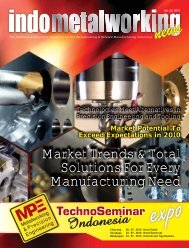
Vol. 03 / 2008<br />
news<br />
The Indonesian Quarterly Magazine for the Metalworking & Related Manufacturing Industries<br />
Indonesia Features:<br />
Jepang akan membantu proyek pengembangan<br />
manufaktur Indonesia<br />
Program hemat tahap II 25 Agustus<br />
THE FUTURE OF THE<br />
MILL TURN<br />
Picture with compliments from Yamazaki Mazak
e<br />
The Ind o n e s ian Qu a r terly Ma g a z ine for th e M e talwo rking & Re lated Ma n u fac turing Ind u s trie s<br />
The Indo n e sia n Qu a r terly Ma g a z ine for the Me tal wo r kin g & Re lated Ma n u fac t u r ing Ind u s tries<br />
The Ind o n e s ian Q u a r terly Ma g a z ine fo r th e Me tal working & Re lated Ma n u factu ring Ind u s trie s<br />
Contents<br />
Indonesia Features:<br />
Jepang akan membantu proyek pengembangan<br />
manufaktur Indonesia<br />
Program hemat tahap II 25 Agustus<br />
Indonesia Features:<br />
Vol. 03 / 2008<br />
news<br />
Jepang akan membantu proyek pengembangan<br />
manufaktur Indonesia<br />
Program hemat tahap II 25 Agustus<br />
Indonesia Features:<br />
Vol. 03 / 2008<br />
news<br />
Jepang akan membantu proyek pengembangan<br />
manufaktur Indonesia<br />
Program hemat tahap II 25 Agustus<br />
Vol. 03 / 2008<br />
news<br />
On the Cover<br />
THE FUTURE OF THE<br />
MILL TURN<br />
THE FUTURE OF THE<br />
MILL TURN<br />
THE FUTURE OF THE<br />
MILL TURN<br />
Picture with compliments from Yamazaki Mazak<br />
Picture with compliments from Yamazaki Mazak<br />
Picture with compliments from Yamazaki Mazak<br />
The DMU 50<br />
Compact but powerful - from 3 axes to 5 axe<br />
The Milling Future Age<br />
A decade of Moldmaking Progress<br />
Tangential Milling of Mold & Dies<br />
Industry & Technology<br />
Cam Nesting Tricks for Waterjet Cutting<br />
Super Turbo-X champion Laser Cutting<br />
Quick Turn Star 200<br />
VARIAXIS 500-5X II<br />
A New Star is Borne!<br />
The new<br />
BTSA 200-60BE Essential<br />
Steel plate handling with<br />
magnets comes of age<br />
Clinching the case in fastening<br />
Solidworks technology overview<br />
The Tribological Challenges of<br />
High Speed Machining<br />
Work Smart: Balancing Price<br />
and Productivity<br />
Toolong for zero stock machining<br />
Quality & Inspection<br />
Advances in defect detection<br />
08<br />
09<br />
11<br />
15<br />
17<br />
20<br />
22<br />
24<br />
26<br />
28<br />
30<br />
36<br />
38<br />
41<br />
Automation<br />
44 Successful Robotic Deburring is<br />
Really a Matter of Choices<br />
Shop Management<br />
49 The Strategy and Tactics of Hiring<br />
Indonesia Features<br />
52<br />
7 Sektor Industri dikecualikan dari ketentuan<br />
Industri didorong pakai mesin baru<br />
Jepang akan membantu proyek pengembangan<br />
manufaktur Indonesia<br />
Program hemat tahap II 25 Agustus<br />
2 Sektor Industri dapat perlakuan khusus Bea<br />
Masuk<br />
Just for the Thought<br />
55 Machine tool fi nancing - Conserve<br />
working capital<br />
Fresh from the oven<br />
57 Fueling the engine of change<br />
News Snippets<br />
59<br />
Dutacipta siapkan Rp 129 Miliar bangun baja siku<br />
Mittal garap pabrik baja terintegrasi senilai<br />
US$800 juta<br />
4<br />
indometalworking news Vol. 3 / 2008
Editorial<br />
Skill Wanted Desperately<br />
Stanley Setyaatmadja is an interesting guy as I came<br />
to know him during one of the talks he gave recently.<br />
In many ways Stanley reminded me of an old-time<br />
preacher, pounding on the pulpit, but in his case, he was not<br />
talking about spiritual matters. Instead, he’s on a patriotic<br />
crusade to urge and move our beloved country, Indonesia,<br />
forward and into the future.<br />
His fi nance driven quest is a total passion for him. People<br />
adore him and are impressed with the way he structured Adira<br />
and completely brought Adira to the future with Danamon.<br />
He’s known to be very brilliant when it comes to fi nance<br />
management.<br />
Refl ecting on his words, recently one of my best friends<br />
phoned in to ask, “Edwin, I’m debt free now, but I want to<br />
send my kid to college. Do you think I should borrow money to<br />
send him to school?”<br />
I asked, “How much money?” “About $50,000 over a fouryear<br />
period”, he replied.<br />
“What’s your son going to study,” I then asked. “Business,<br />
I suppose”, he said.<br />
After choking a bit, I asked him something like, “You’re going<br />
for a $50,000 loan, so that when your son graduates, he has<br />
the potential to earn $15,000 a year to start with? Does that<br />
make sense?”<br />
Then my friend went on about what he believes would be the<br />
expectation of the new era and the new economy.<br />
“This is still the era of SKILL,” I told him while recalling<br />
what Stanley had said. “Unless your son is going to study<br />
something that is totally unique and guarantees that he’ll<br />
make lots of money, I would send him to a lower-cost state<br />
school. In today’s world, graduates have to compete with<br />
hundreds of thousands of graduates in India and China. If you<br />
look at salary scales, people with skills, such as computer<br />
programming or engineering, do a lot better in the beginning<br />
than business graduates.”<br />
In the 8 years of my worklife, I’ve been mingled up with various<br />
walks of business people. Most of them whom I know were<br />
either billionaires already, or are well on their way to becoming<br />
so. Plus, most of them are self-made entreprenuers with only<br />
high school or less formal education.<br />
So how did they make it? Interestingly, most of them started<br />
out as skilled craftsmen or engineering hands, people who<br />
could create and produce things to be bought by others!<br />
In this issue I put an emphasis on the Japan-Indonesia<br />
technology transfer skills and posted an article on the new<br />
technology on milling. But, going back to the start line, the<br />
Right SKILL is in crucial need to uphold the existence of our<br />
business in metalworking especially.<br />
MTT 2008 is here, taking place 27-30 August, in our country.<br />
There will be many new technology introduced and many new<br />
features coming up to make our business more competitive<br />
in the global arena. Seems to me, if we want to sprout more<br />
fi nancially successful people in this country, we ought to start<br />
with grooming more skilled labour and thus, more effective<br />
trainings have to be coursed out and implemented.<br />
Hmmmmmmm. . . .something to think about.<br />
Edwin Widjaja<br />
Editor in Chief<br />
PT IndoBiz Connection<br />
Gedung Hero II 8 th fl oor<br />
Jl. Gatot Subroto Kav. 64 No. 177A Jakarta Selatan - Indonesia<br />
Telp. : +62-21-657 00 022<br />
Fax : +62-21-266 45 463<br />
Contact :<br />
Melissa Ng<br />
Edwin Widjaja<br />
sales@indo<strong>biz</strong>.<strong>biz</strong> (advertisement)<br />
editor@indo<strong>biz</strong>.<strong>biz</strong> (articles/editorial)<br />
All rights reserved. No Portion<br />
of this publication covered<br />
by the copyright herein may<br />
be reproduced in any form or<br />
means - graphic, electronic,<br />
mechanical, photocopying,<br />
recording, taping, etc -<br />
without the written consent<br />
of the publisher. Opinions<br />
expressed by contributors and<br />
advertisers are not necessarily<br />
those of the publisher and<br />
editor. All of the articles are<br />
based on the original author.<br />
6<br />
indometalworking news Vol. 3 / 2008
The DMU 50<br />
Compact but powerful – from<br />
3 axes to 5 axe<br />
The DMU 50 from DMG represents the ideal basis for entry into the<br />
innovative CNC universal milling sector, especially for the forward<br />
thinking entry-level users of 5-axis machines, with machines equipped<br />
with high-tech components and extensive options, already included in<br />
this compact machine. Highlights contributing to the increased dynamics<br />
of the DMU 50 include digital drives in all axes as well as on the main<br />
spindle with up to 14,000 rpm. Apart from the standard-equipped fi xed<br />
table, a number of optional confi gurations are available such as a manual<br />
or driven swivel rotary table with a hydraulic table clamping device. This<br />
adds two additional machining axes. State-of-the-art control technology<br />
with the DMG ERGOline® Control, a 19” TFT-screen and 3D-software<br />
ensures the fastest job processing times as well as superb precision and<br />
reliability. With the DMU 50, DMG offers the perfect, economically priced<br />
machine for entry into the world of 5-axis milling centres.<br />
Within the DMG Group, DECKEL MAHO Seebach quite recently had still<br />
been concentrating on the smaller universal machines on the milling<br />
segment. Since the 2004 launch more than 400 machines per year were<br />
sold. The DMU 50 in the new DMG design supersedes both of these<br />
models at the same time. Starting with the basic machine, the customer<br />
can choose from several equipment versions – in particular three table<br />
variants consisting of a rigid table, a manual swivel rotary table and<br />
a motor-driven hydraulically clamped swivel rotary table. Hence the<br />
DMU 50 develops the whole world of innovative milling – from 3-axis<br />
technology to 5-side complete machining.<br />
At the same time, the DMU 50 features drive powers up to 13 kW, rapid<br />
traverses up to 24 m/min, fl exible retooling and a tool magazine for up<br />
to 30 tools, enabling it to perform even highly complex tasks with high<br />
productivity and short tooling times. Both, the magazine and the tool<br />
changer are located outside the machining chamber, an arrangement<br />
that protects them from soiling and facilitates retooling during productive<br />
cycles.<br />
The modular layout of the DMU 50 is the ideal basis for the production<br />
of complex individual parts and short runs with maximum precision and<br />
surface quality. This is also ensured by the highly stable structure of the<br />
compound rest with inherently rigid, ribbed cast components combined<br />
with the machine base of cast PC.<br />
Performance, ergonomics and universality are the outstanding features<br />
of the available alternative controllers, too. Either Siemens 840D<br />
powerline, Heidenhain iTNC 530 or Heidenhain MillPlus IT – all three<br />
high performers are convincing candidates with high memory capacities,<br />
ultra fast processors and excellent user friendliness thanks to their<br />
19” the DMG ERGOline® Control TFT screens and 3D software support.<br />
Via Ethernet they also allow direct access to external networks – and<br />
therefore to DMG Netservice, too.<br />
Highlights of the DMU 50<br />
DMG ERGOline® Control, a 19” TFT-screen and 3D-software for easy visual programming<br />
Powerful motor spindle with up to 14,000 rpm (optional), 100Nm and 18.9 kW<br />
Variable table options, from fi xed to swivel rotary table with digital drives – for automated 5-axis machining<br />
High workpiece weights and maximum precision due to integrated swivel rotary table with large diameter roller bearings in both rotary axes<br />
Excellent accessibility to the work area, good chip disposal and steep slanted walls, large work area in relation to small machine size<br />
Tool magazine for setup parallel to production time, optionally for 16 or 30 tools<br />
Specifications<br />
x / y / z axis<br />
max. speed<br />
power (40 / 100% duty)<br />
torque (40% duty)<br />
max. rapid traverse x / y / z<br />
tool magazine*<br />
controllers<br />
* optional<br />
mm<br />
rpm<br />
kW<br />
Nm<br />
m/min<br />
500 / 450 / 400<br />
20 – 10,000 / 20 – 14,000*<br />
13 / 9<br />
83<br />
24<br />
16 / 30<br />
Heidenhain iTNC 530<br />
MillPlus IT<br />
Siemens 840D Powerline<br />
Captions:<br />
DMGs DMU 50 in the new DMG Design opens up a new era for tool, jig and prototype building, whether in the training centre or workshop.<br />
These CNC systems are convincing candidates with high memory capacities, fast processors and excellent user friendliness thanks to their 19” TFT screens and 3D software.<br />
The optional motor-driven hydraulically clamped swivel rotary table opens up the whole world of innovative 5-side machining.<br />
8<br />
indometalworking news Vol. 3 / 2008
Combining Milling and Turning is the answer for future..<br />
Mill-turn centers make domestic<br />
manufacturing adept to change<br />
and, with effi cient use of labor,<br />
more competitive on a global scale.<br />
Mill-turn machines—whether the<br />
industry uses “multitasking,” “multifunction,”<br />
“multiprocess” or another<br />
adjective to describe them—are the new<br />
stars of the machining universe, touted<br />
to lower costs, reduce setups and keep<br />
manufacturing stateside. What used to<br />
be handled in multiple operations can<br />
now be clamped once, machined, then<br />
taken out—complete.<br />
“Due to rapidly changing market<br />
demands, the life-cycle of merchandise<br />
in general has become shorter,” said<br />
Brian Papke, president of Mazak Corp.,<br />
at its Touch the Future event. “Because<br />
of this, today’s market strongly demands<br />
the multi-tasking concept.” In a<br />
manufacturing environment embracing<br />
lean, he said, “what is more lean than<br />
producing parts complete in a single<br />
fi xturing?”<br />
One shop owner in Guang Zhou, China<br />
“is a progressive individual—very much<br />
a disciple of ‘lean,’” says Michael J.<br />
Hillock, Marketing Director at Hardinge<br />
Asia, adding that he is interested on the<br />
future machine tool world. His concept<br />
was to “make a machine-tool small<br />
enough so he could put it on a pallet<br />
truck and push it around his shop” to<br />
whichever cell required it. Although<br />
machines aren’t there yet, they can<br />
take a growing library of parts and part<br />
families.<br />
Such high-tech machines fi ll the needs<br />
for high-growth markets in the Europe,<br />
USA and Japan, including the medical<br />
industry. “That industry is growing every<br />
year by 30 percent or more,” says Olaf<br />
Tessarzyk, CEO of INDEX Corp. “Do I<br />
see growth [for these machines] in the<br />
world.? Absolutely.”<br />
Historically, some manufacturers have<br />
viewed mill-turns as too complex. And no<br />
wonder. Finding qualifi ed labor proved<br />
hard enough, but fi nding someone to<br />
manually program a mill-turn center’s<br />
multitude of axes was, in some labor<br />
markets, not practical.<br />
But a solution, sources say, is coming<br />
from two places: intuitive technology<br />
inside the modern mill-turn, and a push<br />
for training focused not only on the<br />
fundamentals of metalworking but on<br />
the problem-solving creativity these new<br />
machines bring to the shop fl oor.<br />
RIGIDITY AND INTUITIVE CONTROL<br />
These machines are designed to “take<br />
the heat,” so to speak, of many unlike<br />
components working together. “You<br />
have beds, you have steel linear roller<br />
ways, you have steel turrets, you have<br />
unlike material within that machine, and<br />
they’re all put together to build a machine<br />
tool,” says Gayle Vollmer, director of<br />
technical resources at Okuma. “It’s all<br />
in relation to the thermal coeffi cient,<br />
the expansion of mass. Everything that<br />
is a different size is going to grow at a<br />
different rate.”<br />
Because of this, “we need to make<br />
the machine ‘thermally friendly,’” he<br />
says, meaning “we know where the<br />
thermal weak points are, and we can<br />
compensate for them with the design of<br />
the machine.”<br />
“Elements are moving all over the place,”<br />
Vollmer continues. The machine slide<br />
produces friction, which turns into heat.<br />
Cutting produces heated chips that drop<br />
in different places, all the while coolant<br />
is thrown into the mix. “You have a lot<br />
of different temperatures going on<br />
inside the machine tool, so you have a<br />
lot of different things affecting thermal<br />
stability.”<br />
Mori Seiki also sees machine-tool<br />
technologies are transforming mill-turns<br />
into “full-performance machines” in<br />
milling and turning capabilities.<br />
indometalworking news Vol. 3 / 2008 9
Most signifi cant, according to sources,<br />
is that these machines overall have<br />
become more intuitive. Collision<br />
protection has matured to the point<br />
where, in some cases, a crash can be<br />
avoided even during manual operation<br />
mode. As the control software becomes<br />
more intuitive and increasingly operatorfriendly,<br />
so does the viability of mill-turn<br />
machines in increasingly diverse shop<br />
environments.<br />
Vollmer says that offl ine programming<br />
optimization and automatic NC<br />
generation have made the technology<br />
more accessible. So today, “when you<br />
put the programming on the machine,<br />
you’re not spending a lot of time<br />
debugging and making sure certain<br />
elements clear.”<br />
Consider a part that requires upper and<br />
lower turrets to perform simultaneous<br />
roughing. That, in some cases, can be<br />
diffi cult to program, because it has two<br />
turrets coming in at the same time.<br />
AdMac system that will automatically<br />
program those turrets coming in at the<br />
same time, and synchronize everything<br />
together: the correct spindle speed, the<br />
correct feed rates.<br />
The anti-collision system analyzes the<br />
machine through real-time simulation<br />
to prevent crashing. So if the operator<br />
places an incorrect tool or sets the<br />
wrong offset, the controller will detect<br />
that and not allow the machine to go<br />
there.<br />
With the fear of collision, that simulation<br />
technology has matured to the point<br />
where “we can see every little dent or<br />
burr that will be made on the toolpath.<br />
Working together with Siemens, INDEX<br />
now offers 3D modeling of a “virtual<br />
machine” customized for a particular<br />
machine model. The end result? A<br />
simulated end part is “no longer just<br />
similar” to the end product, he says.<br />
“It’s a one-to-one copy.”<br />
FINDING PEOPLE<br />
The manufacturing program wasn’t<br />
meeting the needs of local business—<br />
particularly aerospace and medical,<br />
where new machining technologies<br />
brought a challenge: How do technical<br />
schools train future machinists on new<br />
machines without actually having one<br />
for students to use? The answer lay in<br />
the basic soft skills and critical thinking<br />
that, essentially, teaches students to<br />
learn effi ciently, work with others and<br />
take initiative.<br />
Now, in Indonesia, the Center for<br />
Manufacturing Excellence has been<br />
set up with coordination between<br />
government and Japan. Supported in<br />
part by the IMDIA, the center attempts<br />
to resurrect the fundamentals,<br />
granting students a Certifi cate in Basic<br />
Manufacturing. Specifi cally, educators<br />
hope to give students various skills in<br />
decision-making, teamwork, systems<br />
and processes, and other areas. Today’s<br />
student still needs the fundamentals.<br />
Companies need machinists who<br />
communicate their intimate knowledge<br />
of a machine to help make a better<br />
part.<br />
True, intuitive interfaces, simulation<br />
and other software advancements have<br />
opened the door to mill-turns for many<br />
shops. But without well-honed, problemsolving<br />
creativity, a manufacturer may<br />
well not take advantage of a modern<br />
machine’s fl exibility.<br />
The more we do in a machine, the more<br />
complicated it gets, and it takes more<br />
skill to run it. Consider a machinist who<br />
used to operate three machines all<br />
day. Today, he might have one multifunction<br />
machine—and put out a lot<br />
more products. On top of that, he works<br />
with software to help make the products<br />
more effi ciently, and, to prepare for part<br />
changeovers, he may perform process<br />
planning as well. Before, the shop ran<br />
as many parts as it could, because<br />
changing parts meant having three<br />
spindles down. With one multi-process<br />
machine, part change-over is fast,<br />
batch runs become shorter, inventories<br />
become lower, “and the result is more<br />
effi ciency.” The operator and setup<br />
personnel must “look at a part and ask,<br />
‘How much of this part can I do in this<br />
machine before I really have to move it<br />
again?”<br />
According to Mr. Takahashi, Chairman<br />
of IMDIA, some shops that make best<br />
use of multi-function machines may<br />
soon see consolidation of job functions.<br />
Today, a shop may have an operator, a<br />
setup person and a programmer. “To<br />
me, in the future, [the three jobs] may<br />
be done by one person,” he explains.<br />
The job description of a traditional<br />
machinist, he says, will “migrate into a<br />
setup engineer,” and that engineer “will<br />
be ideal if he can also program parts.”<br />
Such a shift would make training easier,<br />
he says. “You would only train one person<br />
instead of three.” In addition, “this will<br />
give people more job satisfaction in<br />
the long run,” he adds, explaining that<br />
while programming and seeing the<br />
part through manufacturing, the setup<br />
engineer would take ownership over<br />
that part.<br />
For a future machinist’s day-today work<br />
with these multi-function machines,<br />
the trend will be more emphasis on<br />
tool selection and programming. “To<br />
be successful with any type of millturn,<br />
shops need a skilled machinist<br />
who’s fl exible and able to perform<br />
multiple operations.” Cross training<br />
has become more important than ever.<br />
Viewing milling and turning as separate<br />
disciplines is gone.<br />
For programmers, this is their era. For<br />
people who can program, understand<br />
the machine and unleash it, this is<br />
their chance to shine. The potential is<br />
limitless for the future of Milling.<br />
10<br />
indometalworking news Vol. 3 / 2008
There has been a tremendous<br />
amount of change in the global<br />
moldmaking industry over the past<br />
10 years, and mold shops that adopt new<br />
machine tools, services and technology<br />
will enhance their capabilities for longterm<br />
success.<br />
Throughout the last 10 years, the<br />
rate of change has increased and<br />
technology has led to new possibilities<br />
in mold design and production. The<br />
most signifi cant industry changes have<br />
been in regard to production techniques,<br />
manufacturing speeds, mold size and<br />
mold complexity.<br />
moldmaking industry has been the<br />
rise of off-shoring and its associated<br />
effect on pricing. European and U.S.<br />
moldmakers are increasingly feeling the<br />
pressure of foreign competition.<br />
While U.S. moldmakers have lost<br />
a portion of less complex, lower<br />
technology, commodity work to overseas<br />
competitors, it’s not all gloom and doom.<br />
This void in commodity manufacturing<br />
has been fi lled with<br />
value-added products<br />
and services, which<br />
foreign markets<br />
struggle to provide. Moldmakers are<br />
fi nding success by taking advantage of<br />
unique or emerging industries such as<br />
medical, micro, large molds and highvalue<br />
tooling.<br />
Several niche markets have emerged.<br />
One of the most profi table is the medical<br />
market, which demands complexity,<br />
speed, and intricate mold designs on a<br />
daily basis.<br />
As the industry changes, so too must<br />
machine tools and the associated<br />
Large, complex molds and micro molds<br />
have replaced small, simple-cavity<br />
molds. Greater emphasis is being<br />
placed on production leadtimes speed,<br />
and agility. Japanese shops are turning<br />
to advanced machine tools and cutting<br />
edge manufacturing approaches to help<br />
reduce costs and meet the demanding<br />
just-in-time production schedules.<br />
It comes as a shock to no one that<br />
the driving factor of change in the<br />
indometalworking news Vol. 3 / 2008 11
manufacturing techniques. After all,<br />
what good is a hefty micromachining<br />
contract if you don’t have the appropriate<br />
tools to complete the job? “Faster” and<br />
“more complex” are terms that are<br />
thrown around a lot these days—in the<br />
same sentence as “tighter tolerances”,<br />
“fi ner surface fi nish”, “better blends<br />
and matches” and “less hand working.”<br />
Just as moldmakers change to meet<br />
the needs of their customers, suppliers<br />
have to change to meet the needs of<br />
their customers. That means innovative<br />
technology and even more innovative<br />
applications engineers.<br />
Collapsed Leadtimes,<br />
Better Results<br />
Ten years ago, it would not have<br />
been uncommon for the leadtime<br />
to manufacture a mold to be in the<br />
12 to 16 week range—three to four<br />
months. However, over the past decade<br />
signifi cant technological advancements<br />
in both machine tools technologies<br />
and manufacturing techniques have<br />
drastically reduced production times.<br />
Today, the leadtime to manufacture<br />
the same mold would be two to four<br />
weeks—often less than one month.<br />
Trial parts can be quickly molded using<br />
rapid prototype cavities created in a day<br />
or two. Now, time-to-market concerns<br />
often require production in weeks or<br />
even days, something that would have<br />
been thought unrealistic only a few<br />
years ago.<br />
In addition to demanding faster cycle<br />
times and shorter leadtimes, customers<br />
expect tighter tolerances and higher<br />
quality surface fi nishes. Typically, doing<br />
a job faster produces a lower-quality<br />
product. Unfortunately, in this industry,<br />
quality defi nes who a moldmaker is. If<br />
quality suffers, business suffers.<br />
Machine Tool Technology<br />
As a result, moldmakers are turning to<br />
the machine tool builder for products<br />
that deliver higher productivity, greater<br />
precision, better surface fi nishes, and<br />
eliminate additional time-consuming<br />
hand fi nishing work. To meet this need,<br />
machine tool builders have dramatically<br />
increased machine axis velocities<br />
and accelerations, greatly expanded<br />
spindle rpm, while tightening positioning<br />
accuracy, repeatability and geometric<br />
tolerances. Control enhancements also<br />
have facilitated high-speed machining<br />
of complex, three-dimensional mold<br />
shapes to tighter tolerances.<br />
A decade ago, 10,000 rpm was<br />
considered a fast spindle and 10 ipm<br />
federates were acceptable. Today,<br />
machines routinely incorporate 20,000,<br />
30,000 and even 40,000 rpm spindles,<br />
and feedrates of 200, 300 and 400<br />
ipm are commonplace. Combining<br />
these advanced machine tools with new<br />
manufacturing techniques—such as<br />
high-speed milling routines and tooling,<br />
hard-milling to eliminate multiple steps<br />
of machining, and high performance<br />
machining utilizing programming tricks<br />
and machine capabilities have provide<br />
the moldmaker with the necessary tools<br />
to compete and win.<br />
In the past, it was virtually impossible<br />
to get a fi nished mold directly from a<br />
machine tool. A moldmaker would fi rst<br />
machine the mold in the steel’s soft<br />
state, cutting a mold cavity that was<br />
fairly rough. After heat treating, the<br />
mold would be fi nished machined to as<br />
close to the fi nal tolerances as possible.<br />
Ten years ago, the typical tolerance<br />
that might be achieved was +/- 0.002<br />
inches. After hours of cleaning up<br />
the core and cavity by hand, the mold<br />
components would be ready for initial<br />
assembly. The two mold halves would be<br />
fi t together and additional hand working<br />
would be required to actually create the<br />
proper fi t and clearances between the<br />
working parts of the mold. Only after<br />
this labor intensive and time-consuming<br />
process was it actually ready for a test<br />
shot. Once again, after the initial parts<br />
were molded—typically, there would<br />
be additional hand-polishing required<br />
to meet part fi nish requirements and<br />
some additional fi tting work to insure<br />
proper match-lines, seams and no fl ash<br />
on the fi nished part. Not to mention the<br />
fact that the mold would often have to<br />
be machined twice—once for the initial<br />
geometries and a second time after<br />
heat-treating to harden the mold.<br />
Machining in the Hardened State<br />
Perhaps the biggest step forward to<br />
reduce the time of recent years is the<br />
ability to cut the mold in the hardened<br />
state, often eliminating the two rounds<br />
of machining required and the wait-time<br />
for heat treating. A decade ago, it was<br />
understood that hardened steels were<br />
typically to be fi nish machined, and more<br />
often than not, hand fi nished. Today’s<br />
machines1 are capable of machining<br />
materials in the 60+ Rockwell range,<br />
and have even successfully machined<br />
carbide at 80+ HRc.<br />
Given this ability, machining in the<br />
hardened state is not only possible,<br />
but preferable, because it frequently<br />
eliminates the time consuming EDM<br />
process. However, there is still a place<br />
for EDM. This is especially true for<br />
diffi cult-to-machine areas, such as deep<br />
ribs, tough radii, and very tight-tolerance<br />
features.<br />
Burning on a Ram EDM is very accurate,<br />
but it also is very slow, particularly on<br />
a complex or large mold. Having the<br />
ability to mill in the hardened state<br />
without the use of Ram EDM saves<br />
overall mold production time and aids in<br />
the timely delivery of the mold, thanks<br />
to the simplifi ed process and cutting<br />
directly to zero on the milling machine. A<br />
12<br />
indometalworking news Vol. 3 / 2008
hardened block goes into one machine<br />
and a fi nished mold comes out.<br />
By using advanced machine tools,<br />
moldmakers can eliminate additional,<br />
labor intensive, time-consuming,<br />
expensive steps and cut mold<br />
components to zero with accuracies to<br />
+/- 0.0005 inches or less in materials<br />
of 60 HRc and harder. Using machine<br />
tools that allow them to reach these<br />
tolerances and mill in the hardened state<br />
eliminates additional hand fi nishing and<br />
fi tting, provides outstanding surface<br />
fi nishes, helps shops shorten leadtimes<br />
and reduce costs dramatically, giving<br />
them a defi nite advantage relative to<br />
overseas competition.<br />
Many customers report that the primary<br />
reason they’re still successful, even<br />
after losing simple work to lowercost<br />
providers, is due to their<br />
ability to turn out high quality molds<br />
quickly. They credit their teams of<br />
innovative engineers, new processing<br />
techniques and tooling, along with the<br />
ever-advancing machine tool, which<br />
allows them to produce molds faster<br />
and without the need for re-work, as<br />
is all-too common when work is sent<br />
overseas.<br />
Areas of Growth Potential<br />
Re-Working Overseas Molds<br />
Perhaps one of the more interesting<br />
markets we’ve seen in moldmaking in<br />
recent years is applying the European<br />
or U.S or even Japanese quality to<br />
overseas molds in Asia such as China<br />
or Thailand. In other words, shops are<br />
fi nding that making poorly made molds<br />
work properly, even having to re-machine<br />
features or whole molds, is an area of<br />
growth potential.<br />
Even the<br />
simplest<br />
molds<br />
have<br />
to fi t<br />
thousands of miles away from where it’s<br />
used, the mistakes of the molder often<br />
can’t be corrected effi ciently without<br />
bringing in a local craftsman with highperformance<br />
machining abilities.<br />
Often, these orphaned and defective<br />
molds have already been heat treated,<br />
so those willing to take on this work<br />
have to fi x the mistakes in hardened<br />
steel. They need hardmilling skills and<br />
a machine capable of cutting hardened<br />
tool steel, as mentioned earlier.<br />
Re-working defective overseas molds is<br />
a new and growing sector of moldmaking<br />
with great potential for those willing to<br />
fi x the mistakes of others and invest<br />
in machinery capable of high-accuracy<br />
hardmilling.<br />
Demand for Micro<br />
Advanced manufacturing technologies<br />
have made micro components and<br />
devices commercially viable for the<br />
aerospace, automotive, electronics and<br />
biomedical industries. Mass replication<br />
of these devices requires micro molding,<br />
forming and stamping technology on an<br />
economical scale.<br />
together<br />
properly and the<br />
resulting parts must<br />
meet specifi c fi nish and tolerance<br />
requirements. When a mold is produced<br />
Micromachining certainly has its<br />
share of challenges. Cutting forces<br />
and tool pressures on cutting tools<br />
as small as 0.05 mm in diameter are<br />
signifi cantly different than those on<br />
larger applications. Machine tools<br />
designed for micro must be able to<br />
recognize and achieve submicron<br />
movement commands. Machine tool<br />
stiffness and rigidity also are extremely<br />
important here, as even the slightest<br />
distortion or defl ection will destroy the<br />
dimensional integrity of such miniature<br />
parts. Unchecked temperature<br />
change can quickly overshadow micro<br />
component tolerances. In addition, do<br />
not underestimate the challenges of<br />
measuring parts and part features in<br />
indometalworking news Vol. 3 / 2008 13
the micron range.<br />
Some shops are producing fl at parts<br />
in materials such as 420 stainless<br />
steel that require tolerances of 0.0002<br />
inches, with absolutely no variance, over<br />
as much as a 6-inch distance.<br />
Micromachining requires tremendous<br />
technology advances in tool construction<br />
and design, and usually calls for careful<br />
programming and very small tools that<br />
are hard to handle. But with the demand<br />
for miniaturization at an all-time high,<br />
those shops that have adopted the<br />
proper technology are quickly realizing<br />
the benefi ts.<br />
Large Mold Manufacturing Requires<br />
Specialized Tools<br />
Big molds require a substantial<br />
investment, which includes massive<br />
tooling that’s hard to move, heavy-duty<br />
machinery and other equipment to make<br />
the process as effi cient as possible.<br />
Modern high-performance machining is<br />
widely accepted to be a cost-effective<br />
solution for the production of small<br />
mold cavities with complex geometric<br />
surfaces. But the same demand for<br />
detail is often overlooked in selecting<br />
machinery for the production of larger<br />
molds. When dealing with large mold<br />
production more is invested in material<br />
costs and time, which increases the<br />
risk associated with scrap and re-work,<br />
placing greater emphasis on the quality<br />
of machinery used to manufacture these<br />
large tools.<br />
It’s a signifi cant challenge for<br />
moldmakers to get these operations set<br />
up to the point where they can be run<br />
effi ciently. As a result, large moldmakers<br />
are using high-end CAD/CAM systems<br />
that are capable of generating effective<br />
toolpaths. This technology, coupled<br />
with machine tools that can remove<br />
materials at faster rates unattended will<br />
greatly help large moldmakers reduce<br />
production times.<br />
Molds Are Growing in Complexity<br />
In addition to size, mold complexity<br />
is becoming a signifi cant issue in the<br />
moldmaking industry. Today, more<br />
emphasis is being put on ultra-precision,<br />
multi-cavity injection molds, specifi cally<br />
for customers in the medical, packaging<br />
and technology markets.<br />
Some complex molds can have more<br />
than 1,500 parts and require extreme<br />
levels of accuracy and precision. As<br />
precision moldmakers take on more<br />
complex work, they are spending more<br />
time planning their molds and turning to<br />
reliable machine tools with excellent cut<br />
times and accuracy that eliminates the<br />
need for hand-work so they can turn out<br />
more molds more quickly.<br />
Surface fi nish requirements can become<br />
a major issue, as some complex molds<br />
don’t allow hand-polishing in areas where<br />
a human hand can’t fi t. The machine has<br />
the job of fi nishing the part, and has to<br />
perform this task fl awlessly to allow the<br />
mold to work properly.<br />
Moldmakers are relying more on<br />
advanced machines with fast control<br />
capabilities to speed up production<br />
on complex molds. They are looking to<br />
integrate total performance packages to<br />
process long, complex mold programs,<br />
at extremely fast speeds, while achieving<br />
levels of accuracy and fi nish previously<br />
unattainable.<br />
Diversification<br />
A new, emerging trend is for mold shop<br />
owners to take a hard look at their<br />
core competencies in order to discover<br />
where those abilities can be applied in<br />
other markets. While not giving up on<br />
moldmaking, these innovative shops<br />
are applying their machining and<br />
manufacturing expertise to satisfy the<br />
demands of aerospace, medical, energy<br />
and telecommunications customers.<br />
These shops are fi nding that excess<br />
capacity can be quickly put to work in<br />
highly profi table production areas, as<br />
well as traditional moldmaking, allowing<br />
them to bid on a whole variety of new<br />
work.<br />
This strategy of diversifi cation can<br />
be an effective means of increasing<br />
business by utilizing the skills and<br />
equipment already in place to satisfy<br />
new customers.<br />
After all, the production business<br />
currently booming in Europe and U.S<br />
Continent is that of the highest precision<br />
in tough materials, which is exactly the<br />
type of work moldmakers are used to.<br />
Not limiting your shop to molds can go a<br />
long way to a better the bottom line.<br />
Change Is a Constant<br />
There has been a tremendous amount<br />
of change in the global moldmaking<br />
industry over the last 10 years. While<br />
theses changes can be attributed to<br />
increased competition from foreign<br />
markets and a myriad of technological<br />
advances, the results are easily seen<br />
in process improvements, increased<br />
quality and capabilities, and faster<br />
production speeds, which allow<br />
advanced countries moldmakers to<br />
compete like never before.<br />
More and more European or U.S.<br />
moldmakers will continue to adopt new<br />
machine tools, services and technology<br />
that help them to enhance their<br />
capabilities by manufacturing complex,<br />
large and micro molds. In doing so, they<br />
further differentiate themselves from<br />
competitors, both foreign and domestic,<br />
and that has always been the name of<br />
the game.<br />
14<br />
indometalworking news Vol. 3 / 2008
Tangential Milling<br />
of Mold & Dies<br />
In most die and mold shops, one<br />
of the biggest single chunks of<br />
machining time goes to slab milling,<br />
so speeding that operation exerts a lot<br />
of positive leverage on profi tability and<br />
competitiveness.<br />
Just consider a company’s workshop<br />
that has a very progressive die and<br />
mold shop that runs 24/6 serving the<br />
automotive and truck-body market. Over<br />
the past year, one has switched over to<br />
tangential milling for the rough and fi nish<br />
slabbing work, and raised throughput<br />
more than 40 percent. Tool life rose<br />
as well, while power consumption<br />
dropped.<br />
It does the slab milling with an<br />
assortment of Ingersoll tangential milling<br />
cutters – 4 in, 6 in, 8 in, 12 in and the<br />
new 1 in diameter cutters, the smallest<br />
tangential milling cutter available.<br />
Saving 20 Hours of Every Shoe<br />
“Every time I slab a die shoe now – and<br />
we do several of them daily – I save<br />
20 hours,” says the Machine manager.<br />
“Tool life is up as well, and power<br />
consumption is down. The power meter<br />
that used to read 95 percent of machine<br />
capacity or higher now hovers nearer 80<br />
percent. We gradually standardized on<br />
tangential milling for fl at slabbing work<br />
a couple of years ago, and since then<br />
I know we’ve already saved more than<br />
$100,000 in machining time, and I’m<br />
sure the power reduction will also help<br />
our machines last years longer.”<br />
This company’s workshop represents<br />
one of the fi rst applications of the new<br />
1 in S-MAX Micro tangential milling (TM)<br />
cutter, which brings the proven benefi ts<br />
of tangential milling to smaller work.<br />
Inserts Lie Flat for Stronger<br />
Presentation<br />
In tangential milling, the inserts are<br />
oriented differently. They lie fl at around<br />
the cutter’s pitch line rather than<br />
standing up radially, as in conventional<br />
cutters.<br />
This tangential orientation presents the<br />
insert’s strongest cross section to the<br />
main cutting force so that the inserts<br />
last longer. The result has always been<br />
much longer edge life.<br />
The tangential milling concept was<br />
introduced back in the 1960s and<br />
expanded ever since. The main original<br />
role for the tangential milling process<br />
was to improve tool life on big jobs<br />
like hogging wide-area fl ats on large<br />
indometalworking news Vol. 3 / 2008 15
the power meter pegged,” he added.<br />
The company mills the dies dry on an<br />
Okuma MCRV 2 and a G&L bridge-type<br />
machine. Ingersoll suggested the S-MAX<br />
tangential milling cutter and proposed a<br />
test against the old conventional zerorake<br />
face mills and other competitors.<br />
The trial was comprehensive, running<br />
over four weeks and including four other<br />
leading makes of face mill. All the other<br />
candidates had conventional radial<br />
insert orientations and a variety of lead<br />
angles: 30 deg, 45 deg and 90 deg.<br />
slabbing. It also cuts smoother because<br />
the tangential design fi ts more inserts<br />
into the pitch circle than is possible with<br />
conventional cutters.<br />
And they’ve notched up the removal<br />
rate still further besides. Its’ standard<br />
for rough slabbing cast iron die blocks<br />
now stands at 40 to 60 ipm and 0.400<br />
in DOC. For fi nishing, it’s now 108 ipm at<br />
0.010 in to 0.015 in DOC. Their previous<br />
standard for fi nishing was 30 ipm at<br />
0.010 in to 0.015 in DOC.<br />
automotive castings and steel parts.<br />
Now with freer cutting insert geometries<br />
and smaller cutter diameters, tangential<br />
milling is emerging as a solution for faster<br />
removal with lower cutting forces. The<br />
wider size range of cutters also makes it<br />
a good option on small slots and cavity<br />
work as well as large-area slabbing. The<br />
only ‘must’ is that the bottom of the cut<br />
be fl at. “Todays’ tangential milling may<br />
be a lot of good things to a lot more<br />
people, even on low hp machines,”<br />
claimed Ingersoll Technical Director,<br />
“but its Z-axis contouring capabilities<br />
are limited.<br />
Test Shows A Better Way<br />
The company’s conversion to tangential<br />
milling began with a suggestion, and a<br />
test, in early 2008. It was looking for a<br />
way to speed up one of their bedrock<br />
operations and eliminate too-frequent<br />
tool failures, and asked Ingersoll<br />
company for suggestions. Their main<br />
obstacle to faster milling with the old<br />
tool was tool rupture, not gradual wear.<br />
“The inserts simply broke off, leaving<br />
a stump,” said the project manager at<br />
that company. He was also concerned<br />
about and the high power consumption<br />
that could burn out a motor or stall the<br />
machines. “Sometimes the needle on<br />
All tests were run on identical cast iron<br />
material on the same Okuma and G&L<br />
machines, with the same operator. All<br />
began with the same starting conditions,<br />
and then Meyer and Upton pushed the<br />
removal rate to fi nd a new optimum.<br />
The starting point was its’ previous<br />
standard: 25 ipm feed, 0.150 in depth<br />
of cut (DOC). At the end of the test, the<br />
Ingersoll tangential cutter had optimized<br />
out at 40 ipm and 0.300 in DOC, and<br />
with 30 percent longer edge life and 10<br />
to 15 percent less power consumption.<br />
That was three times faster than its’<br />
previous norm for rough slabbing, and<br />
40 percent faster than with any other<br />
cutter in the test.<br />
Standardizing, Pushing the Limits<br />
Today the company does virtually all<br />
rough and fi nish slabbing with 4 in, 6 in,<br />
8 in or 12 in S-MAX face mills, depending<br />
on the size of the die, the width of the<br />
cut and the amount of material to be<br />
removed.<br />
The 4 in and 1 in cutters have a 90 deg<br />
lead angle for milling square corners in<br />
pockets. They are just phasing in the<br />
new 1 in S-MAX Micro cutter to speed<br />
machining of up step-down pockets and<br />
trim line cutting as well as bottom and<br />
shoulder milling in cavities. It appears<br />
at least as fast in the small spots as<br />
the larger cutters are in the wide-area<br />
Widening Role for Tangential<br />
Milling<br />
The application demonstrates how<br />
tangential milling has expanded its role.<br />
Originally the TM process was targeted<br />
as solution for improving insert life for<br />
heavy milling on high-power machines<br />
in transfer lines.<br />
On such synchronous lines, throughput<br />
at a single station is rarely an issue<br />
unless it is the slowest station. Today,<br />
the combination of tangential orientation<br />
and free-cutting insert geometries<br />
makes TM a solution of choice for<br />
smaller cuts, even on lower-power<br />
stand-alone machines and machining<br />
cells. As long as the bottom of the cut<br />
is fl at, the TM process stands a good<br />
chance of speeding up most any milling<br />
operation.<br />
16<br />
indometalworking news Vol. 3 / 2008
Programming<br />
can play a role<br />
in managing the<br />
entire process and<br />
give competitive<br />
advantage<br />
By taking part-geometry in the form<br />
of CAD fi les in and outputing NC<br />
code used to control a waterjet<br />
cutting machine, CAM nesting software<br />
automatically and effi ciently arranges<br />
the required quantities of individual<br />
parts needed for optimizing sheets or<br />
plates of stock material.<br />
A variety of specialized CAM software<br />
available today is developed<br />
independently from machine suppliers<br />
that provides a single software solution<br />
allowing companies to operate all<br />
brands of waterjet machines (and other<br />
processes), regardless of CNC controller<br />
type. Although use of material is still a<br />
core focus, nesting software now plays<br />
a central role in other areas: maximize<br />
part quality, reduce programming time<br />
indometalworking news Vol. 3 / 2008 17
and complexity, optimize manufacturing<br />
system productivity, provide detailed<br />
operator and management information.<br />
For example, consider a few of these<br />
opportunities where programmers can<br />
provide a competitive advantage:<br />
Quality. Different cut speeds deliver<br />
different edge quality when applied to a<br />
particular material and thickness. This<br />
is useful to maximize productivity and<br />
achieve the desired part quality. The<br />
width of the cut being made by the jet<br />
nozzle is called kerf. Generally speaking,<br />
the slower a jet nozzle moves across the<br />
material being cut, the wider the cut<br />
– the larger the kerf – it makes. In hard,<br />
thin material such as ½ in (12 mm)<br />
stainless steel this effect is negligible.<br />
But kerf can enlarge up to 0.005 in (0.1<br />
mm) or more in thicker material or softer<br />
material.<br />
Programmers can set the desired edge<br />
quality via the nesting program using<br />
either CAD line color to automatically<br />
set a specifi c cut speed, or by manually<br />
assigning a cut speed to the CAD fi le<br />
after it has been imported in to the<br />
nesting program. Also, the offset setting<br />
in the software is typically intended to<br />
correct for the cutting width of the jet.<br />
However, if the offset is manually set<br />
by an operator and based upon the<br />
average width of the jet, it may not fully<br />
account for any slight variations in the<br />
cutting width as the jet slows for corners<br />
or speeds up for straight cuts.<br />
or in small circles during the piercing<br />
process, known as dynamic piercing,<br />
helps avoid this problem.<br />
Ramping. To achieve optimum edge<br />
quality and part geometry, cut speed<br />
ramping is required. Programmers can<br />
vary cut speed for incremental CAD line<br />
segments, based on part geometry such<br />
as corner angle or radius size.<br />
Clamping. Effective clamping of work<br />
materials is necessary in many cases.<br />
Forces imparted from the jet and<br />
movement from water in the tank below<br />
can cause the sheet or plate to vibrate<br />
or even fl oat and move during cutting.<br />
Programmers can establish safe zones<br />
on the nest where clamps are used.<br />
These are not fi lled with parts and are<br />
avoided during cutting. Avoiding specifi c<br />
areas on the nest is also useful when<br />
cutting work material such as stone or<br />
leather, which typically contains defects.<br />
In some cases it is possible to overlay<br />
a digital picture of the work material<br />
to the nest area, making it possible to<br />
nest around defects to avoid scrap and<br />
wasted time.<br />
Collision Avoidance. Avoiding<br />
nozzle damage from tipped up parts<br />
is important. Though some machines<br />
are equipped with crash protection,<br />
this does not really treat the root of<br />
the problem. By assessing a variety of<br />
factors, nesting software can determine<br />
a certain probability of a profi le tipping<br />
up or warping on the sheet. With that<br />
knowledge, a cut path is automatically<br />
developed that moves the head around<br />
any profi les using a partial or zero headraise,<br />
or directly over profi les with a<br />
full raise depending on which is faster.<br />
Also, intelligent lead in/out locations<br />
may ensure that the head always moves<br />
away from the previously cut profi le,<br />
negating the need to create avoidance<br />
paths altogether.<br />
Reports. Communication of the<br />
job(s) relevant information between<br />
programmer, machine operator, and<br />
management is another vital key to<br />
success. Nesting software reports<br />
can assist with material selection and<br />
preparation, scheduling jobs, tending<br />
to the job during cutting, etc. A variety<br />
of reports are typically available, often<br />
incorporating images of the nest, cut<br />
sequence, production time and cost per<br />
part and per job, etc.<br />
Dynamic Piercing. Being able to<br />
pierce materials without requiring a<br />
mechanically-drilled starter or pilot hole<br />
is a strong feature of waterjets, but there<br />
are some limitations. For example, when<br />
piercing thicker material the jet has a<br />
tendency to rebound directly into itself,<br />
reducing the effective power of the jet.<br />
Using nesting software to program the<br />
cutting head to move back and forth<br />
Continued to page 40<br />
18<br />
indometalworking news Vol. 3 / 2008
A New Star<br />
is Borne!<br />
Introducing...<br />
“Why does BRUDERER place a new automatic punching press<br />
in this segment?” you may want to ask. Well, the answer<br />
is quite simple: The demands put up by the market have<br />
changed considerably and the<br />
BSTA 200-60BE is the answer to such changes. Following<br />
a thorough and precise market study and many talks with<br />
our customers all over the world, the new requirements were<br />
converted and realised not only in the machine but also in a<br />
new control and a new feed design.<br />
In those fi elds where high-precision micro parts must be<br />
stamped in large numbers, namely in the electronic, watch<br />
making and automotive industry, things have undergone<br />
enormous changes during the past 5 years. The materials<br />
to be stamped became ever thinner, the feed pitches ever<br />
shorter, the required precision ever higher, and the pricing<br />
pressure ever stronger. Furthermore, the process following<br />
the stamping process, as for instance the assembly of the<br />
components or the over-moulding of the punched parts,<br />
requires an ever higher accuracy and above all, maximum<br />
repeatability. With the BSTA 200-60BE Essential, BRUDERER<br />
is able to fulfi l these requirements perfectly.<br />
The automatic punching press<br />
The press force in the target segments is not the primary<br />
problem. Most applications require press forces of a few<br />
tons. Therefore, the new machine type was designed for a<br />
press force of 20 tons. For BRUDERER this means that the<br />
machine may actually be operated with these 20 tons without<br />
affecting the high precision and machine & tool life.<br />
One new feature is the use of a drive system using 2 connecting<br />
rods in a machine with 20 tons punching force. This brings<br />
along an essentially higher stability and precision in the<br />
punching process. In addition, the unique ram adjustment<br />
by BRUDERER is realised in the new BSTA 200-60BE - this<br />
unit is able to automatically compensate any offset in the<br />
20<br />
indometalworking news Vol. 3 / 2008
BDC area during the punching process. Hence the ram BDC<br />
can be kept in minimal tolerances, regardless of speed and<br />
temperature changes!<br />
The punching tools which became longer and longer despite<br />
the ever shorter feed intervals caused us to defi ne a tool<br />
loading area of 600mm. Alternatively, the automatic punching<br />
press will also be available with 700mm tool loading area<br />
starting from the middle of 2007.<br />
The standard model of the automatic punching press is<br />
designed as fi xed stroke machine. This mainly fulfi ls the<br />
demands of the Asian markets where most of the machines<br />
are used for the production of electronic components.<br />
However, our sales program also includes the adjustable<br />
stroke as an option in order to also satisfy other markets or<br />
needs. With the smallest fi xed stroke of 8mm, the machine<br />
may be operated at a speed of 2,000 spm.<br />
The feed units:<br />
The roller feed unit BBV 180 is a new development as well.<br />
Like the other roller feeds by BRUDERER, it is mechanically<br />
driven via a cardan shaft. The new BBV 180 allows for the<br />
quick and simple replacement of the rollers which improves<br />
the fl exibility and productivity. If so required by the process,<br />
also a gripper feed unit may be used. We offer a specially<br />
designed gripper feeder, which has been developed as a<br />
joint effort between BRUDERER and SANKYO of Japan. The<br />
special gripper feeder is moved between the guide supports.<br />
This means it is much closer to the stamping die which helps<br />
to reduce or even eliminate the strip guiding problems which<br />
occur when using thin and sensitive material.<br />
The control:<br />
On the basis of the proven B-control,<br />
we have designed and developed a<br />
new machine and process control.<br />
The so-called „B-Essential“ fulfi ls all<br />
requirements of a state-of-the-art<br />
control and is very easy to operate. Via<br />
the touch screen, the operator may enter<br />
all relevant information quickly and in a<br />
perfectly structured way or may even update and optimize<br />
these data during the punching process. The operation is<br />
aimed to focus more on the capabilities of the operator than<br />
to the automation. Back to the roots of the machine – and only<br />
that is needed in the process - is our motto. The hardware is<br />
confi gured in a way that all rotating elements, as for instance<br />
ventilator and hard disc, were eliminated. Concerning the<br />
hardware, the main focus was placed on reliability and long<br />
life. The concept also resulted in a considerable reduction of<br />
the control cabinet size.<br />
Summary:<br />
The new BSTA 200-60BE und 70BE Essential offer the<br />
perfect choice for the production of small but high-precision<br />
punched parts. Through a design and construction precisely<br />
tailored to the needs of target group and marked by costconscious<br />
considerations as essential factor throughout the<br />
entire development phase, a machine was built which will<br />
boost the competitiveness of our customers. In addition, we<br />
attached great importance to easy handling and maximum<br />
productivity through the choice of the appropriate control<br />
components and feed units.<br />
www.bruderer-presses.com<br />
indometalworking news Vol. 3 / 2008 21
Steel Plate handling with magnets comes of age<br />
Commercial shipbuilding, oil<br />
and petrochemicals and steel<br />
fabrication industry is currently<br />
experiencing its biggest and most<br />
enduring boom in history. Since 2005,<br />
shipyards worldwide received orders<br />
worth a total of $400 billion. More<br />
than 7,000 new ships have been<br />
launched since 2005 and within the<br />
next few years. Average prices for<br />
new ships have jumped by more than<br />
half in the last four years. This boom<br />
is not unexpectedly driving the steel<br />
fabrication and plate cutting market<br />
towards greater effi ciencies including<br />
improved cutting technologies, better<br />
welding equipment and consumables<br />
and last but not the least, steel plate<br />
material handling equipment.<br />
Since the advent of magnetic material<br />
handling technology, magnets have<br />
been used to lift and move most types<br />
of steel raw materials. By replacing<br />
traditional slings, chains and clamps,<br />
lifting magnets have improved overall<br />
productivity by allowing fewer operators<br />
to lift and place steel materials<br />
for further processing. Magnetic<br />
technology has also seen vast<br />
improvements over time with newer<br />
and more powerful magnets comprised<br />
of rare earth materials and with a<br />
combination of mechanical actuation<br />
and/or electrical impulses.<br />
It can be recalled that magnets always<br />
have a north and south pole across<br />
which magnetic fi eld energy or ‘fl ux’<br />
fl ows and ferrous components placed<br />
in this fi eld develop a momentary<br />
opposing polarity which attracts the<br />
opposite poles of the magnets.<br />
Magnetic clamping and lifting devices<br />
made by mechanical actuation of raw<br />
magnets are often called permanent<br />
magnets. These operate by actual<br />
physical movement of the raw magnets<br />
inside a carrier which determines the<br />
ON or OFF state. The advantage offered<br />
by these are portability and ease of<br />
use. However, these are limited only<br />
by capacity as the actual physical<br />
movement to orient the magnetic poles<br />
becomes too much for larger contact<br />
area of workpieces.<br />
To overcome the physical limitation of<br />
Figure 1 Figure 2<br />
permanent magnets, Electromagnets<br />
became the default choice of<br />
clamping and lifting devices for<br />
larger workpieces. These magnets<br />
are comprised of an electrical coil<br />
wrapped around a soft iron core<br />
and use the principle of magnetism<br />
which is generated by an electrical<br />
direct current passing through the<br />
coil. The iron core helps to direct the<br />
magnetic fi eld in a certain direction<br />
and the electromagnets are effective<br />
and ‘energised’ only as long as the<br />
supply current remains on. Although<br />
electromagnets provide the fl exibility<br />
of magnetic fi eld control through<br />
power supply variation, these systems<br />
can also be quite unsafe especially if<br />
power supply is unpredictable. That is<br />
Figure 3 Figure 4<br />
why electromagnets often need to be<br />
accompanied by battery backup and<br />
uninterruptible power supplies.<br />
Electropermanent magnets have<br />
gradually become popular as clamping<br />
devices due to its inherent advantages<br />
of not relying on continuous supply<br />
of electricity and for its additional<br />
ability to vary the magnetic fi eld depth.<br />
These use a combination of two types<br />
of permanent magnets one of which<br />
is electrically switchable (grey, right)<br />
with a coil winding (blue) around that<br />
and another permanently magnetized<br />
(yellow) in a certain way. When a direct<br />
current is momentarily passed through<br />
the coil, the reversible permanent<br />
magnet is magnetized in a certain<br />
pattern driving the fl ux fi eld outward.<br />
The Electropermanent magnet is<br />
switched ON (fi gure 1) and remains<br />
in that state until a ‘demagnetising<br />
pulse’ of direct current is passed in<br />
the opposite direction. When that<br />
happens, the reversible magnet is<br />
magnetized in the opposite direction<br />
and the fl ux fi eld dissipates within<br />
the construction (fi gure 2) and the<br />
Electropermanent magnet is switched<br />
OFF. The biggest advantage of the<br />
Electropermanent magnets are their<br />
ability to remain in an energized state<br />
even if the incoming power supply<br />
is switched OFF due to a electrical<br />
failure or power supply outage. These<br />
are therefore deemed to be safe as<br />
workpieces will not be discharged<br />
should there be an accidental power<br />
trip.<br />
There are quite a number of pole<br />
face designs in clamping magnets<br />
implementing the Electropermanent<br />
technology but the most popular one is<br />
probably the square pole type. These<br />
magnet clamping devices, depending<br />
on how they are oriented, can be<br />
effectively used for clamping (fi gure 3)<br />
or lifting (fi gure 4).<br />
For single large steel plate of 12 to<br />
16 Meters and thicknesses from<br />
5mm onwards weighing upto 25<br />
tons, the Electropermanent magnet<br />
technology presents a great alternative<br />
to traditional jaw clamps for handling<br />
the plates without deformation. The<br />
magnetic fi eld depth is adequate to<br />
penetrate and saturate the steel plate<br />
and these are lifted either horizontally<br />
or vertically onto the work area. For<br />
loading and unloading of single steel<br />
plates onto plasma, fl ame and steel<br />
plate cutting and blasting machines,<br />
a complete system comprising several<br />
electropermanent magnet modules<br />
suspended from spreader beams<br />
are increasingly being employed for<br />
large plate handling by shipyards<br />
and steel fabricators rushing to meet<br />
order deadlines and cashing in on the<br />
current boom.<br />
22<br />
indometalworking news Vol. 3 / 2008
Mazak: Super Turbo-X champion Laser Cutting<br />
1 st time in Indonesia! Mazak’s new generation Super Turbo-X<br />
48 Champion laser processing machine for sheetmetal with<br />
proven constant-beam-length delivery offer unsurpassed<br />
cutting performance, anywhere on the table. The most unique<br />
feature of this machine is its non-stop cutting capability of<br />
different materials and material thickness without changing<br />
the focal lens or nozzle. Mazak’s new quick-change torch<br />
assembly also provides fast, easy access to the focal lens.<br />
This stand-alone laser machine can also be integrated after<br />
initial installation with a wide variety of unmanned operation,<br />
material handling equipment to enhance productivity.<br />
Quick Turn Star 200<br />
Quick Turn Star 200 is a compact CNC 8” chucker designed to meet production<br />
requirements of a wide variety of work pieces.<br />
It’s SUPERIORITY in specifi cation and performance ensures exceptional productivity<br />
of stable and high-accuracy machining. Though too compact as it looks, it is very<br />
TOUGH to endure heavy cutting conditions. In order to attain ACCURATE and stable<br />
machining, a wide range of advance technologies such as integral spindle/motor was<br />
incorporated in its extensive machine design. A compact and user-friendly machine<br />
which minimizes operator’s task even for extended period of time that will provide you<br />
value for money RELIABLE for your production requirements!<br />
11kW (15HP) 8”-chucker. 12D turret, tool shank 25x25mm, boring bar 40mm tooling<br />
capacity. Standard work of 200xL100mm with a max turning diameter of 280mm.<br />
30/33 m/s traverse speed for X/Z axis. F0i base EIA/ISO NC. And 1220mm minimum<br />
machine length.<br />
VARIAXIS 500-5X II<br />
A new dimension for higher productivity.<br />
The ability to machine a workpiece’s top surface, side surfaces and any<br />
surface in between makes it possible to completely machine a workpiece<br />
in a single set up. Additionally, complex contours can be processed and<br />
considerable reduction of in-process time and production cost thanks<br />
to 5-axis simultaneously controlled machining. For higher effi ciency,<br />
the operator can setup the next workpiece during the machining of the<br />
current workpiece.<br />
The VARIAXIS II series are equipped with a high-rigidity, high-speed spindle<br />
and utilizes a wide variety of advanced technologies in order to provide<br />
exceptional productivity.<br />
The “DONE-IN-ONE” concept incorporates all machining processes from raw material input through fi nal machining – in just<br />
one machine. It provides the ability to reduce production lead time, improve machining accuracy, reduces fl oor space and<br />
initial cost, lower operating expenses, reduce operator requirements and to improve the work environment. As a result the<br />
concept not only streamlines production, it also improves overall management.<br />
24<br />
indometalworking news Vol. 3 / 2008
CLINCHING THE CASE IN FASTENING By Leon M. Attarian<br />
When designers evaluate methods<br />
for fastening and joining in an<br />
assembly, the application will<br />
rule. Along the way, inherent challenges<br />
and outcomes among the various available<br />
technologies ultimately may disqualify<br />
one or another approach. For example,<br />
in applications involving thin-metal<br />
attachment, adhesives have been known<br />
to fail (especially when heat or vibration<br />
are present); welding can be “messy” and<br />
time-consuming; and sheet-metal screws<br />
or loose hardware can fall short in the areas of reusability and holding<br />
power. Self-clinching fasteners take the higher road by providing<br />
permanent, reliable, and reusable load-bearing threads in thin metal<br />
sheets. Upon installation (during fabrication), they become integral<br />
parts of an assembly; will not loosen or fall out; and never have to be<br />
handled again. This type of hardware further allows for component<br />
removal and re-attachment whenever needed for access or service; can<br />
dramatically reduce or eliminate the amount of attachment hardware<br />
(such as loose washers, lock washers, and nuts); and usually requires<br />
only mating hardware to complete fi nal component attachment. Fewer<br />
parts promote lighter designs and less hardware in an assembly yields<br />
more savings in production time and costs.<br />
FORM AND FUNCTION<br />
Dozens of types and thousands of variations of self-clinching fasteners<br />
have been developed over the years, including free-running, selflocking,<br />
fl oating, and blind-hole types meeting unifi ed, ISO, and MIL<br />
standards. (All of our standard product line is RoHS compliant, too.)<br />
Self-clinching hardware typically is made from steel, stainless steel, or<br />
aluminum and many types can install permanently in metal sheets as<br />
thin as .020”/0.51mm. Traditional product families include nuts, studs,<br />
spacers and standoffs, access hardware, and cable tie mounts and<br />
hooks. Specialized types have been engineered to satisfy applicationspecifi<br />
c purposes.<br />
Brief profiles:<br />
• Nuts. Standard types are designed with load-bearing thread<br />
strengths greater than mild steel screws. Variations focus on nut size,<br />
locking-thread properties, and special alloy materials for manufacture.<br />
All clinching during installation occurs on the fastener side of the sheet;<br />
the reverse side remains fl ush and smooth. A mating screw fi nishes<br />
the job.<br />
• Studs. These externally threaded self-clinching fasteners are<br />
generally selected for applications where a component must be<br />
positioned in advance of fi nal attachment. Flush-head studs are<br />
standard, but variations can specifi cally satisfy high torque, thin<br />
sheet, or electrical applications. Studs without threads can double as<br />
permanently mounted guide pins or pivots.<br />
• Spacers and Standoffs. Designed primarily to stack or space<br />
components, the most common types include thru-threaded and blindthreaded<br />
versions. All install with their heads fl ush within the host sheet<br />
and, using blind-threaded types, outer panel surfaces of an assembly<br />
are smooth and closed. Variations include standoffs with concealed<br />
heads and others that allow printed circuit boards to snap into place for<br />
easier board assembly and removal.<br />
• Access Hardware. Self-clinching panel fastener assemblies<br />
incorporate captive screws to keep loose parts to a minimum and<br />
eliminate risks associated with hardware that can loosen, fall out, and<br />
damage internal components. They ideally will be specifi ed to attach<br />
metal panels or other thin material components in applications where<br />
subsequent access will be necessary.<br />
• Cable Tie Mounts and Hooks. These provide permanent attachment<br />
points for mounting wires and cables to electronic chassis or<br />
enclosures without screws or adhesives. Ties slide easily through<br />
the “eye” in mounts and hooks can be used to attach, remove, and<br />
return tie-bundled wires at their mounting points when components<br />
need to be accessed for service or when wires or cables must be<br />
replaced. The hardware remains permanently installed and secure<br />
at designed locations. Regardless of type, self-clinching fasteners<br />
install permanently in thin ductile metal sheets by pressing them into<br />
place in a properly sized drilled or punched hole and applying suffi cient<br />
squeezing force. This process causes displaced sheet material to cold<br />
fl ow into a specially designed annular recess in the shank or pilot of the<br />
fastener, permanently locking the fastener in place. A serrated clinching<br />
ring, knurl, ribs, or hex head prevents the fastener from rotating in the<br />
metal when tightening torque is applied to mating hardware. Fasteners<br />
can be installed in small quantities with a tool as simple as an arbor<br />
press or in high volumes using automated or in-die equipment. Perhaps<br />
the most important factor to consider when specifying for success is<br />
the relative hardness of fastener and host metal sheet. The fastener<br />
must always be harder than the sheet in which it is installed. This is<br />
how the “softer” displaced sheet material is able to cold fl ow into the<br />
fastener’s recess to lock the fastener securely in place.<br />
TIPS FOR DESIGNERS<br />
When specifying self-clinching fasteners, designers may want to<br />
keep these basic guidelines top-of-mind:<br />
• Accommodate the specifi c application. Every self-clinching fastener<br />
type can bring an advantage to the table. If an assembly requires<br />
PCBs or components to be stacked, standoffs deliver the goods. If<br />
UL requirements for subsequent access to an assembly represent an<br />
issue, designers can turn to panel fasteners as solutions.<br />
• Evaluate secondary benefi ts. Many self-clinching fasteners<br />
demonstrate unique performance capabilities -- often more than one<br />
-- which can be applied to maximize their effectiveness and contribute<br />
meaningfully to end-product assembly. Case in point: A self-clinching<br />
fastener that mates two panels at a right angle offers an added benefi t<br />
by enhancing EMI/RFI shielding (since the need for cutouts in the<br />
middle of panels is eliminated).<br />
• Ensure integrity of fastener design. The production of quality selfclinching<br />
fasteners begins with good engineering research, design,<br />
development, and testing. Precision is necessary in all facets of<br />
fastener production. Dimensional accuracy and consistency are crucial<br />
and, if these are lacking the result will be rejected panels, chassis, or<br />
boards upon fastener installation. Even minute size variations among<br />
parts can cause automated equipment to jam, increasing downtime<br />
and production time. So-called “equivalents” rarely, if ever, rise to the<br />
occasion and to the demands.<br />
• Factor “installed cost” into selection. If fasteners are timeconsuming<br />
to install, fail upon installation and need to be replaced,<br />
necessitate additional hardware, or are diffi cult to feed into the<br />
established production process, associated costs will rise.<br />
Self-clinching fastening technology has made signifi cant strides<br />
and can constitute ideal mechanical fastening solutions, but every<br />
application will be governed by distinct parameters and requirements.<br />
Partnering at the start of the design process with an experienced<br />
hardware manufacturer can maximize all opportunities.<br />
Leon M. Attarian is Director of Marketing for PennEngineering®, 5190 Old Easton<br />
Road, Danboro, PA 18916-1000 USA. Phones: 800-237-4736<br />
(toll-free in the U.S.) and 215-766-8853; Fax: 215-766-0143.<br />
Email: lattarian@pemnet.com Web site: www.pemnet.com<br />
For all enquiries in Asia please contact us at: E-mail: singapore@pemnet.com<br />
Tel: 65-67450660 (Mr Vincent Yeo – Senior Sales and Marketing Manager)<br />
(Mr Charlie Ho – QA & Engineering Manager)<br />
Fax: 65-67452400<br />
Refers also to advertisement page 27<br />
26<br />
indometalworking news Vol. 3 / 2008
SolidWorks Technology Overview<br />
SolidWorks Corporation delivers<br />
computer-aided design (CAD) products<br />
that help designers cut development<br />
time, increase accuracy, weave<br />
more creativity into their designs,<br />
and bring better products to market<br />
faster than ever before. SolidWorks ®<br />
software allows engineers to work<br />
in 3D or 2D and helps companies<br />
become more successful by designing<br />
more innovative products for their<br />
customers. The company offers<br />
SolidWorks software as a standalone<br />
product or as the foundation of two<br />
3D CAD application suites, along with<br />
a variety of tools for analysis, product<br />
data management (PDM), design<br />
communication and collaboration, CAD<br />
productivity, specialty design, and 3D<br />
online catalogs.<br />
3D Mechanical Design<br />
Applications<br />
SolidWorks ® Office Professional<br />
SolidWorks Offi ce Professional is a<br />
3D CAD product suite that elevates<br />
designers’ creativity and productivity<br />
by marrying ease of use with advanced<br />
2D and 3D design capabilities. It helps<br />
companies accelerate product time<br />
to market by allowing engineers to<br />
complete more design work in less<br />
time. The SolidWorks Intelligent Feature<br />
Technology (SWIFT) is the fi rst CAD<br />
tool to automatically fi nd and fi x 3D<br />
CAD’s toughest challenges, enabling<br />
users to focus on design innovation,<br />
not on how to maximize the software.<br />
The software combines: SolidWorks<br />
CAD software, design communication<br />
tools that enhance collaboration,<br />
CAD productivity tools that reduce<br />
the number of steps designers need<br />
to take, and the PDMWorks ® line of<br />
easy-to-set-up-and-use product data<br />
management (PDM) tools that allows<br />
SolidWorks engineering workgroups<br />
and large geographically dispersed<br />
teams to manage all of the design data<br />
they produce.<br />
SolidWorks Office Premium<br />
SolidWorks Offi ce Premium provides<br />
a suite of product development tools<br />
that combines all of the mechanical<br />
design, design verifi cation, data<br />
management, and communication tools<br />
that engineering teams need in one<br />
product. SolidWorks Offi ce Premium<br />
includes all of the capabilities of<br />
SolidWorks Offi ce Professional as well<br />
as routing and analysis tools, including<br />
SolidWorks Routing, COSMOSWorks ®<br />
Designer, and COSMOSMotionTM<br />
SolidWorks Education Edition<br />
SolidWorks Education Edition delivers<br />
the same design functionality and<br />
ease of use as the commercial<br />
version of SolidWorks, but is specially<br />
confi gured and packaged for today’s<br />
engineering and industrial design<br />
students. It provides ease of use,<br />
power, and innovations that can help<br />
middle school, high school, technical<br />
vocational school, and college<br />
students master the fundamentals of<br />
engineering design and prepare them<br />
for successful careers.<br />
Design Validation Tools<br />
COSMOSWorks – an easy-to-use<br />
design validation tool that shows<br />
engineers how their designs will behave<br />
as physical objects.<br />
COSMOSMotion – a virtual prototyping<br />
tool that provides motion simulation<br />
capabilities to ensure designs work<br />
before they are built.<br />
COSMOSFloWorks TM – a tool that<br />
simplifi es fl uid-fl ow simulation and<br />
thermal analysis so designers can<br />
conduct tests on virtual prototypes,<br />
shortening time to market, and<br />
reducing resource requirements.<br />
COSMOSWorks Designer – a design<br />
validation tool that caters to designers<br />
and engineers who are not specialists<br />
in analysis.<br />
Product Data<br />
Management Tools<br />
PDMWorks Workgroup – a PDM tool<br />
that allows SolidWorks users operating<br />
in teams of 10 members or less to<br />
work on designs concurrently. With<br />
PDMWorks Workgroup, designers can<br />
search, revise, and vault CAD data<br />
while maintaining an accurate design<br />
history.<br />
PDMWorks Enterprise – an enterpriseclass<br />
PDM product that supports<br />
large, geographically dispersed teams<br />
of engineers, designers, sales and<br />
marketing executives, and others<br />
working in product development.<br />
PDMWorks Enterprise allows global<br />
manufacturers to automate workfl ow,<br />
streamline approvals, ensure version<br />
control, and secure the high volumes of<br />
design data they generate.<br />
Design Communication and<br />
Collaboration Tools<br />
eDrawings ® Professional – the fi rst<br />
e-mail-enabled communication tool for<br />
reviewing 2D and 3D product design<br />
data across the extended product<br />
development team. eDrawings generates<br />
accurate representations of 2D and 3D<br />
product designs that anyone can view,<br />
mark up, and measure, without having to<br />
purchase their own markup tools.<br />
3D Instant Website – a single-click,<br />
Web-publishing tool that lets designers<br />
share 3D models with customers, coworkers,<br />
and suppliers. Designers can<br />
instantly create password-protected Web<br />
sites that enable visitors to view, rotate,<br />
zoom, and pan 3D models and provide<br />
comments.<br />
PhotoWorks – a rendering tool that<br />
allows designers to create photorealistic<br />
images from 3D CAD models and<br />
include them in their presentations and<br />
proposals.<br />
3DVIA Composer – an authoring tool<br />
for creating images and 3D animations<br />
for technical publications, interactive<br />
product documentation, and marketing<br />
presentations. Typical applications<br />
include assembly instructions, customer<br />
service procedures, marketing materials,<br />
user manuals, fi eld service repair<br />
manuals, training materials, and Webbased<br />
catalogues.<br />
SolidWorks Animator – an animation<br />
tool that helps designers communicate<br />
their concepts more effectively by<br />
creating animations from SolidWorks<br />
parts and assemblies.<br />
XchangeWorks – a free data<br />
translation plug-in for AutoCAD® and<br />
Mechanical Desktop® users.<br />
DWGgateway – a free data translation<br />
tool that enables any AutoCAD software<br />
user to open and edit any DWG fi le,<br />
regardless of the version of AutoCAD it<br />
was made in.<br />
SolidWorks Viewer – a free plug-in for<br />
viewing SolidWorks parts, assemblies,<br />
and drawings.<br />
28<br />
indometalworking news Vol. 3 / 2008
There is still no universal<br />
agreement on how to define<br />
this competitive technique.<br />
There is definite agreement<br />
on how it can increase<br />
production speed, reduce<br />
costs and improve surface<br />
finish.<br />
In today’s competitive manufacturing<br />
environment, end-users of<br />
metalworking fl uids seek to maximize<br />
their productivity by manufacturing<br />
metal parts ever faster. One approach<br />
being taken is to utilize high-speed,<br />
high-feed machining.<br />
High-speed machining (HSM) was<br />
originally developed by German inventor<br />
Dr. Carl Salmon in the 1920s. He<br />
determined that for a specifi c workpiece<br />
metal, the heat generated at the<br />
interface between the cutting tool and<br />
the workpiece would peak at a certain<br />
critical spindle speed. This critical<br />
cutting speed is different for each metal<br />
alloy being machined. Salmon also<br />
determined that on either side of this<br />
peak there was a specifi c spindle speed<br />
range at which the cutting tool could not<br />
remove metal.<br />
Research on HSM was picked up by<br />
Vaughn at Lockheed Aircraft in 1959.<br />
Additional research in the 1980s and<br />
1990s, particularly in the aerospace<br />
industry, showed that HSM could, in a<br />
practical fashion, provide benefi ts as<br />
compared to conventional machining.<br />
Faster metal removal can be realized<br />
with a combination of lower machining<br />
forces and reduced power exerted by<br />
the machine tool.<br />
WHAT IS HSM?<br />
The answer to defi ning HSM would fi rst<br />
appear to be relatively straightforward.<br />
STLE (Society of Tribologists and<br />
Lubrication Engineers) member Gary<br />
Rodak of Machining Effi ciencies, Inc.<br />
(Gregory, MI) says, “There are several<br />
defi nitions of HSM, but the most<br />
common is based upon the rpm of the<br />
machine tool spindle. Some machinists<br />
consider 8,000 rpm to be the starting<br />
point for HSM, but with current machine<br />
capability anything over the 15,000<br />
rpm should be considered high speed.<br />
Operating above that spindle speed<br />
requires special attention to details<br />
such as spindle balance, machine setup,<br />
coolant application, tool paths and wear<br />
patterns.”<br />
Dr. Yung Shin, a professor of mechanical<br />
engineering at Purdue University,<br />
believes the spindle speed that<br />
designates high speed is dependent<br />
on the workpiece material. “There is<br />
no universal defi nition of HSM,” he<br />
remarks. “For metals such as aluminum<br />
and cast iron, HSM can occur at surface<br />
speeds of 2,500 fpm. In contrast, such<br />
high speeds cannot be attained with<br />
titanium. HSM of titanium can occur at<br />
speeds of 400 fpm or slightly higher.”<br />
Dr. David Dilley of D3 Vibrations Inc.<br />
(Royal Oak, MI) looks at HSM from a<br />
frequency perspective. He says, “Every<br />
tool/holder/machine combination has<br />
a characteristic dominant, natural<br />
frequency. HSM can be defi ned as the<br />
point where the tooth passing frequency<br />
of the cutting tool approaches the<br />
dominant natural frequency.” The tooth<br />
passing frequency is defi ned as:<br />
Tooth passing frequency (Hz) =rpm/60 x<br />
number of teeth<br />
This defi nition means the shape and<br />
size of the cutting tool also plays a<br />
signifi cant factor in determining if HSM<br />
can be attained in a specifi c operation.<br />
Dilley explains, “A cutting tool with eight<br />
teeth might approach the machine tool’s<br />
dominant frequency, while a tool with two<br />
teeth might not. The selection of rpm,<br />
number of teeth and depth of cut (DOC)<br />
are the most important parameters for<br />
machine tool vibrations. Cutting tools<br />
that are longer in length have lower<br />
Figure 1. Chatter wear shown on the cutting tool can<br />
signifi cantly reduce operating life and even cause failure.<br />
30<br />
indometalworking news Vol. 3 / 2008
natural frequencies, thus reaching high<br />
speed at a lower rpm. For example, a<br />
long line boring operation can be in a<br />
HSM environment at a cutting speed as<br />
low as 150 rpm.”<br />
Dilley indicates that this defi nition of<br />
HSM differs from others, as most refer<br />
to high speed spindles that relate to the<br />
DN number of the spindle bearing. He<br />
states, “HSM often takes place even at<br />
low DN numbers.” STLE member Tom<br />
McClure, vice president of TechSolve Inc.<br />
(Cincinnati, OH), also believes that HSM<br />
has many defi nitions. He adds, “The<br />
key concept is the need to manipulate<br />
speed, feed and DOC to increase metal<br />
removal rates while lowering cutting<br />
forces.”<br />
THE NEED FOR SPEED<br />
Suffi cient work has been done on HSM<br />
to show it provides several benefi ts.<br />
Rodak says, “End-users can realize<br />
faster cycle times and better fi nish on<br />
the metal parts. In fact, cycle times<br />
for specifi c machining operations can<br />
be reduced by as much as a third. The<br />
fi nish improves part quality due to less<br />
residual stress remaining in the part<br />
surface. A better quality fi nish also<br />
has a benefi cial impact on subsequent<br />
assembly and coating processes.”<br />
Shin points to three unique advantages<br />
end-users can have in utilizing HSM. He<br />
says, “HSM generates a much higher<br />
level of metal removal. The end-user<br />
igure 2. Stability Diagram Theory. The chatter-free<br />
white pockets present in the high performance region<br />
are areas where machining can be optimized and<br />
productivity increased.<br />
can increase the depth of cut during<br />
machining. Less heat is conducted<br />
into the workpiece in HSM, which can<br />
lead to less thermal distortion, reduce<br />
the forces needed and also reduce the<br />
surface roughness. Finally, less heat<br />
into the workpiece also reduces the<br />
level of residual stress.”<br />
CHATTER AUDIO ANALYSIS<br />
One of the biggest problems encountered<br />
in increasing spindle speeds is the<br />
onset of chatter. Dilley says, “Machinery<br />
systems can encounter free vibration,<br />
forced vibration and self-excited<br />
(chatter) vibration during use.”<br />
Free vibration and forced vibration are<br />
typically less destructive compared<br />
to chatter. Dilley explains, “Chatter<br />
occurs when the depth of cut and<br />
specifi c cutting energy required during<br />
a specifi c machining operation exceeds<br />
the dynamic stiffness of the cutting tool<br />
or workpiece.” Chatter creates large<br />
cutting forces that can accelerate tool<br />
wear and even cause tool failure, as<br />
shown in Figure 1.<br />
Chatter can negatively impact the<br />
workpiece quality and the machine<br />
tool integrity. The surface fi nish can<br />
be adversely affected to the point of<br />
rejection, and the operating life of<br />
machine components can be reduced.<br />
The challenge is fi nding a method to<br />
eliminate the chattering problem while<br />
maintaining throughput or cycle time.<br />
Dilley indicated that work done by Tlusty<br />
and others in the 1950s showed that<br />
there was a relationship between the<br />
DOC in a machining operation and the<br />
spindle speed.1, 2<br />
Unfortunately, machine tool technology<br />
was not adequate enough to take<br />
advantage of this relationship until the<br />
late 1980s. At that point, the aerospace<br />
industry was able to use spindle speeds<br />
up to 20,000 rpm but had trouble making<br />
metal parts any faster due to chattering<br />
until they began to utilize a “Stability<br />
Diagram.” Such a diagram for a specifi c<br />
tool/holder/machine combination is<br />
illustrated in Figure 2.<br />
Dilley maintains that no two machining<br />
setups are identical, so a given tool<br />
will perform differently in a different<br />
toolholder, and a given tool/holder<br />
combination will perform differently in<br />
Machine A vs. Machine B.<br />
However, once a given tool/holder/<br />
machine is optimized, the same<br />
parameters can continue to be used<br />
with consistent setup, as many users<br />
have been doing for the past three to fi ve<br />
years. Dilley breaks the stability diagram<br />
into fi ve regions. He explains, “The highperformance<br />
region occurs when the<br />
spindle speed is suffi ciently high that<br />
the DOC can be increased into the wide<br />
open (white) chatter-free pockets. This<br />
region is tool/holder/machine specifi c,<br />
as it may start as low as 100 rpm or<br />
as high as 15,000 rpm. The optimal<br />
conditions for machining vibration are<br />
often found in this region.”<br />
The Figure 2 diagram shows the<br />
conventional machining zone is always<br />
chatter free, which seems perfect.<br />
However, this area may not be productive<br />
for some tools, as this zone may again<br />
start at a higher rpm due to the tool/<br />
holder/machine and workpiece.<br />
The “poor man” region begins when the<br />
spindle speed increases to the point<br />
where tool/workpiece rubbing reduces<br />
and chatter is capable of developing.<br />
This is the region where most machinists<br />
reduce the rpm and increase the feed<br />
and run. Dilley states, “I, unfortunately,<br />
see many processes running in this<br />
region that could easily be moved into<br />
the high-performance region.”<br />
The Blim1 and Blim2 regions are chatterindometalworking<br />
news Vol. 3 / 2008 31
free at any rpm because the DOC is<br />
below the Blim line, which is determined<br />
by the dynamic stiffness of the system,<br />
workpiece material, number of teeth and<br />
Radial DOC (for milling). Blim1 is directly<br />
below the Poor Man Region, but as the<br />
spindle speed increases, the machining<br />
process moves into the Blim2 industry’s<br />
defi nition of HSM, where tools are run at<br />
high speeds, high feeds and low DOC.<br />
Unfortunately, productivity in mainly<br />
roughing and semi-fi nishing operations<br />
can suffer because the end-user is<br />
underutilizing the cutting and machine<br />
tools.<br />
To be more productive, Dilley maintains<br />
that the DOC must be increased and<br />
the spindle speed adjusted until the<br />
metal removal rate is maximized in the<br />
high-performance region. “The optimal<br />
parameters are diffi cult to fi nd without<br />
the proper equipment and software,” he<br />
says. “You can come close, but the trial<br />
and error method takes considerable<br />
time, and many users are only at 25<br />
percent of their possible maximum<br />
metal removal rate (mrr). Without<br />
technology, machinists and engineers<br />
do not know when to stop, as they<br />
always question if they have found the<br />
optimal parameters.”<br />
Dilley indicates that a systematic<br />
procedure can be done on each<br />
individual machining system to<br />
determine the sweet spot. This process<br />
uses one of two techniques. The<br />
fi rst is more detailed and develops a<br />
stability diagram using an instrumented<br />
hammer and an accelerometer. The<br />
second utilizes the stability diagram<br />
theory by using audio analysis with a<br />
microphone.2 An example is shown in<br />
Figure 3 for a 2-fl uted cutting tool.<br />
The points determined by audio analysis<br />
on the chatter frequency vs. spindle<br />
speed plot (lower curve) utilized the<br />
theory to locate the chatter-free cutting<br />
zone in the upper curve. A test coupon<br />
in the third diagram (Figure 3) correlates<br />
the specifi c points to their respective<br />
depths of cut.<br />
Dilley explains, “The fi rst position<br />
reached in the evaluation is point (a)<br />
which has a spindle speed of 30,000<br />
rpm and a depth of cut of 0.5 mm.<br />
Chatter was detected, so the process<br />
called for the rpm to be reduced to just<br />
over 25,000 rpm at the same depth of<br />
cut. After moving to point (b), no chatter<br />
was found, so the next step was to<br />
increase the depth of cut to determine<br />
if a higher productivity can be achieved<br />
without chatter. Unfortunately, chatter<br />
was seen at point (c) which had a depth<br />
of cut of one mm. This prompted a<br />
further reduction of the spindle speed<br />
to point (d). No chatter was observed<br />
and the depth of cut was increased to<br />
point (e).”<br />
Further attempts in this case to increase<br />
the depth of cut [points (f), (g) and (h)]<br />
proved to be unsuccessful because<br />
a two mm cut by the tool is above any<br />
stable machining pockets. Dilley states,<br />
“The net result of this analysis is that<br />
the metal-removal rate at point (e) is<br />
140 percent better than point (a).”<br />
Dilley, in conjunction with Manufacturing<br />
Laboratories, continues to research<br />
using audio analysis to better understand<br />
how to optimize HSM processes for<br />
specifi c machine tool, cutting tool and<br />
workpiece combinations.<br />
OTHER VARIABLES<br />
Overcoming chattering is a major<br />
challenge in HSM, but not the only<br />
parameter that must be considered.<br />
Rodak says, “The setup used in HSM is<br />
very important to ensuring the operation<br />
is done successfully. A chatter wear<br />
pattern on the cutting tool shows up<br />
early, is very distinctive, and is usually<br />
the fi rst destructive wear pattern<br />
Figure 3. High Performance Harmonizer Method. Audio<br />
analysis technique can be used to determine the sweet<br />
spot of each individual machining system. The curves<br />
generated on the botttom chart are used to develop the<br />
chatter-free zones shown in the top chart.<br />
that would-be high-speed machinists<br />
encounter. It is very different from a<br />
diffusion or high temperature wear<br />
pattern, which are encountered when<br />
the machine setup is correct.”<br />
He continues, “High surface or contact<br />
speeds naturally increase cutting edge<br />
temperatures, which decreases tool<br />
life. The metalworking fl uid should be<br />
delivered through the cutting tool to<br />
ensure it reaches the cutting zone.<br />
With metal removal taking place at a<br />
much faster rate than conventional<br />
machining, small particulate fi ltration of<br />
the metalworking fl uid becomes more<br />
critical in order to extend its operating<br />
life.”<br />
McClure sees machining as a system<br />
encompassing the various elements<br />
shown in Figure 4. He says, “In a similar<br />
fashion to conventional machining,<br />
six key parameters (machine tool,<br />
machining parameters, machining<br />
accessories, cutting tool, work material<br />
and the metalworking fl uid) must be<br />
evaluated as a complete system.<br />
This procedure enables machining<br />
32<br />
indometalworking news Vol. 3 / 2008
Figure 4. Machining System. Six parameters must<br />
be evaluated as a complete system to optimize the<br />
machining process.<br />
to take place in the most productive<br />
fashion possible.”<br />
HSM has not been applied successfully<br />
to all types of machining operations and<br />
metal alloys. Shin says, “The applications<br />
best suited for use in HSM are milling,<br />
drilling and turning – in that order.” The<br />
limit on developing methodology for<br />
HSM of aluminum and cast iron has<br />
been reached, according to Shin. But<br />
he believes there is plenty of room for<br />
improving work with hardened steel and<br />
titanium alloys.<br />
Shin has set up a particular machine<br />
tool that has a 30,000 rpm spindle and<br />
used it to study HSM, modeling of highspeed<br />
spindles, control of high-speed<br />
machining processes and studies<br />
looking to monitor and predict chatter.<br />
MWF CHALLENGES<br />
HSM presents some unique challenges<br />
for the metalworking fl uid. STLE member<br />
Robert Evans, senior scientist for Quaker<br />
Chemical Corp. (Conshohocken, PA),<br />
says, “An important consideration with<br />
HSM over conventional machining lies in<br />
the increased rate of metal removal and<br />
the subsequent diffi culties associated<br />
with greater heat formation and the<br />
increasing demands for rapid removal<br />
of chips from the cutting area.”<br />
Evans continues, “Minimizing<br />
temperature increases in the workpiece<br />
is of particular importance with softer<br />
metals such as aluminum alloys, which<br />
have relatively high coeffi cients of<br />
thermal expansion. Heat formation at<br />
the point of cut, if not controlled and<br />
minimized, can easily lead to loss of<br />
dimension control of the machined<br />
part. Minimizing heat formation also<br />
is important in the HSM of other light<br />
and ductile metals such as titanium<br />
(Ti-6Al-4V), which undergoes a sizeable<br />
loss in strength properties as the metal<br />
temperatures increases above 800 deg<br />
F, thus making machining extremely<br />
diffi cult. The ability of the metalworking<br />
fl uid to lubricate and cool under such<br />
conditions is critical.”<br />
Rodak adds, “Small particulate level<br />
fi ltration of the metalworking fl uid<br />
is often suboptimized and must be<br />
bolstered. The metalworking fl uid must<br />
stand up to this type of fi ltration and<br />
also reject the buildup of tramp oil.<br />
Leakage of hydraulic, spindle and way<br />
oils into the fl uid can lead to a change<br />
in the lubrication in the cutting zone,<br />
affecting cutting conditions and tooling<br />
performance. HSM coolants should<br />
be fi ltered to two micron particles and<br />
tramp oils held to a maximum of 1<br />
percent.”<br />
Foam is a very important consideration<br />
because the metalworking fl uid is<br />
subjected to conditions very favorable<br />
for its formation. Evans says, “The<br />
higher speeds lead to more shearing<br />
of the coolant and, as a consequence,<br />
the greater potential for generation<br />
of foam. The ultimate goal for fl uids in<br />
HSM operations is to have a functional<br />
composition with low inherent foam<br />
tendencies and, thus, have little or no<br />
dependency on the use of antifoam<br />
additives. If they are used, however, they<br />
should provide effective and extended<br />
antifoam properties to the coolant.”<br />
STLE member Mary Taylor, technical<br />
service director for Ultra Additives,<br />
LLC (Bloomfi eld, NJ), says, “Higher<br />
fl ow rates, fl uid velocity and pressure<br />
involved in HSM, combined with<br />
increased part movement and heat,<br />
facilitates the incorporation of air into<br />
the metalworking fl uid and, as a result,<br />
produces foam. The detergency of the<br />
coolant can act to stabilize the foam.”<br />
Taylor contends that a variety of foam<br />
diameters can be formed. She explains,<br />
“Smaller bubbles (microfoam) tend to<br />
be produced preferentially as compared<br />
to large bubbles at higher machining<br />
speeds. The mechanism of defoaming<br />
is due to the process of microfoam<br />
coalescing or unifying from a small<br />
single bubble into larger ones, which<br />
support and increase the transport line<br />
or buoyancy of the air bubbles out of the<br />
system.”<br />
Both Evans and Taylor agree that proper<br />
selection of a defoamer-added tankside<br />
may be needed to address foam<br />
problems. Taylor adds, “The engineering<br />
of the machining system is important to<br />
allow for adequate space for the foam<br />
to dissipate and settle.” Higher levels<br />
of mist can be formed during HSM<br />
For the top plate of a portable stereo, this Haas VM-3<br />
machines NAK 55 mold steel, 40 HRc using a 6 mm<br />
carbide ball endmill at 12,000 rpm @120 ipm<br />
(3 m/min).<br />
indometalworking news Vol. 3 / 2008 33
operations. Adequate ventilation and<br />
machine enclosures are probably the<br />
best way to control mist levels.<br />
USER PERSPECTIVE<br />
Protomatic Inc. (Dexter, MI) carries out<br />
custom manufacturing of prototype parts<br />
for use in a large number of applications.<br />
Doug Wetzel, vice president and general<br />
manager, says, “HSM is an integral part<br />
of our approach in providing service to<br />
our customers. We use HSM because it<br />
is much more effi cient than conventional<br />
machining and we can produce superior<br />
parts.”<br />
Wetzel believes HSM can reduce<br />
vibration and lead to an increase in tool<br />
life and improved fi nish. He says, “We<br />
machine many different metal alloys<br />
(including steel, titanium and plastic)<br />
for a large variety of applications. It is<br />
very diffi cult to shift gears without being<br />
able to use a systematic, diagnostic<br />
approach in machining. Our customers<br />
demand tighter parts tolerances, which<br />
puts the pressure on us.”<br />
Protomatic uses the vibrational analysis<br />
described earlier to optimize machining<br />
parameters. They conduct two basic<br />
metal-removal operations. Wetzel says,<br />
“Approximately 70 percent of the work<br />
we do is milling with the remaining<br />
operation being turning. Over 50 percent<br />
of the parts we make are turned and<br />
then milled.”<br />
From a metalworking fl uid standpoint,<br />
the biggest issue Protomatic faces is<br />
mist, especially when the parts are<br />
warm. Foam can also be an issue,<br />
according to Wetzel. Protomatic uses<br />
a water-based synthetic fl uid for 90<br />
percent of its operations. Wetzel says,<br />
“The metalworking fl uid is selected<br />
based on need. In some cases, we<br />
can conduct HSM without any coolant.<br />
This is particularly useful in machining<br />
plastic parts for medical applications.<br />
We cannot risk coolant contamination<br />
of parts in these cases.”<br />
CASE STUDIES<br />
Dilley discussed a problem occurring<br />
at a machine shop that was machining<br />
a pocket in an aluminum component.<br />
The company tested many tools and<br />
toolholders over months with minimal<br />
success, which they attributed to the<br />
length of the 0.25 in end mill (10:1 length:<br />
diameter). Audio analysis improved this<br />
company’s process by 90 sec per part<br />
for a production schedule of 300 parts<br />
per month (see Table 1). This represents<br />
a 7.5 hr reduction in machine time per<br />
month, or 90 hrs per year.<br />
The machine shop later eliminated the<br />
fi nish pass because the surface fi nish<br />
improved so dramatically after the<br />
process was optimized. An additional<br />
reduction of 20 sec was realized in<br />
the cycle time. The machine shop also<br />
stopped chipping tools, which reduced<br />
tooling costs.<br />
A second case study involved machining<br />
a steel part using a Makino V55 CNC<br />
machine. The operation used a 19.05<br />
mm, 4-fl ute solid carbide end mill. This<br />
machine tool can operate at a maximum<br />
spindle speed of 20,000 rpm. McClure<br />
says, “Machining at 20,000 rpm could<br />
only be done at a DOC of 1 mm prior to<br />
chattering. Reducing the spindle speed<br />
to 17,300 rpm led to an increase in the<br />
DOC to 5 mm.” The metal-removal rate<br />
increased signifi cantly, from 152 cm3/<br />
min to 659 cm3/min. As a result, the<br />
Table 1. Audio Analysis on End Mill Machining Process<br />
time needed to machine the part was<br />
cut by 17 minutes.<br />
Additional progress can be made in<br />
the future to further improve upon<br />
the HSM process. McClure says, “The<br />
cutting tools and metalworking fl uids<br />
must be updated to the extent of the<br />
machine tools in order to be able to<br />
machine at faster speeds. On a scale<br />
of 1 to 10 (where 1 represents a very<br />
rudimentary understanding of HSM and<br />
10 represents optimal utilization of the<br />
technique), the metalworking industry is<br />
now between a 6 and 7. We still do not<br />
have the skill set to better utilize HSM.”<br />
Rodak suggests a holistic approach to<br />
HSM, which includes applying worldclass<br />
techniques to the elements of<br />
good machining. He says, “Unknowingly<br />
applying suboptimized practices in any<br />
of these elements virtually assures<br />
the user of problems within the HSM<br />
environment.”<br />
Dilley adds, “The challenge in HSM is<br />
to impart a change in philosophy for<br />
running the technique. Most users<br />
do not know the capabilities of their<br />
machine tools and often underutilize<br />
them. Another hurdle is the lack of<br />
training, and much of the existing<br />
knowledge base is disappearing. If<br />
carried out properly, high-performance<br />
machining can enable an end-user to<br />
attain a 300 to 500 percent productivity<br />
improvement.”<br />
References<br />
1. Tobias, S. and Fishwick, W. (1958),<br />
“The Chatter of Lathe Tools Under<br />
Orthogonal Cutting Conditions,”<br />
ASME Trans. 80, pp. 1079–1088.<br />
2. Delio, T., Smith, S. and Tlusty, J.<br />
(1992), “Use of Audio Signals in<br />
Chatter Detection and Control,”<br />
ASME J. Eng. Ind. 114, pp. 486–492.<br />
3. Canter, N. (2006), “Metalworking<br />
Fluid Mist: Strategies for Minimizing<br />
Exposure,” Tribology and Lubrication<br />
Technology, 61 (3), pp. 36–44.<br />
34<br />
indometalworking news Vol. 3 / 2008
Work Smart: Balancing Price<br />
and Productivity<br />
Cutting tools are<br />
unique in their<br />
effect, as relatively<br />
small investments<br />
can result in<br />
tremendous cost<br />
reductions<br />
Today’s metalworking player faces<br />
a constant barrage of challenges<br />
from customers. Demands for<br />
shorter turnaround times, reduced<br />
prices and increased precision can<br />
often overwhelm a shop’s resources.<br />
In this environment, it is not surprising<br />
that many manufacturers resort to a<br />
reactive philosophy, pursuing change<br />
only when directly called upon to do<br />
so by requirements of a customer or<br />
application. Unfortunately, this approach<br />
will usually result in missing out on<br />
potential benefi ts of new technology,<br />
some of which can have tremendous<br />
effects on productivity and profi tability.<br />
In the area of cutting tools, processes<br />
can almost be perpetually improved<br />
due to the rapid development of<br />
innovative tool designs and new<br />
insert technologies. By taking a more<br />
proactive approach to discovering and<br />
implementing these solutions, shops<br />
can increase their competitive standing<br />
in the global market.<br />
From machine tools to materials to cutting<br />
processes, many factors infl uence the<br />
total cost of producing a part. Cutting<br />
tools, however, are unique in their effect,<br />
as relatively small investments can<br />
result in tremendous cost reductions.<br />
This is due to the fact that cutting<br />
tools make up a small percentage of<br />
the total cost, but can greatly increase<br />
productivity. To understand the role of<br />
productivity on total cost, one must look<br />
at the economics of manufacturing.<br />
Manufacturing Economics<br />
Every part produced has both fi xed and<br />
variable costs. Fixed costs include the<br />
money spent on machinery, labor and<br />
overhead items—such as buildings,<br />
administration and utilities. Cutting<br />
tools and workpiece materials make up<br />
the variable portion of total part cost.<br />
In the vast majority of applications,<br />
fi xed costs far outweigh variable costs.<br />
Increasing productivity results in more<br />
parts produced, reducing the amount of<br />
fi xed costs assigned to each component.<br />
Therefore, it is usually benefi cial to<br />
accept small increases in variable<br />
costs that result in greatly increased<br />
productivity. Oftentimes, metalworking<br />
manufacturers will base cutting tool<br />
decisions off of price, opting for the<br />
cheapest available tools and inserts.<br />
Because the least expensive option<br />
typically yields lower productivity, the<br />
cost per part is likely to be higher than<br />
it should be. On average, cutting tools<br />
make up just 3 percent of a part’s total<br />
cost, while workpiece materials account<br />
for 17 percent. A whopping 80 percent<br />
falls into the fi xed cost category.<br />
Along the same lines, many purchase<br />
decisions are made on tool life. The<br />
problem with this line of thinking is<br />
that, on its own, longer tool life simply<br />
translates into a price reduction on<br />
tooling. In other words, a 50 percent<br />
increase in tool life is really just a 33<br />
percent reduction in tooling cost.<br />
36<br />
indometalworking news Vol. 3 / 2008
On the other hand, optimizing tooling on<br />
a job will usually increase productivity<br />
by 20 percent. Because a greater<br />
amount of parts can be produced in the<br />
same amount of time, the fi xed costs<br />
are spread across a greater quantity<br />
of parts. Even if the optimal tooling is<br />
50 percent more expensive than the<br />
alternative, a 20 percent productivity<br />
boost will reduce total cost per part by<br />
nearly 15 percent. The savings attained<br />
through increase productivity are clear.<br />
The Benefits of Partnerships<br />
Knowing that productivity increases can<br />
substantially cut costs, the challenge<br />
becomes fi nding the best way to<br />
achieve productivity gains. Fortunately<br />
for metalworking manufacturers<br />
today, tooling companies offer an<br />
unprecedented level of assistance.<br />
Many even have programs dedicated to<br />
helping their customers select the best<br />
tooling for specifi c applications.<br />
When looking for such a partnership,<br />
there are two key areas to be considered.<br />
1. Metalworking manufacturers,<br />
including mold maker should verify<br />
the expertise of a cutting tool<br />
supplier. It can quickly be determined<br />
if a representative of the company<br />
is truly an expert by asking detailed<br />
questions about the materials and<br />
machining processes applicable to<br />
a part. Also verify that the company<br />
will be easy to contact and readily<br />
available to help with any challenges<br />
that arise.<br />
2.<br />
If confi dent that a cutting tool supplier<br />
will bring value to a partnership, a<br />
manufacturer should examine the<br />
details of that company’s relevant<br />
programs. Is the process invasive<br />
and how will it affect production?<br />
Will representatives from the cutting<br />
tool company be working directly<br />
with machine operators to ensure a<br />
smooth transition to new processes<br />
or tools? What types of documented<br />
results or reports will be provided<br />
on test cuts and newly implemented<br />
tools? All of these issues are worth<br />
inquiring about, as they play a vital<br />
role in making the partnership a<br />
success<br />
Summary<br />
Once a working partnership with a<br />
knowledgeable cutting tool manufacturer<br />
has been established, the path has<br />
been cleared for dramatic productivity<br />
improvements. Keeping in mind that<br />
sometimes the more expensive solution<br />
results in the least amount of costs,<br />
a manufacturer can help to ensure<br />
continued competitiveness in the global<br />
market. By thinking smart and working<br />
smart, today’s mold manufacturer can<br />
earn smart as well.<br />
indometalworking news Vol. 3 / 2008 37
TOOLING FOR ZERO<br />
STOCK MACHINING<br />
Machining to net shape relies on<br />
proper end mill selection<br />
Zero stock machining (ZSM)—<br />
also referred to as net shape<br />
or negative stock machining—<br />
is the practice of producing mold<br />
components without leaving extra<br />
stock. When applied effectively, ZSM<br />
provides several important benefi ts for<br />
moldmakers: time-consuming EDM and<br />
manual operations—such as polishing,<br />
fi tting, spotting and fi nishing—can be<br />
eliminated and assembly and the overall<br />
moldmaking process time can be greatly<br />
reduced. ZSM requires that several<br />
elements—specifi cally the machine tool,<br />
programming and tooling—all be used in<br />
harmony to achieve the desired result.<br />
Suitable machine tools will offer high<br />
precision, fast spindle speeds (18,000+<br />
rpm) and feedrates (500+ ipm), as<br />
well as stability and rigidity. Effi cient<br />
programming software will result in more<br />
accurate and highly optimized toolpaths<br />
that minimize machine time. In fi ve-axis<br />
machining, the programming software will<br />
orient the cutting tool to the workpieces<br />
at the optimum angle of attack. If one of<br />
these elements is improperly selected<br />
or applied, the process will prove<br />
ineffective.<br />
End Mill Factor in ZSM<br />
This article will focus on one element in<br />
this effi cient moldmaking approach: end<br />
mills. Often, the importance of the cutting<br />
tool is minimized or overlooked entirely,<br />
but when viewed as the single interface<br />
between the machine / programming<br />
elements and the fi nished workpiece, the<br />
magnitude of their importance becomes<br />
clear.<br />
It is important to note that ZSM is not<br />
a milling technique, but rather the<br />
application of well established milling<br />
techniques (HSC and hard milling) in<br />
conjunction with an overall approach<br />
to moldmaking. ZSM constitutes a<br />
departure from the traditional methods,<br />
which requires a change in mindset as<br />
much as change in technology. One such<br />
change is to recognize the importance of<br />
the cutting tool.<br />
This discussion will also include cooling /<br />
lubrication and coating technology, which<br />
are integral to cutting tool performance.<br />
Effective High-Speed Cutting<br />
From the cutting tool perspective highspeed<br />
cutting is the foundation of ZSM.<br />
HSC is the process of machining materials<br />
at high cutting speeds (fi ve to 10 times<br />
faster than conventional machining),<br />
and highly accelerated and precise rapid<br />
movements. HSC utilizes spindle speed<br />
to take relatively light depths-of-cut<br />
at accelerated feedrates to effi ciently<br />
remove material and can be defi ned as<br />
machining at a cutting speed, which is<br />
fast enough to create a level of friction<br />
(released as heat) that the material in<br />
the shearing zone (the exact point where<br />
chips are separated from the workpiece)<br />
becomes molten. The heat resistant<br />
characteristics of carbide, combined with<br />
optimized fl ute geometry and small chip<br />
size facilitate rapid chip evacuation that<br />
keeps the area immediately surrounding<br />
the shearing zone relatively cool.<br />
Due to the high spindle speeds necessary<br />
to achieve HSC, cutting tools must posses<br />
inherently good balance characteristics.<br />
For example, straight plane shanks<br />
rather than Weldon style fl ats. Relative<br />
to fi nishing operations, tools should<br />
have an even number of fl utes to provide<br />
smoother and more even cutting.<br />
Most importantly, end mills should<br />
include micron tolerances on the shank<br />
and cutting diameter to minimize<br />
vibrations and thereby maximize tool life<br />
(see Chart 1).<br />
Successful Hard Milling<br />
As the use of hard mold steels becomes<br />
more prevalent, effective methods of<br />
material removal must be examined.<br />
Hard milling is the machining of metals<br />
with a hardness generally accepted at or<br />
above 52 Rc that cannot be machined<br />
effi ciently with conventional HSS milling<br />
cutters.<br />
Effective hard milling requires cutting<br />
tools made from much harder materials<br />
such as carbide, cermet or CBN. Carbide<br />
is preferred as the more durable, costeffective<br />
option.<br />
The following are several important<br />
cutting tool characteristics that should<br />
be considered to achieve successful<br />
hard milling and HSC: tools comprised<br />
of micro-grain or sub micro-grain carbide<br />
materials; high-performance TiAIN<br />
coatings for optimal tool performance<br />
and tool life; application-specifi c cutting<br />
geometry. Typically, the harder the<br />
workpiece the more negative the rake<br />
angle (0 to -3 degrees) and the slower<br />
the helix angle (30 to 0 degrees).<br />
Dry Machining<br />
Dry machining is preferable for machining<br />
hardened steel. Dry machining is more<br />
Chart 1<br />
38<br />
indometalworking news Vol. 3 / 2008
economical, not only by eliminating<br />
the cost of coolant, but also the cost<br />
of coolant disposal (that can easily<br />
exceed the initial coolant cost). It is also<br />
a better ecological option not only for<br />
the environment as a whole, but also<br />
because coolants can present health<br />
hazards such as allergic reactions,<br />
respiratory irritations and poisoning.<br />
From a technical standpoint, dry<br />
machining eliminates the danger of<br />
thermal shock, which may occur when<br />
relatively cold fl uid comes in contact with<br />
the relatively hot cutting tool. This drastic<br />
temperature change can cause cracks or<br />
micro-fi ssures on the tools cutting edge,<br />
which will lead directly to premature tool<br />
wear.<br />
Dry machining can be augmented with<br />
cool air blast, which serves to keep the<br />
cutting area cool and helps facilitate chip<br />
evacuation.<br />
Carbide<br />
Carbide tools are made from composite<br />
materials consisting of a relatively<br />
soft bonding agent, cobalt (Co) and of<br />
carbides (WC, TiC, TaC, Nbc), which<br />
provide hardness. Through a sintering<br />
process, the cobalt material is liquefi ed<br />
under extreme heat while the carbide,<br />
with a much higher melting point,<br />
remains solid. Once cooled, the result is<br />
a matrix of the cobalt bonding agent and<br />
the brittle carbide particles into a solid<br />
body.<br />
The end mill’s composition is an important<br />
consideration when evaluating end mills<br />
for ZSM. Carbides are available with<br />
various grain structures including nano,<br />
sub-micro, micro, fi ne, medium, coarse<br />
and extra coarse grain. Preferred tools<br />
for modern machining are made from<br />
micro or sub-micro grain carbides.<br />
Through various compositions of cobalt<br />
and carbides, different carbides and<br />
grain sizes, a multitude of hardness and<br />
toughness properties can be achieved.<br />
The proper balance between hardness<br />
and brittleness must always be obtained<br />
in carbide tools. As hardness increases,<br />
carbide becomes more brittle. When<br />
evaluating tools for hard milling, using<br />
harder carbides makes sense. For HSC<br />
in mild steel, a less hard, more resilient<br />
carbide will provide optimum tool life.<br />
Coatings<br />
PVD (physical vapor deposition) coatings<br />
are recommended for tools used for<br />
hard milling, HSC, and therefore the<br />
ZSM process. In a typical PVD process,<br />
electrodes made form titanium and<br />
aluminum are introduced into a<br />
vacuum chamber. These electrodes are<br />
bombarded by an electrical current, or<br />
arc, which vaporizes the electrodes and<br />
release charged electrons. Nitrogen<br />
gas is pumped into the vacuum under<br />
high heat and forms a plasma of gas<br />
and electrons that is attracted to, and<br />
deposited onto, the carbide as a hard,<br />
thin fi lm of TiAlN, for example.<br />
These coatings can be applied in a single<br />
layer, in multi layers or in alternating<br />
layers of different coatings, for example<br />
TiAlN and TiN (see Figure 1).<br />
Coatings play an important role relative<br />
to productivity and tool life, ultimately<br />
affecting the cost-effectiveness of<br />
the moldmaking process. In general,<br />
coatings decrease tool wear due to<br />
added resistance to friction and heat.<br />
A coatings lubricity (measured as a<br />
coeffi cient of friction) helps prevent cold<br />
welding and minimizes cutting forces.<br />
In turn, production costs are decreased<br />
due to longer tool life, higher cutting<br />
speeds and improved surface quality of<br />
workpieces.<br />
In some cases coatings can prove<br />
detrimental. For example, a relatively<br />
thick coating can have a negative<br />
Figure 1<br />
infl uence on surface quality and the<br />
sharpness of the cutting edge. Also,<br />
while multi-layer coatings can reduce the<br />
spread of cracks caused by heat friction<br />
or thermal shock, it is possible in the PVD<br />
process for electrons to clump together<br />
and form droplets within the layers. These<br />
droplets increase the surface roughness<br />
of the coating, which can have negative<br />
infl uences on chip fl ow.<br />
To combat this problem, manufacturers<br />
of quality end mills will perform a surface<br />
treatment within the fl utes, similar to<br />
polishing, which will substantially improve<br />
the roughness of coating.<br />
Also benefi cial are edge preparation<br />
treatments, which are performed prior<br />
to coating. The cutting edge is honed to<br />
minimize or remove the microscopic grind<br />
lines left by the manufacturing process.<br />
The resulting smoother surface provides<br />
a better base for coating adhesion and<br />
less opportunity for cold welding and / or<br />
material build-up on the cutting edge.<br />
Conclusion<br />
Moldmakers using ZSM need to evaluate<br />
cutting tools as carefully as they would the<br />
machine tool and programming elements.<br />
It is important to evaluate different<br />
cutters (often possible through vendor<br />
test programs) in order to determine the<br />
best tool for the application.<br />
End mills cannot be effectively<br />
evaluated based on price alone. As<br />
cutting tool technology progresses,<br />
additional features—such as edge<br />
prep, sophisticated geometries, stateof-the-art<br />
coatings and task-specifi c<br />
carbides—will add cost to a cutting tool,<br />
but the additional cost can be easily<br />
offset by the value added in tool life and<br />
performance.<br />
indometalworking news Vol. 3 / 2008 39
TRICKS OF THE TRADE<br />
From page 18<br />
Here are some tricks of the waterjet<br />
trade that operators and programmers<br />
alike should fi nd useful:<br />
• Utilizing the fl exibility of nesting<br />
software to create different ‘machine’<br />
settings in conjunction with ‘tech tables’<br />
allows programmers to quickly generate<br />
tailor made NC code depending on the<br />
desired requirements from different<br />
material types and thicknesses. For<br />
example, when cutting expensive<br />
material such as titanium, programmers<br />
can maximize material yield by using<br />
common line cutting to get the biggest<br />
bang for the buck. This requires more<br />
attention from the programmer and<br />
operator, but the yield benefi t is worth<br />
the extra manpower expense. Similarly<br />
when cutting thick material, cut quality<br />
is greatly improved by ramping into<br />
corners and, whereas using ramping on<br />
thin material may not be necessary and<br />
would increase overall production time.<br />
• When use of tabs is undesirable due<br />
to a requirement for good surface/edge<br />
quality, using toothpicks inserted into<br />
the cut path allows parts to be fi rmly<br />
held in place without falling through the<br />
cutting table.<br />
• Cutting material on top of good smooth<br />
plywood or other substrate minimizes<br />
the effect of backsplash against the<br />
underside of the material being cut due<br />
to the jet being defl ected back off the<br />
grates/slats.<br />
• Adding a plate around the front and<br />
side of the cutting table, then cutting it<br />
parallel with the machine axis, allows the<br />
operator to quickly set up sheets that are<br />
square with the travel of the machine<br />
without needing to double check the<br />
set-up and verify the alignment.<br />
• Using a crop cut in the nest allows<br />
When cutting expensive material such as titanium, programmers can maximize material yield by using common line cutting to<br />
get the biggest bang for the buck. When cutting thick material, cut quality is greatly improved by ramping into corners, whereas<br />
using ramping on thin material may not be necessary and would increase overall production time.<br />
programmers to create defi ned crop<br />
cuts, save remnants and index the<br />
sheet against the previously made<br />
‘straight’ edge at the front of the tank.<br />
This allows operators to cut sheets that<br />
are longer than the table is ordinarily<br />
capable of cutting. This maximizes yield<br />
and eliminates further operations such<br />
as shearing metal and extra loading/<br />
unloading of sheets. Indexing is quick<br />
and easy and minimizes operator fatigue<br />
and confusion, especially when reports<br />
are issued from the nesting program to<br />
graphically defi ne the process.<br />
• If the machine has a programmable Z<br />
axis, the full-raise feature can be utilized<br />
quickly and easily to avoid clamps and<br />
weights that are on the table when<br />
traversing.<br />
• Nozzle crashes are often costly and<br />
stop production due to the damage it<br />
can cause to the cutting head, as well<br />
as the chance of moving the material<br />
partway through a cut and thereby<br />
scrapping some or all of the parts.<br />
Using ‘zones’ to avoid clamps and other<br />
obstacles reduces these risks.<br />
40<br />
indometalworking news Vol. 3 / 2008
ADVANCES IN DEFECT<br />
DETECTION<br />
Here are the examples.<br />
The remarkable progress in inspection technology is<br />
having a profound impact on quality improvement.<br />
LASER WELD INSPECTION FOR SAFETY CRITICAL WELDS<br />
Automotive OEMs and suppliers, along<br />
with any other manufacturers that<br />
require Six Sigma production from<br />
their robotic welding cells, can benefi t<br />
signifi cantly from automated laser<br />
weld inspection. In conjunction with<br />
their world-leading robotic arc welding<br />
solutions, Motoman, USA offers laser<br />
inspection systems that automate<br />
checking of safety-critical welds.<br />
To provide automated weld inspection,<br />
the laser camera scans the weld profi le<br />
for visible discontinuities, such as voids,<br />
convexity, undersize and/or undercut<br />
conditions. The laser sensor is fl exible,<br />
and the user can set accept, warn and<br />
reject limits on discontinuities. Output<br />
from the sensor can be used to separate<br />
nonconforming parts from production.<br />
For Six Sigma production, the camera<br />
supplements arc monitoring by verifying<br />
that welds “look good” and are in the<br />
proper location. The laser camera<br />
provides quantifi able inspection results<br />
24/7/365. Nonconforming parts are<br />
separated from production, reducing the<br />
need to use third-party containment.<br />
Using laser weld inspection as part of<br />
the manufacturing process keeps poor<br />
quality or missing welds from being<br />
covered with additional brackets or other<br />
components. Laser cameras can also<br />
be used to inspect the fi nal weldment<br />
to detect nonconforming parts prior to<br />
assembly operations.<br />
5-AXIS CMM INSPECTION OFFERS REVOLUTIONARY THROUGHPUT<br />
Renscan5 ultra-high-speed scanning<br />
technology delivers tremendous<br />
throughput gains in coordinate<br />
measuring machine (CMM) inspection of<br />
critical and complex parts. Early adopters<br />
report 680 percent improvement on<br />
automotive cylinders heads and 922<br />
percent faster processing of jet engine<br />
blisks.<br />
Renscan5, from Renishaw Inc., meets<br />
industry needs for reduced WIP, greater<br />
process control, and ever tighter<br />
tolerances by delivering 10X and more<br />
data points. The breakthrough system<br />
combines a dynamic, infi nite positioning<br />
REVO measurement head with 5-axis<br />
machine control and a fi rst-ever lasercorrected<br />
probe to measure at speeds<br />
up to 500 mm/sec vs. conventional<br />
CMM scanning at 5-15 mm/sec.<br />
This fi ve-axis system virtually eliminates<br />
the measurement errors normally<br />
associated with existing three-axis<br />
scanning systems by allowing the smaller<br />
measuring head, a 3D measuring device<br />
in its own right, to perform most of the<br />
motion during inspection routines.<br />
This minimizes dynamic errors caused<br />
in acceleration/deceleration of the<br />
larger mass of a CMM structure. Lowmass,<br />
low-inertia design allows ultrahigh-speed<br />
data capture — up to 4000<br />
points a sec vs. 200-300 data points for<br />
conventional scanning.<br />
The head uses synchronized motion<br />
when scanning to quickly follow changes<br />
in part geometry, without introducing its<br />
own dynamic errors, allowing the CMM<br />
to move at a constant velocity along<br />
indometalworking news Vol. 3 / 2008 41
a constant vector as measurements<br />
are being taken, removing the inertial<br />
errors that result from acceleration of<br />
the machine during conventional 3-axis<br />
scanning. Two rotary drives (360 deg in<br />
hor plane, 120 deg in vert plane) provide<br />
wrist-like action to optimize part access<br />
and enable infi nite adjustment to the<br />
part surface while measuring.<br />
A highly innovative “tip sensing” probe<br />
mounted to the measuring head further<br />
minimizes the errors caused by the<br />
dynamic effects of high-speed motion<br />
and allows the use of long styli without<br />
reducing accuracy. A laser light system<br />
accurately measures the exact position<br />
of the probe tip with a beam of light<br />
directed from within the probe body<br />
down a hollow stylus to a refl ector at the<br />
stylus tip.<br />
Unlike conventional styli that need<br />
to be very stiff, the new hollow stylus<br />
is designed to bend and defl ect the<br />
return path of the laser beam, which is<br />
received by a Position Sensing Detector<br />
(PSD) mounted in the probe body.<br />
Software algorithms combine PSD<br />
input with head geometry and CMM<br />
axis scale, calculating exact stylus tip<br />
position in space, on the fl y. The probe<br />
delivers 1 mic accuracy at 250 mm from<br />
the axis of rotation at 500 mm/sec. The<br />
probe allows single tip calibration to be<br />
accurate at all angles of rotation. This<br />
can save hours in set-up routines on<br />
complex geometry parts, maximizing<br />
availability of the CMM.<br />
This system is available with the new<br />
second-generation UCC2 universal<br />
CMM controller featuring patented<br />
MoveScan software that synchronizes<br />
and smoothes motion between the CMM<br />
and the head. On-the-fl y repositioning of<br />
head and stylus between part features<br />
shortens scanning time of indexing<br />
systems.<br />
NMI SYSTEM MEETS EN10247 STANDARD FOR STEEL ANALYSIS<br />
Carl Zeiss, Inc. introduces a new system<br />
for analyzing Non-Metallic Inclusions<br />
(NMI) based on the Axio Imager.Z1m<br />
upright microscope or the Axio Observer.<br />
Z1m inverted microscope to provide<br />
the optimal conditions for reliable and<br />
convenient measurements of nonmetallic<br />
inclusions in steel.<br />
This system fully supports the new<br />
EN 10247 European standard for<br />
determining the content of non-metallic<br />
inclusions in steel, as well as previously<br />
existing standards including, DIN 50602,<br />
ASTM E 45, ISO 4967; JIS G 0555.<br />
The system can be tailored for further<br />
image analysis applications such as<br />
grain size analysis and particle analysis,<br />
and ensures reliable, reproducible and<br />
convenient measurements. All the<br />
components of the microscope, ranging<br />
from the camera to the motorized stage,<br />
are controlled by AxioVision Software for<br />
full functionality.<br />
Quality is determined through an<br />
automated process performed by<br />
repeatable mathematical calculations<br />
that dramatically improve prior methods<br />
involving visual comparison of a sample<br />
to a reference chart image. The system<br />
allows automatic objective analysis on<br />
up to six samples at a time using batch<br />
mode, and can output the results of a<br />
batch measurement either individually<br />
or combined.<br />
The integrated NMI software can<br />
perform measurements on a large<br />
MosaiX image (a composite of many<br />
individual tile images) to address the<br />
inaccurate classifi cations that occur<br />
when inclusions cut off at the image<br />
edge are not recorded in their entirety<br />
during independent individual tile<br />
analysis.<br />
Sample evaluation is not only more<br />
accurate, but it is much faster and<br />
easier than the previous manual and<br />
visual evaluation methods, especially if<br />
the sample is measured against multiple<br />
standards.<br />
LARGE-SCALE METROLOGY WORKSPACE ON THE SPOT<br />
Metris, Germany presents iSpace,<br />
which activates a large scale metrology<br />
workspace where objects can be<br />
measured and tracked accurately.<br />
Predefi ned confi guration packages allow<br />
iSpace systems to be easily installed at<br />
economies never achievable in the past.<br />
The embedded auto-calibration function<br />
provides accurate and continuous<br />
system monitoring, guaranteeing robust<br />
and reliable operation. This system<br />
is based on proven global positioning<br />
technology that turns workspaces into<br />
scalable metrology workvolumes by<br />
using a network of iGPS transmitters<br />
that create a measurement fi eld that<br />
is extendable by adding more iGPS<br />
devices. The innovative network concept<br />
of this large-scale metrology solution<br />
guarantees uniform accuracy throughout<br />
42<br />
indometalworking news Vol. 3 / 2008
the entire workspace. iGPS serves<br />
multiple concurrent users, and offers<br />
the unique capability to measure and<br />
track multiple objects simultaneously.<br />
iSpace bundles iGPS technology into<br />
seven off-the-shelf confi gurations<br />
with measurement volumes ranging<br />
from 400 to 1200 sq m, available in<br />
different classes to suit the accuracy<br />
requirements of the customer. The<br />
quick setup system is typically deployed<br />
in metrology applications to accurately<br />
position measurement devices, such as<br />
handheld probes, articulated arms and<br />
laser radars that can be repositioned<br />
at any time without having to manually<br />
redefi ne their new locations each<br />
time they are moved. By eliminating<br />
these interruptions, operators take<br />
measurements non-stop anywhere<br />
within the entire metrology workspace,<br />
resulting in faster turnaround times.<br />
iSpace-enabled applications include the<br />
tracking of parts, tools and automatically<br />
guided vehicles (AGVs), part joining and<br />
assembly.<br />
LARGE CAPACITY MULTI-SENSOR VIDEO MEASUREMENT<br />
The L.S. Starrett Company, USA<br />
introduces the Galileo AV1824 Video<br />
Measurement System to extend the<br />
speed, power and accuracy of this<br />
intermediate class of video systems to<br />
larger parts.<br />
This system increases versatility through<br />
its multi-sensor measuring capabilities<br />
of vision, touch probe, and laser<br />
scanning. It is ideal for QC labs, research,<br />
engineering and manufacturing.<br />
The color optical system provides<br />
zoom magnifi cation of 12:1 with a<br />
programmable magnifi cation range from<br />
15X to 550X with auxiliary lenses. A dual<br />
output LED illuminator, ring light and coaxial<br />
illumination provides exceptional<br />
lighting. Four-quadrant high incidence<br />
angle LED-transmitted illumination is<br />
also available. Other options include a<br />
PH 6 contact probe with TP20 module,<br />
Optimet Mark III Laser Probe and a CNC<br />
rotary positioning device. The system<br />
includes dual fl at panel LCD displays.<br />
Its large work envelope has a<br />
measurement volume of 24 in x 18 in x<br />
6 in (610 mm x 455 mm x 155 mm) on<br />
a (X-Y-Z) measuring stage and a motion<br />
volume of 24.2 in x 18.2 in x 6.2 in<br />
(615 mm x 460 mm x 160 mm). Overall<br />
size is 39 in x 39 in x 60 in (1,000 mm<br />
x 1,000 mm x 1,525 mm). The system<br />
weighs approximately 900 lb. Maximum<br />
workload (evenly distributed) is 220 lb<br />
(100 kg) without translight, or 44 lb (20<br />
kg) with the translight. A stable granite<br />
base ensures accuracy within 0.00060<br />
in overall at E1=5.0+15L/1,000 and<br />
an Encoder Resolution of 0.5 μm<br />
(0.0000039 in).<br />
The AV1824 includes industry-leading<br />
Metronics Quadra-Chek® QC-5000<br />
3D Metrology Software with video<br />
edge detection and full CNC control.<br />
Utilizing the familiar MS Windows®<br />
operating system, QC-5000 software<br />
is full-featured and intuitive to obtain,<br />
store, manage and distribute precision<br />
measurement data directly from the lab<br />
or the shop fl oor.<br />
NEW LATHE & SPINDLE ALIGNMENT TOOL<br />
Pinpoint Laser Systems introduces a<br />
new measuring and alignment system<br />
for lathes, turning equipment, spindles<br />
and related machinery.<br />
This Spindle Alignment Tool is easy to<br />
use, versatile and affordable. Ideal for<br />
aligning lathes and turning centers,<br />
adjusting boring mills, aligning drive<br />
shafts, and adjusting barfeeders. The<br />
Microgage system provides information<br />
on runout, centerline offset, parallelism,<br />
concentricity and other useful<br />
parameters that can guide machinery<br />
back to optimal alignment and improved<br />
profi ts. This system is simple and quick<br />
to use, with a round laser secured into a<br />
chuck or attached to the end of a shaft<br />
or spindle. A dual-axis receiver is placed<br />
on the tailstock, tool holder or another<br />
piece of equipment that can receive the<br />
laser beam.<br />
As the laser and the receiver move<br />
relative to each other, the digital display<br />
precisely reads the alignment and<br />
machine characteristics. This tool can<br />
measure to a precision of 0.0001 in or<br />
better. The laser allows for alignments<br />
over distances as great as 150 ft.<br />
The introduction of Microgage 2D<br />
adds precision, easy-to-follow screen<br />
instructions and new optical and digital<br />
technology to the alignment of spindles<br />
and lathes. The Kit operates on batteries<br />
and all components are machined of<br />
solid anodized aluminum or stainless<br />
steel for wear resistance.<br />
A serial and USB interface connect<br />
to a laptop or PC and link to popular<br />
spreadsheets for plotting and analyzing<br />
data for maintenance records, customer<br />
compliance and other uses. A compact<br />
carrying case stores the components<br />
and is easily carried right out onto the<br />
manufacturing fl oor.<br />
indometalworking indometalworking news news Vol. 3 / Vol. 2008 3 / 2008 43 43
Automation<br />
Successful<br />
Robotic Deburring<br />
is Really a Matter<br />
of Choices<br />
If this process is so simple, then<br />
Robotic deburring and surface<br />
–fi nishing applications continue to<br />
grow in number as lean manufacturing<br />
techniques demand more from less.<br />
Automated surface fi nishing is a<br />
process that can be widely used in the<br />
manufacturing technology industry<br />
for a variety of applications ranging<br />
from aerospace to automotive to ship<br />
industry.1 Coupled with increased<br />
health–care costs associated with<br />
maintaining dangerous manual<br />
deburring systems, these robotic<br />
deburring systems have a huge<br />
monetary savings potential if executed<br />
correctly.<br />
One key to a successful robotic<br />
deburring system is the ability of the<br />
system to adapt to ever–changing part<br />
tolerances and burr sizes. Utilizing<br />
active or passive force control tools<br />
such as those from ATI Industrial<br />
Automation in the system will<br />
greatly increase a robotic deburring<br />
application’s chance for success.<br />
In the most generic sense, successful<br />
deburring or surface fi nishing requires<br />
a consistent end result regardless of<br />
the starting conditions. For deburring<br />
and defl ashing, success will require:<br />
a) completely removing the unwanted<br />
burr/parting line, b) leaving the<br />
surface free of chatter and scallops,<br />
c) not removing too much parent<br />
material. Of the three requirements,<br />
leaving the surface free of chatter and<br />
scallops is the most diffi cult for human<br />
operators. Completely removing the<br />
burr/parting line and not removing<br />
too much parent material are the<br />
most diffi cult for robots. Humans are<br />
wired for change and very easily adapt<br />
to changing conditions, but are not<br />
very consistent. Robots, conversely,<br />
are wired for consistency, but cannot<br />
easily adapt to changing conditions<br />
unless given “prompts” to change<br />
based on feedback from an ATI Six–<br />
Axis Force Torque Sensor or using<br />
adaptive (compliant) tooling such as<br />
ATI’s Versafi nish or Flexdeburr.<br />
Active force control tools provide<br />
prompts to the robot to actively (in real<br />
time) change its program trajectory as<br />
defi ned by a controlled–correction<br />
routine. These changes can adjust<br />
the path speed and adjust the cutting<br />
forces. These types of systems are<br />
typically more expensive than passive<br />
devices, but offer more accuracy<br />
and repeatability. Passive force<br />
control tools adapt to the changing<br />
part or unwanted burr independent<br />
of the robot, but are not as precise<br />
or accurate. Let’s examine the pros<br />
and cons of both systems, as well as<br />
provide general areas of concerns for<br />
robotic deburring.<br />
Deburring, Finishing Art<br />
Much like a master jeweler refi nes his<br />
technique over years of experience to<br />
cleave a perfect diamond and produce<br />
a brilliant, radiant gem, so must a<br />
44<br />
indometalworking news Vol. 3 / 2008
Automation<br />
master fi nisher rely on experience to<br />
remove the right amount of material<br />
and produce a beautiful “gem.”<br />
Applying too much force and in the<br />
wrong direction to a diamond results<br />
in a useless shattered diamond.<br />
Applying too much force in the wrong<br />
direction to a part yields useless scrap<br />
material – or worse, rework.<br />
To achieve a perfectly deburred<br />
or fi nished part, an operator must<br />
constantly adjust the amount of force,<br />
location and direction of force, and the<br />
speed at which this force is applied<br />
to a workpiece as that workpiece<br />
constantly changes. The learning<br />
curve for this type of work is very<br />
steep and fi lled with costly mistakes.<br />
Unfortunately, once the operator has<br />
mastered this art, he may be burned<br />
out and no longer wish to continue<br />
this dirty, dangerous, and degrading<br />
job and so the cycle continues with<br />
the next new operator.<br />
During the learning process, an<br />
operator uses his senses to continually<br />
adjust (in real time) his process to<br />
achieve an acceptable result. Whether<br />
he remembers and applies the same<br />
techniques he used Friday afternoon<br />
the following Monday morning is a<br />
different story. Although we are the<br />
most dynamic machines on earth<br />
and can adjust to an ever–changing<br />
environment, we are not repeatable<br />
and lack the physical stamina to<br />
achieve the consistent end results<br />
demanded in most deburring or<br />
surface–fi nishing applications today.<br />
And Now The Science<br />
Deburring, grinding, and surface<br />
fi nishing are basically quite simple. For<br />
a given material (assuming the material<br />
composition and characteristic<br />
doesn’t change during the process)<br />
and given media (assuming the<br />
abrasiveness doesn’t change), the<br />
end result is dependent only upon the<br />
media’s surface speed, the contact<br />
pressure of the media (contact force<br />
divided by contact area), and the rate<br />
at which the media is presented to the<br />
workpiece (feedrate). Most of these<br />
“feed and speed” variables are readily<br />
available from media manufacturers.<br />
Once these variables are determined,<br />
the end results will be consistent. This<br />
seems all too simple, but the laws of<br />
physics and machining do not change<br />
for deburring or surface fi nishing, as<br />
many process engineers might lead<br />
you to believe.<br />
Humans are wired for change and very<br />
easily adapt to changing conditions,<br />
but are not very consistent. Robots,<br />
conversely, are wired for consistency,<br />
but cannot easily adapt to changing<br />
conditions unless given ‘prompts’ to<br />
change based on feedback from an<br />
ATI Six–Axis Force Torque Sensor or<br />
use adaptive (compliant) tooling such<br />
as ATI’s VersaFinish or Flexdeburr.<br />
why do so many robotic deburring and<br />
surface fi nishing applications fail?<br />
The answer is simple: The parts are<br />
not consistent to begin with and the<br />
unwanted burrs are not consistent.<br />
Because robots cannot learn over<br />
time, once they are programmed, they<br />
consistently repeat their programmed<br />
moves day after day; hence, they<br />
cannot adapt to the changing parts<br />
or unwanted burr size. The best the<br />
operator can hope for is “nominal”<br />
results with a rigid robot and rigid<br />
tooling.<br />
Meshing Art & Science<br />
Compliance is the ability of a tool to<br />
maintain contact and cutting force with<br />
the workpiece. Controlling this force<br />
reduces the deburring and surface–<br />
fi nishing variables to only “feed and<br />
speed,” which are well–documented<br />
values readily available from media<br />
and carbide suppliers. Compliance<br />
also decreases the physical taught<br />
points along a curvilinear surface that<br />
the robot must follow because the<br />
robot will adjust its own path or the<br />
compliant tool will extend or retract to<br />
follow the part. These systems greatly<br />
reduce gouging the cutter into a part<br />
and help prevent the cutter from<br />
coming off the part (deburring air).<br />
Compliance can be achieved through<br />
a variety of techniques that include<br />
both active and passive force control<br />
systems. Active systems require a<br />
data link back to the robot controller<br />
to provide information and therefore<br />
are closed–loop systems. They might<br />
use accelerometers, Six–Axis Force<br />
Torque Sensors, or even the robot’s<br />
own servo–torque outputs to help<br />
control the cutting force. These<br />
systems are the most repeatable,<br />
accurate, and fl exible of all of force<br />
control systems, but typically carry a<br />
higher price tag. Active systems are<br />
best suited to applications that have<br />
very demanding surface requirements<br />
where one can justify the expense.<br />
Passive systems do not have a data<br />
link back to the controller and are<br />
open–loop systems where the robot<br />
and tool operate independently of<br />
one another. These systems might<br />
include springs, mass counterweights,<br />
electrical actuators, or pneumatic<br />
devices such as the VersaFinish<br />
and Flexdeburr tools to maintain<br />
the controlled–contact force. These<br />
systems are not as repeatable or<br />
accurate as their “intelligent” cousins,<br />
indometalworking news Vol. 3 / 2008 45
Automation<br />
but what they lack in brains they make<br />
up for in value. Passive systems are<br />
much less expensive and great for<br />
brute–force deburring, where the end<br />
result is defi ned only by a burr-free<br />
surface with loose tolerances.<br />
Active Force Control<br />
DESIRED<br />
REFERENCE<br />
or INPUT<br />
REFERENCE<br />
ERROR SIGNAL<br />
ACTUAL REFERENCE<br />
or FEEDBACK<br />
Controller<br />
Reference Sensor<br />
REFERENCE<br />
or OUTPUT<br />
Active force control systems continually<br />
measure the output (cutting force) of<br />
the system and compare the feedback<br />
(actual cutting force measured by<br />
a Six-Axis Force Torque Sensor) to<br />
the desired reference. Case in point:<br />
The desired reference is the cutting<br />
force that must be maintained to<br />
achieve a desired fi nish. This value is<br />
predetermined and obtained through<br />
trial-and-error testing. Once the<br />
desired cutting force is known and<br />
entered into the controller, the actual<br />
cutting force is subtracted from it and<br />
an error signal is generated. The error<br />
signal is then fed into the controller,<br />
which adjusts the output until it<br />
matches the desired input driving the<br />
error signal to zero.<br />
Error Signal Management<br />
Depending on the complexity of the<br />
reference sensor – single-axis load<br />
cell to multi-axis – force/torque<br />
sensor with accelerometers, the<br />
actual reference might be as simple<br />
as a scalar value or as complex<br />
as several vectors that defi ne the<br />
resultant cutting force and direction in<br />
three dimensions. Choosing the right<br />
type of reference sensor is dependent<br />
upon the application and expertise<br />
of the integrator. From a best-case<br />
control scenario, more information is<br />
always better.<br />
Once an error signal is generated, the<br />
controller can drive it to zero through a<br />
variety of ways, but we will only examine<br />
two possibilities. The fi rst technique,<br />
feed control, varies the feedrate to<br />
maintain the desired cutting force,<br />
while the second technique, pressure<br />
control, adjusts the robot’s trajectory<br />
to maintain the desired cutting force.<br />
Each of these techniques has their<br />
specifi c advantage, disadvantages,<br />
and limitations.<br />
Feed Control<br />
A. Consistent location and part size Inconsistent burr or<br />
flash size OK for feed control<br />
B. Inconsistent location or part size Inconsistent burr or<br />
flash size Not OK for feed control<br />
Feed-controlled robotic-deburring or<br />
surface-fi nishing applications utilize<br />
active force control to adjust the<br />
feedrate at which the robot presents<br />
a part to some abrasive media or<br />
cutter. The force in the path direction<br />
is constant. The feed is variable and<br />
the path is constant2. This system<br />
is exceptional for removing irregular<br />
amounts of material, such as fl ash<br />
and parting lines from parts that are<br />
relatively consistent.<br />
The disadvantage to this system is that<br />
the parts must also be repeatable and<br />
their locations relative to robot path<br />
must be repeatable. Because the<br />
robot is adjusting only the feedrate, it<br />
cannot distinguish between unwanted<br />
material (fl ash or parting line) and<br />
a part that is out of position or is<br />
inconsistent. Damage to the parent<br />
material will result if the part’s location<br />
and size is not tightly controlled.<br />
To use this type of control architecture,<br />
the robot is programmed to follow a<br />
part that has already been processed<br />
and is a “known good.” The resultant<br />
trajectory will not change and all<br />
successive parts will have material<br />
removed to the robot’s defi ned<br />
programmed trajectory. As the<br />
unwanted material grows, the feedrate<br />
will decrease to remove the excess<br />
material.<br />
The addition of a vision system to<br />
properly identify the location of parts<br />
and adjust the trajectory prior to<br />
deburring makes the feed-control<br />
system an extremely accurate and<br />
repeatable system capable of tackling<br />
the most versatile of all deburring or<br />
surface- fi nishing applications.<br />
Pressure Control<br />
A. Inconsistent location and part size Consistent burr or<br />
flash size OK for pressure control<br />
B. Inconsistent location or part size Inconsistent burr or<br />
flash size Not OK for pressure control<br />
Pressure-controlled robotic-deburring<br />
or surface-fi nishing applications<br />
utilize active force control to adjust<br />
the trajectory of the robot to maintain<br />
the desired contact pressure following<br />
the part profi le (cutting force /<br />
cutting area). Force in the controlled<br />
direction and speed along the surface<br />
is constant3. This system is ideal for<br />
compensating for inconsistent part<br />
locations and varying part sizes with<br />
consistent burrs. The disadvantage<br />
of this system is that it cannot<br />
46<br />
indometalworking news Vol. 3 / 2008
Automation<br />
compensate for large variances in burr<br />
or fl ash size. If the unwanted material<br />
varies greatly, there is the potential<br />
for some of it to be left on the part.<br />
Because the robot is only adjusting<br />
the trajectory to maintain a desired<br />
cutting force, it cannot distinguish<br />
between a part that is out of position<br />
or is inconsistent and unwanted<br />
material (fl ash or parting line). Failure<br />
to remove all of the unwanted burr or<br />
fl ash is possible if the burr size is not<br />
closely maintained. This might require<br />
a pre-process to bring the unwanted<br />
material to a more controlled<br />
dimension.<br />
To use this type of control architecture,<br />
the robot is programmed to follow a<br />
part that has already been processed<br />
and is a “known good.” This trajectory<br />
is the base path that the robot will<br />
follow while maintaining a constant<br />
contact force. As the robot moves<br />
around the part the reference sensor<br />
constantly measures the contact-force<br />
components. The idea is to add a<br />
component toward the object when the<br />
force reading is lower than the desired<br />
contact force, or add a component<br />
that points away from the object when<br />
the force reading is higher4. When the<br />
measured force vector is less than<br />
desired, the robot will move towards<br />
the object, and when the measured<br />
force vector is greater than desired,<br />
it will move away. The “new” resultant<br />
trajectory will change and follow the<br />
profi le of the parts as their size and<br />
locations change.<br />
Passive Force Control<br />
Two taught points with axial or linear compliance<br />
Passive force control systems do<br />
not measure any cutting forces, but<br />
simply adapt to the part and apply<br />
a constant force. These systems<br />
are similar to the pressure control<br />
systems discussed earlier, but instead<br />
of the robot adjusting the trajectory to<br />
follow the part, the cutting head of a<br />
passive device moves, or complies,<br />
to follow the part independent of<br />
the robot. These systems are also<br />
susceptible to the same issues as<br />
the pressure control system, as<br />
discussed previously. Because their<br />
cutting force is constant, they are<br />
best suited for applications that have<br />
relatively consistent burrs or fl ash,<br />
but have poor part-to-part tolerances<br />
or poor location repeatability. These<br />
systems might include springs, mass<br />
counterweights, electric actuators,<br />
or pneumatic devices such as the<br />
VersaFinish and Flexdeburr to maintain<br />
the controlled-contact force.<br />
Passive force control tools also<br />
decrease the number of physical<br />
taught points along a curvilinear<br />
surface, which the robot must follow,<br />
because the tool will extend or retract<br />
to follow the part. These systems<br />
greatly reduce gouging of the part by<br />
the cutter and help prevent the cutter<br />
from coming off the part (deburring<br />
air).<br />
Spring-controlled systems are very<br />
simple to integrate. The contact force<br />
varies proportionally with defl ection<br />
according to the spring’s force<br />
constant, and can provide less than<br />
desirable results, proving very diffi cult<br />
to program.<br />
Mass counterbalance systems are<br />
also simple to integrate, but limit<br />
themselves to applications where the<br />
counterbalance’s mass always acts<br />
with gravity to oppose the cutting<br />
forces. These systems are also limited<br />
because the cutting force is diffi cult<br />
to change and inertial effects typically<br />
limit them to fl oor-mounted systems.<br />
Pneumatic actuation is by far the<br />
most common means of providing<br />
compliance in commercial surface<br />
fi nishing systems5. Pneumatic force<br />
control systems are more diffi cult to<br />
integrate, but offer advantages that<br />
outweigh these diffi culties. In its<br />
simplest form, a piston controls the<br />
cutting force, which is constant and<br />
proportional to the supplied pressure<br />
times the piston area. These systems<br />
are typically not affected by inertial<br />
loading and can be fl oor-mounted<br />
or robot-mounted. These systems<br />
are easy to control and can use<br />
programmable pressure regulators to<br />
vary the cutting force. The discussion<br />
from this point forward will relate only<br />
to pneumatic passive force control<br />
devices.<br />
Passive Compliant Tools<br />
Consider the different types of passive<br />
compliant systems. As these tools<br />
defl ect to control the cutting forces,<br />
they must do so in a controlled and<br />
predictable way or severe chatter and<br />
part damage will occur.<br />
The types of compliance consist of<br />
linear compliance (defl ection along a<br />
straight line such as the VersaFinish),<br />
radial compliance (defl ection along<br />
a radius such as the Flexdeburr),<br />
rotational compliance (defl ection<br />
along an arc), or a combination of<br />
radial and linear compliance. No<br />
matter what type of compliant tool<br />
is used, the cutting force (controlled<br />
force) must be directed along the line<br />
of compliance. These tools should also<br />
have stiffness in the path direction<br />
to help prevent the tool from being<br />
pulled ahead by the shear forces<br />
created during the cutting process<br />
or lagging behind as the tool moves<br />
along the part. Special care must<br />
also be taken during programming to<br />
accommodate for cutter defl ections.<br />
Points of contact between the part<br />
and media should also be minimized<br />
to ensure the cutting force remains<br />
along the direction of compliance.<br />
This often means rotating the tool to<br />
ensure the cutting force is acting in<br />
the correct direction. Conversely, the<br />
more directions of compliance a tool<br />
indometalworking news Vol. 3 / 2008 47
Automation<br />
has (degrees of freedom), the easier<br />
it is to program, but it becomes more<br />
diffi cult to control.<br />
Linear Compliance<br />
Linear compliance, often called axial<br />
compliance, in the Versafi nish allows<br />
the spindle to defl ect along one axis<br />
of compliance with a constant contact<br />
force through the entire stroke of the<br />
pneumatic device controlling it. These<br />
tools are excellent choices when using<br />
cone (90-degrees) cutters or cup<br />
brushes, because they offer great<br />
stiffness perpendicular to the control<br />
force. The stiffness will help minimize<br />
the chance for the reactive shearcutting<br />
force to pull the tool and cause<br />
unwanted chatter.<br />
Special care should also be taken<br />
when using linear compliant tools for<br />
plunging into a workpiece for drilling<br />
or countersinking operations because<br />
the reactive shear forces can be high<br />
and very unpredictable. This can<br />
cause the compliance system to bind<br />
because of increased side loads.<br />
Radial Compliance<br />
Radial compliance in the Flexdeburr<br />
allows movement from a center<br />
position through 360° along a radius<br />
of compliance with a constant contact<br />
force. When the contact force is<br />
removed, the rotating shaft of the<br />
tool will return to the center of the<br />
compliant fi eld. These tools are ideal<br />
for radial brushes and help control<br />
the side loads on the radial brush.<br />
Because the cutting action is radial,<br />
they are great for removing parting<br />
lines and fl ash from cast parts.<br />
Radial compliant tools do not have<br />
increased stiffness in the path<br />
direction. Special care must be taken<br />
not to apply too much contact force,<br />
which might cause the cutter to pull off<br />
center due to the increased reactive<br />
shear cutting forces. Radial compliant<br />
tools also perform poorly with more<br />
than one point of contact on the<br />
brush or cutter. This creates a force<br />
imbalance and will cause the media<br />
to chatter violently as it bounces<br />
between the two points of contact.<br />
Rotational Compliance<br />
Rotational compliance is defl ection<br />
about a fi xed point along an arc<br />
of compliance, but unlike radial<br />
compliance, it is only in one plane.<br />
Much like linear compliance, this<br />
type of system provides stiffness in<br />
the path direction, but the part must<br />
also be presented to the tool so the<br />
control force is parallel to the arc of<br />
compliance. For most cases the “arc”<br />
of compliance can be treated as linear<br />
because the resultant change in angle<br />
is negligible.<br />
Combination Tools<br />
Tools that combine one or two types<br />
of compliance are combination<br />
compliant tools. These tools are the<br />
most simple to program because they<br />
offer axial compliance, as well as radial<br />
compliance. However, they are also<br />
the most diffi cult to control because<br />
there isn’t any relative stiffness in<br />
any path direction. These tools are<br />
best for light-duty applications where<br />
the reactive cutting forces can be<br />
minimized to prevent defl ection in the<br />
wrong direction.<br />
Conclusion<br />
Robotic deburring and surface fi nishing<br />
of inconsistent parts or complex<br />
curvilinear parts can be very diffi cult to<br />
integrate using rigid tools. This article<br />
has discussed many alternatives<br />
for rigid tooling and provides a basic<br />
understanding of active and passive<br />
force control techniques how they are<br />
applied to compliant tools. Choosing<br />
the correct system is dependent upon<br />
what the application is, but more<br />
importantly, what the end result must<br />
be. If tolerances are very tight, then<br />
an active force control system using<br />
ATI’s Six-Axis Force Torque Sensor<br />
is justifi able. If the tolerances are<br />
loose, then the more cost-effective<br />
passive force controlled VersaFinish<br />
or Flexdeburr will suffi ce. All of these<br />
factors must be thoroughly examined<br />
and defi ned prior to purchasing any<br />
type of robotic compliant deburring<br />
system.<br />
References:<br />
1.<br />
2.<br />
3.<br />
4.<br />
5.<br />
Shiakolas, P.S., Labalo, D., Fitzgerald,<br />
J.M., “RobSurf: A Near Real OLP<br />
System for Robotic Surface Finishing”,<br />
Proceedings of the 7th Mediterranean<br />
Conference on Control and Automation<br />
(MED99). Haifa, Israel, June, 1999.<br />
McGillis, Daniel “Robotic Force Control<br />
for Assembly and Machining” 2007<br />
Automation Roadshow, Dearborn,<br />
Michigan, May, 2007.<br />
McGillis, Daniel “Robotic Force Control<br />
for Assembly and Machining” 2007<br />
Automation Roadshow, Dearborn,<br />
Michigan, May, 2007.<br />
Alfonso, Gabriel, Norberto Pires, J.,<br />
and Estrala, Nelson, “Force control<br />
experiments for industrial applications:<br />
a test case using an industrial deburring<br />
example”<br />
Godwin, Lester E. “Programming with<br />
Force Control” Presented at: The RIA<br />
Grinding, Deburring and Finishing<br />
Workshop, St. Paul, Minnesota, June<br />
1996.<br />
48<br />
indometalworking news Vol. 3 / 2008
Shop Management<br />
The Strategy<br />
and Tactics<br />
of Hiring<br />
Tips to find the best<br />
candidate for the job<br />
By. Ahmad Syarifudin<br />
No matter how diligent the<br />
selection process, hiring a new<br />
employee is always a crapshoot.<br />
Candidates that look good on paper may<br />
not work out in the shop, and a person<br />
who has an unimpressive personality in<br />
an interview may be a whiz at a machine.<br />
Making the right selection means<br />
following some basic guidelines.<br />
An open position means an<br />
announcement in a publication,<br />
screening resumes, and interviewing<br />
candidates. At the end of the process,<br />
the best person available is hired and<br />
– with any luck – it’s back to business<br />
as usual.<br />
But, all too often, there are snags<br />
along the way and the person doing the<br />
hiring can wonder whether the process<br />
was done effi ciently and with the best<br />
results possible. Where is the best<br />
place to fi nd possible employees? What<br />
qualifi cations are on the best resumes?<br />
What questions should be asked during<br />
the interview to separate the good<br />
candidates from the bad?<br />
Hiring an employee is never easy, but<br />
there are some best practices to follow.<br />
Finding Someone is Half<br />
the Battle<br />
One of the most important parts of<br />
the hiring process is fi nding qualifi ed<br />
candidates, something becoming<br />
harder and harder in the manufacturing<br />
world. Knowing where to look cuts down<br />
on time sorting through unqualifi ed<br />
prospects.<br />
Networking is an untapped, often<br />
misused, source of fi nding potential<br />
employees. Eddy S. Tjahja, President<br />
Director of JobsDB Indonesia, said it is<br />
the best medium for the task because<br />
of the personal connection. It is better<br />
to have a recommendation from a<br />
trusted source, as is done in many other<br />
big decisions in life.<br />
“It’s always better to get a personal<br />
referral from somebody who knows<br />
someone, or knows somebody who’s<br />
working,” he said.<br />
However, the way to network right,<br />
according to Eddy, is to tell friends,<br />
family, and acquaintances, that there<br />
is an opening, and what qualities and<br />
background is sought. This way, people<br />
can offer candidates that fi t; otherwise<br />
it’s a lost cause.<br />
Another networking strategy is to ask<br />
current employees for recommendations.<br />
Recruit candidates from their current<br />
job by offering more benefi ts or a better<br />
wage package.<br />
“I think the best people are already<br />
working,” he said. “The best people<br />
aren’t the ones out there looking for a<br />
indometalworking news Vol. 3 / 2008 49
Shop Management<br />
job, they already have one.”<br />
The Wide Reach of the Internet<br />
Another way to fi nd potential employees<br />
is through the Internet. There are a<br />
lot of job boards that will limit the<br />
search to specifi c industries, such as<br />
manufacturing, so placing an ad will<br />
tap a more-focused applicant pool. The<br />
JobsDB Indonesia website has a job<br />
board link. But, he said that it is not<br />
only where an ad is placed, but how it<br />
is written that determines the type of<br />
people who will respond.<br />
“Technically every company is competing<br />
for candidates’ attention against every<br />
other company,” he said. “If another<br />
job sounds sexier, or has a better<br />
description, guess where a job seeker is<br />
going to apply?”<br />
He recommends reading ads on the<br />
job boards and modeling ads to match<br />
those. Most importantly, be descriptive<br />
about the specifi c job duties and<br />
requirements.<br />
“You’re not going to entice a superstar<br />
with a vague ad or something that<br />
makes no sense,” he said.<br />
Other avenues to fi nding qualifi ed<br />
employees are forming relationships<br />
with career centers and job placement<br />
agencies because they are in constant<br />
contact with job seekers. Surprisingly,<br />
placing a notice in the “want ads” of a<br />
newspaper is a dying trend. With the<br />
Internet being more focused and timely,<br />
it is understandable that it is replacing<br />
newspaper’s limited reach.<br />
The Resume as a Screening<br />
Process<br />
Before the resumes come in, he said<br />
to look at the workers already on the<br />
payroll and note the skills the superstars<br />
have that make them great employees.<br />
With this list in mind, it should be easier<br />
to screen through the resumes, fi nding<br />
candidates that possess some of the<br />
same qualifi cations.<br />
Besides education – how much depends<br />
on the job being fi lled – and longevity in<br />
past jobs, one of the most important<br />
things on the resume is relevant<br />
experience.<br />
“If they’re going to work on our client’ shop<br />
fl oor,” Eddy said, “We look for those who<br />
already have the necessary experience.<br />
As far as press brake operators or laser<br />
operators, they need to have worked<br />
in a job shop environment and have<br />
operated our type of equipment.”<br />
Having specifi c experience, such as<br />
working with precision manufacturing,<br />
is important, especially if the shop has<br />
a specialty, he said.<br />
The Interview:<br />
The Real Decision-maker<br />
Although the resume can be a good<br />
screening process, the interview tells<br />
more about a candidate, according<br />
to Eddy. Before interviewing anyone,<br />
keep in mind the qualities of the best<br />
employees. Then, formulate questions<br />
to fi nd if the person to be interviewed is<br />
a good fi t for the job and the company,<br />
he said.<br />
Some questions to help steer toward the<br />
best hires include those that focus on<br />
experience, technical knowledge, and<br />
problem-solving abilities. The best type<br />
of questions are behavioral questions<br />
that address how a candidate solved a<br />
problem in the past, Eddy said.<br />
“Past behavior is the best predictor of<br />
future success,” he said.<br />
The executive interviewer will ask<br />
questions that will lead to specifi cs<br />
and plumb the depths of a candidate’s<br />
technical knowledge. “I ask for specifi c<br />
examples so that I can kind of get a read<br />
on a person’s technical ability,” Eddy<br />
said.<br />
“If a guy says he restored an old car, I’ll<br />
ask what he did. I want to fi nd out if he<br />
did it himself or if he paid someone else<br />
to do it,” he said. “If he can’t answer<br />
specifi c questions then he probably<br />
didn’t do it.”<br />
The hirer company should go as far as<br />
technical testing of job applicants, such<br />
as a welding test for a welder. If the job<br />
requires certain skills, it is important<br />
that the candidates can perform.<br />
What to Bring Up and What to Let Lie<br />
There are other key things to remember<br />
when preparing for interviewing a<br />
candidate to be sure not to waste time<br />
on those who are uninterested and to<br />
avoid legal mistakes.<br />
“Be honest with the candidate about<br />
what is going on at the company and<br />
tell them the requirements right off the<br />
top,” Eddy said.<br />
“When someone pitches what they can<br />
do for our company that’s a really good<br />
sign.”<br />
A good tactic is to fi nd out what is<br />
causing a problem with the people you<br />
hire – either those who leave or those<br />
who need to be terminated – and bring<br />
up those areas with the candidates.<br />
Admitting, for example, that it is a fastpaced<br />
environment and people with<br />
energy who can keep up are needed,<br />
is a good idea, according to Eddy, so<br />
candidates know what to expect.<br />
Also, there are some questions that<br />
cannot be asked during the interview,<br />
50<br />
indometalworking news Vol. 3 / 2008
Shop Management<br />
so be sure to avoid them.<br />
“Stay away from questions that are not<br />
pertinent to the job,” Eddy said. You<br />
cannot discriminate against people<br />
because of race, religion, ethnicity,<br />
marital status, or family life, among<br />
other things. Just because a person has<br />
a child does not mean they can’t fulfi ll<br />
the job duties, he said.<br />
“You cannot make assumptions, so you<br />
need to keep the questions to exactly<br />
what the requirements are for the<br />
position.”<br />
Warning Signs<br />
During the interview there are several<br />
warning signs that should trip alarms<br />
that show that a person won’t be a good<br />
employee.<br />
Tardiness, disinterest, and defensive<br />
body language would be clues to give<br />
someone a pass, but others include<br />
avoiding or not answering questions or<br />
giving examples based on what a group<br />
did, not what the candidate personally<br />
did.<br />
“One of the biggest warning signs is<br />
if someone spends a good portion of<br />
the interview complaining about their<br />
previous job or their previous managers,”<br />
he said. “It shows negative sentiments<br />
in an applicant.”<br />
These are the Superstars<br />
On the fl ipside, there are also behaviors<br />
that highlight a good employee: being<br />
on time, alert, prepared, and giving<br />
intelligent answers shows the candidate<br />
meets minimum qualifi cations.<br />
“Good candidates have done their<br />
homework and will pitch themselves to<br />
the type of business,” Eddy said. If they<br />
don’t know an answer they admit it,<br />
which shows a willingness to learn. He<br />
said that a good candidate focuses on<br />
what they can bring to the organization.<br />
“Once a company gets a rock-solid<br />
employee, it takes care of them,” he<br />
said. “When someone pitches what they<br />
can do for our company that’s a really<br />
good sign.”<br />
Let’s Talk About Money<br />
The trickiest part of the interview<br />
process is discussing wages.<br />
“Candidates get all squirrelly when they<br />
start to apply for jobs and the hiring<br />
manager brings up salary too soon,” he<br />
said.<br />
“And, the hiring manager can get<br />
themselves into hot water when they’re<br />
talking to a candidate that they really like<br />
but the candidate’s salary expectations<br />
are completely out of line with what the<br />
employer is willing to pay.”<br />
Eddy said that the salary should be<br />
brought up in the second in-person<br />
interview, or at the end of the fi rst<br />
interview if there is only one.<br />
But, make sure it is a dialog and not<br />
a deal-ending conversation, he said.<br />
Explain the budget range. Eddy said<br />
discussing wages is a tricky balance, but<br />
he brings it up throughout the process.<br />
“When they fi ll out an application<br />
they give us a general idea of a wage<br />
they’re expecting. Then we discuss<br />
it at the interview a little bit,” he said.<br />
“Our company keeps in touch with the<br />
industry wage surveys for positions in<br />
our area. We try to be competitive but<br />
conservative at the same time.”<br />
Decision Making Help<br />
If a company has a human resources<br />
department it will help fi nd the best<br />
candidate.<br />
But, if a shop has no dedicated HR<br />
person, all the responsibility falls on<br />
the manager doing the hiring. There<br />
are places to turn to for help, such as<br />
companies that do HR outsourcing on<br />
an ad hoc basis.<br />
The Society of Human Resources<br />
Managers has a website that is a good<br />
resource to fi nd these companies or for<br />
helpful articles, Eddy said.<br />
Protect Yourself and Set<br />
Expectations<br />
Ninety-day probationary periods are<br />
standard for new employees – make<br />
sure that this is part of the hiring<br />
practice.<br />
Not only does it protect a fi rm from<br />
lawsuits if the employee doesn’t work<br />
out, it provides a structured evaluating<br />
period, detailing how an employee must<br />
perform.<br />
“It sets expectations for the employee<br />
and lets them know what they’re<br />
expected to accomplish within a<br />
timeframe, and that they’re expected<br />
to live up to those expectations,” Eddy<br />
said.<br />
But, having a probationary period just<br />
for the sake of having one is pointless,<br />
he said. It must be done right.<br />
“Tell a new hire what is expected of<br />
them in the fi rst 30 days, such as what<br />
they must learn to do. Then let them<br />
know that within the next 60 days they<br />
will be given additional responsibilities<br />
they must perform.” he said. “That really<br />
gives the candidate structure.”<br />
The hiring process can be daunting, but<br />
it can be painless when the rules are<br />
followed.<br />
indometalworking news Vol. 3 / 2008 51
IndonesiaFeatures<br />
7 Sektor Industri Dikecualikan dari Ketentuan<br />
JAKARTA - Tujuh sektor industri manufaktur akan dikecualikan<br />
dari pengaturan jam kerja industri yang diatur dalam surat<br />
keputusan bersama (SKB) lima menteri. Ketujuh sektor itu<br />
beroperasi penuh selama 24 jam per hari, sehingga tidak<br />
perlu menggeser jam kerja.<br />
Ketujuh sektor manufaktur itu antara lain industri petrokimia,<br />
baja (hot rolled coils/HRC), tekstil hulu (serat sintetis), semen,<br />
pupuk, pengolahan aluminium, dan keramik. Selain itu,<br />
pemadaman listrik akan mudah mengakibatkan rusaknya<br />
mesin produksi di ketujuh sektor industri tersebut. “Kelompok<br />
industri tersebut tidak dikenakan (pergeseran jam kerja).<br />
Karena itu, pemerintah berusaha agar seluruh sektor yang<br />
beroperasi selama 24 jam dapat tetap beroperasi,” kata<br />
Dirjen Industri Logam, Mesin, Tekstil, dan Aneka Departemen<br />
Perindustrian (Depperin) Arisan Bukhari di Jakarta, Rabu<br />
(16/7).<br />
Pengecualian untuk industri yang beroperasi penuh selama<br />
24 jam sehari dalam satu minggu merupakan salah satu<br />
butir yang disepakati SKB pengaturan jam kerja tentang<br />
Pengoptimalan Beban Listrik Melalui Pengalihan Waktu Kerja<br />
pada Sektor Industri di Jawa - Bali pada Pasal 4.<br />
Peraturan bersama itu telah ditandatangani Menteri<br />
Perindustrian Fahmi Idris, Menteri Dalam Negeri Mardiyanto,<br />
Menteri Energi dan Sumber Daya Mineral Purnomo<br />
Yusgiantoro, Menteri BUMN Sofyan Djalil, dan Menteri Tenaga<br />
Kerja dan Transmigrasi Erman Suparno pada 14 Juli lalu.<br />
Secara terpisah, Dirut PT Krakatau Steel (KS) Fazwar Bujang<br />
menjelaskan, industri baja khususnya di sektor hulu harus<br />
beroperasi selama 24 jam penuh dan hanya berhenti satu<br />
tahun sekali saat perbaikan (overhaul). Kendati demikian,<br />
kondisi overhaul tidak memengaruhi pasokan listrik,karena<br />
telah diatur sesuai prosedur standar operasi. “Di industri<br />
baja, tidak ada yang harus disesuaikan.<br />
Industri baja ini adalah sektor usaha yang pasokan listriknya<br />
tidak boleh sedetik pun mati. Justru apabila pasokan listrik<br />
PLN dihentikan, pengoperasian pada saat beban puncak<br />
akan mengganggu operasional pabrik,” katanya.<br />
Industri Didorong Pakai Mesin Baru<br />
JAKARTA: Untuk mensukseskan upaya penghematan energi<br />
termasuk listrik, pemerintah mendorong kalangan industri<br />
untuk menggunakan mesin-mesin baru. Pilihan ini diakui<br />
pemerintah cukup berat ditengah melemahnya daya beli<br />
masyarakat termasuk kalangan pengusaha.<br />
Demikian dikatakan oleh Direktur Jenderal Industri Logam,<br />
Mesin, Tekstil dan Aneka (ILMTA) Ansari Bukhari dalam<br />
acara konferensi pers persiapan Pameran Bursa komponen<br />
dan pameran industri logam dan permesinan (MTT 2008) di<br />
Gedung Departemen Perindustrian (Depperin) Jakarta, Senin<br />
(14/7/2008). “Dari pemerintah mendorong agar membeli<br />
yang baru, karena lebih berhemat. Pemerintah inginnya yang<br />
baru, soal bekas diberikan hanya tertentu saja,” kata Ansari.<br />
Ditambahkan Ansari, penggunaan mesin baru bukan<br />
hanya menghemat penggunaan energi, tetapi juga akan<br />
meningkatkan produksi industri.<br />
Selain itu juga, dengan menggunakan mesin baru kalangan<br />
industri bisa melakukan perencanaan industri jangka panjang,<br />
sesuai dengan perkembangan pasar dan kebutuhan pasar.<br />
Selama ini menurut Ansari, ada beberapa perusahaan yang<br />
memang mengimpor mesin bekas dengan pertimbangan<br />
memanfaatkan jaringan perusahaan mereka di luar negeri.<br />
Tapi ada juga yang membeli bekas, karena adanya pengalihan<br />
mesin satu dengan satu lainnya dari negara lainnya.<br />
“Mesin-mesin dari Eropa kenaikan harganya lebih tinggi,<br />
karena kenaikan kurs euro, memang agak berat untuk mesin<br />
dari Eropa, tapi ada perusahaan yang fanatik menggunakan<br />
mesin buatan Eropa walaupun mahal,” ungkap Ansari.<br />
Ansari mengimbau bagi kalangan industri yang memang<br />
tidak mampu membeli mesin standar Eropa bisa saja<br />
memanfaakan mesin-mesin dari China dengan harga yang<br />
lebih murah. “Masalah kebijakan mesin bekas impor yang<br />
akan dievaluasi lanjut. Kalau bisa 10% konsumsi energi bisa<br />
dihemat, seperti restrukturisasi TPT dengan menggunakan<br />
mesin baru mencapai 15%-20% penghematan,” katanya.<br />
52<br />
indometalworking news Vol. 3 / 2008
IndonesiaFeatures<br />
Jepang akan membantu proyek pengembangan<br />
manufaktur Indonesia<br />
JAKARTA: Jepang telah menyanggupi bantuan untuk<br />
Indonesia pada 2008 untuk salah satu program capacity<br />
building Pusat Pengembangan Industri Manufaktur yang<br />
masuk dalam Perjanjian Kemitraan Ekonomi kedua negara.<br />
Proyek Pusat Pengembangan Industri Manufaktur (Midec)<br />
merupakan salah satu bantuan teknis untuk meningkatkan<br />
kemampuan industri Indonesia yang disepakati dalam<br />
kerangka Perjanjian Kemitraan Ekonomi Indonesia-Jepang.<br />
Ken Okinawa, Wakil Duta Besar Jepang di Indonesia bidang<br />
Ekonomi dan Pembangunan, mengatakan pemerintah,<br />
kalangan pengusaha, dan badan-badan terkait proyek Midec<br />
di Negeri Sakura hanya dapat mengupayakan pelaksanaan<br />
seluruh proyek tersebut pada tahun ini.<br />
“Terkait dengan dana sebesar US$100 juta itu,? kami belum<br />
dapat memastikan apakah dapat menyanggupinya. Yang<br />
pasti, seperti harapan kedua pihak, proyek Midec itu akan<br />
diusahakan untuk terealisasi tahun ini,” katanya kepada<br />
media baru-baru ini.<br />
Kendati belum ada kepastian penyanggupan terhadap<br />
besaran dana tersebut, Commercial Councelor Trade,<br />
Investment, Industry & Energy Kedubes Jepang Takeshi<br />
Yasuraoka mengatakan Jepang akan berupaya memberikan<br />
pendanaan sesuai dengan yang dibutuhkan RI.<br />
“Kami berkomitmen terhadap realisasi dan keberlangsungan<br />
proyek Midec. Sejumlah ahli juga sudah kami datangkan.<br />
Namun, kebutuhan dana masih harus dibicarakan antara<br />
kedua pihak,” ujarnya.<br />
Komitmen yang dimaksud Yasuraoka adalah pelaksanaan 14<br />
sektor industri yang tercakup dalam proyek Midec yang dibagi<br />
dalam dua kategori yaitu cross sektoral dan sektor spesifi k.<br />
Kategori pertama terdiri dari pengolahan logam, tooling,<br />
konservasi energi, pemberdayaan UKM, kerja sama dalam<br />
promosi peningkatan perdagangan, dan investasi.<br />
Untuk kategori kedua, terdiri dari otomotif, produk listrik dan<br />
elektronik, besi dan baja, tekstil, petrokimia, oleokimia, nonferrous,<br />
serta makanan dan minuman.<br />
“Dari 14 sektor tersebut, sudah ada empat sektor yang<br />
berjalan sejak 2006, yaitu tooling, konservasi energi, export<br />
and investment promotion, dan bantuan untuk UKM.”<br />
Program hemat tahap II 25 Agustus<br />
Oleh Diena Lestari & Linda Silitonga Bisnis Indonesia<br />
Jakarta: Program penghematan listrik tahap dua akan<br />
diberlakukan secara serentak pada pusat perbelanjaan,<br />
perhotelan, perkantoran, dan pelanggan industri mulai 25<br />
Agustus ini.<br />
Deputi Direktur Distribusi Jawa Bali PLN Ngurah Adnyana<br />
menuturkan program penghematan penggunaan listri tahap<br />
dua terpaksa dilakukan karena hasil penghematan dari SKB<br />
(surat keputusan bersama) lima menteri belum memenuhi<br />
target.<br />
“Target penghematan diberlakukannya SKB lima menteri<br />
adalah menghemat pemakaian listrik hingga 600 MW. Akan<br />
tetapi, hingga 10 Agustus penghematan yang diberlakukan<br />
rata-rata henya 150 MW,” tuturnya kemarin.<br />
Menurut dia , masih diperlukan penghematan listrik hingga<br />
400 MW lagi. Oleh karena itu, pemerintah melanjutkan<br />
program penghematan dengan menetapkan tahap dua.<br />
Adnyana menuturkan pemerintah akan melakukan sosialisasi<br />
kepada pelanggan besar yang menjadi target penghematan<br />
sebelum penerapan pada 25 Agustus itu. Nanti, tambahnya,<br />
terdapat 3000 pelanggan listrik yang masuk kategori golongan<br />
I-III dengan penggunaan daya listrik lebih dari 200 KVA.<br />
Ketika ditanya mengenai berapa besar perhitungan<br />
indometalworking news Vol. 3 / 2008 53
IndonesiaFeatures<br />
penghematan listrik yang akan didapatkan dari program<br />
penghematan tahan kedua ini, Adnyana menyatakan masih<br />
dihitung.<br />
Draf hemat listrik usulan PLN<br />
Penghematan sebesar 10% dengan langkah-langkah:<br />
1.<br />
2.<br />
3.<br />
4.<br />
5.<br />
6.<br />
7.<br />
Penggunaan AC pada suhu 25 derajat celcius<br />
Penggunaan eskalator harus bergantian<br />
Pengaturan pemakaian Lift<br />
Menggunakan lampu hemat energi.<br />
Aliran listrik untuk reklame dan pusat perbelanjaan mati<br />
satu jam setelah toko tutup<br />
Penggunaan genset dua kali seminggu<br />
Mesin genset dihidupkan satu jam setelah toko buka<br />
Sumber: Draf SKB soal hemat listrik<br />
Ditempat yang sama, Dirjen Listrik dan Pemanfaatan Energi<br />
J. Purwono menuturkan penghematan ini diharapkan hanya<br />
berlaku hingga pertengahan 2009, menunggu pembangkit<br />
baru dapat beroperasi. Menurut dia , kapasitas baru terpasang<br />
dari sejumlah pembangkit listrik milik PLN di Jawa Bali kini<br />
mencapai 22.000 MW, sementara listrik mencapai 16.500<br />
MW. Sementara itu, Stevanus Ridwan, Ketua Umum Asosiasi<br />
Pengelola Pusat Belanja Indonesia (APPBI), mengatakan<br />
peritel tetap menolak untuk menggunakan genset dua kali<br />
seminggu sebagai langkah yang diharuskan kepada peritel<br />
untuk penghematan pemakaian listrik.<br />
“usulan tersebut sangat tidak masuk akal karena<br />
membutuhkan biaya yang sangat besar,” ujarnya seusai<br />
pertemuan asosiasi tersebut di Jakarta , kemarin.<br />
Seperti telah diketahui setelah terbit SKB lima menteri<br />
tentang optimalisasi beban listrik melalui pengalihan waktu<br />
kerja pada sektor industri, kembali disusun SKB lainnya untuk<br />
makin menyokong terjadinya penghematan penggunaan<br />
energi listrik, khususnya untuk pusat belanja dan mal.<br />
2 Sektor Industri Dapat Perlakuan Khusus Bea Masuk<br />
Jakarta - Produk-produk dua sektor industri yaitu sektor<br />
logam (baja) dan petrokimia mendapat pengecualian khusus<br />
dalam penerapan pembebasan bea masuk kerjasama<br />
ekonomi Indonesia-Jepang (Indonesia-Jepang Economic<br />
Partnership Agreement/IJ-EPA) yang akan mulai berlaku per<br />
1 Juli 2008.<br />
“IJ-EPA itu kan penurun tarif yaitu terbagi dua skemanya yaitu<br />
yang umum yang berlaku Juli, ada yang berlaku setahun,<br />
setelah lima tahun pokoknya ada jadwalnya,” ungkap Dirjen<br />
Industri Logam, Mesin, Tekstil dan Aneka (ILMTA) Ansari<br />
Bukhari, di gedung Departemen Perindustrian (Depperin),<br />
Jakarta, Rabu (25/6/2008). Dua sektor itu dikatakan oleh<br />
Ansari, masuk dalam skema khusus yaitu diberlakukan<br />
penerapan bea masuk 0%. Namun akan diberikan oleh<br />
produsen tertentu yang telah memenuhi kreteria yang<br />
disyaratkan oleh Depperin.<br />
“Untuk baja yang tidak masuk dalam program penurunan tarif<br />
tetapi pada skema khusus dalam bentuk pemberian BM nol<br />
tetapi hanya diberikan kepada produsen yang mengimpor<br />
baja, yang belum dibuat didalam negeri. Yang dikhususkan<br />
hanya baja dan beberapa produk petrokimia,” ujarnya.<br />
Nantinya pihak Depperin akan berperan sebagai pihak yang<br />
berwenang menetapkan produsen-produsen yang berhak<br />
menerima fasilitas IJ-EPA dua sektor tadi. “Akan kita tetapkan,<br />
tetapi nanti akan kita buat kreterianya termasuk untuk baja<br />
itu industri otomotif, elektronika, alat berat, yang bergerak di<br />
migas itu akan mendapat fasilitas khusus, seperti ATPM yang<br />
bisa mengimpor baja khusus,” paparnya.<br />
Mengenai prosedurnya, Ansari mengatakan nantinya pihak<br />
produsen akan mengajukan produk yang akan diimpor ke<br />
Depperin, kemudian akan diverifi kasi oleh surveyor, setelah<br />
itu akan ditetapkan oleh Depperin. Ia menekankan bahwa<br />
ketentuan dalam pejanjian IJ-EPA itu harus menyeluruh tidak<br />
ada pengecualian namun, lanjut Ansari, hanya jadwalnya<br />
saja yang berbeda yaitu ada yang langsung boleh setelah<br />
berlaku, bahkan ada yang boleh setelah lima tahun setelah<br />
diberlakukan. “Depperin akan membuat kriteria surveyor dan<br />
industri yang menjadi kriteria, kemudian akan disampaikan<br />
oleh bea cukai,” jelasnya.<br />
Ansari menambahkan, nantinya produk-produk mana saja<br />
yang akan mendapat ketentuan tersebut, akan diatur dalam<br />
peraturan menteri keuangan termasuk daftar tabel produkproduk<br />
yang mendapatkan fasilitas termasuk untuk produk<br />
yang melalui skema khusus.<br />
54<br />
indometalworking news Vol. 3 / 2008
Machine tool<br />
financing - Conserve<br />
working capital<br />
Just for the thought<br />
Tax benefits of leasing equipment may be overlooked<br />
With recession on the horizon —<br />
if not already here — business<br />
owners are stepping up efforts<br />
to maintain profi ts during the current<br />
bumpy economic storm. Those who<br />
have been through economic downturns<br />
previously know that maintaining cash<br />
fl ow and competitiveness remain their<br />
highest priorities.<br />
Tough economic times may require<br />
businesses to make diffi cult choices<br />
between maintaining adequate capacity<br />
and cutting costs. One way to accomplish<br />
both goals is to make sure the business<br />
is making use of the most effi cient, upto-date<br />
equipment.<br />
Additionally, leasing may provide a way<br />
of fi nancing new equipment that allows<br />
the business to conserve working capital<br />
and minimize payments. Leasing, rather<br />
than buying equipment, is one way to<br />
accomplish these goals because leases<br />
typically have lower payments and<br />
require no down payment.<br />
Lease payments are deductible in<br />
total as business expenses under the<br />
International GAPP and Taxation Law.<br />
Purchased equipment is deducted<br />
through depreciation, and if fi nanced, the<br />
interest portion of the loan repayments<br />
is also deductible.<br />
If equipment is kept in service through<br />
the entire lease contract and/or its<br />
useful tax life, the entire cost of the<br />
equipment will be deductible. Leasing<br />
often accelerates the tax deduction<br />
because the entire monthly payment is<br />
deductible as paid.<br />
In addition to tax and cash fl ow benefi ts,<br />
leasing has proven to be a smart<br />
way to keep equipment from falling<br />
into obsolescence. With the everaccelerating<br />
changes in technology,<br />
growing numbers of businesses are in a<br />
constant race to keep their equipment<br />
up-to-date.<br />
Leasing also can have the advantage<br />
of matching the tax deduction with the<br />
expense reported on the company’s<br />
fi nancial statements.<br />
One type of lease, a conditional sale,<br />
is treated like a loan for tax purposes.<br />
Specifi cally, a conditional sale lease<br />
can take advantage of federal tax<br />
for expensing up to $250,000 of the<br />
equipment’s cost, if the equipment is<br />
installed in 2008. This limit is reduced<br />
by the amount by which the cost of<br />
property placed in service in the tax<br />
year exceeds $800,000.<br />
Mixing the use of true leases and<br />
conditional sales leases can help a<br />
business avoid exceeding the $800,000<br />
cap. Due to the passage of the Economic<br />
Incentive Act of 2008, this doubling of<br />
the limit may prove extremely benefi cial<br />
to business owners.<br />
Businesses may also be able to take an<br />
additional fi rst-year special depreciation<br />
allowance for new equipment ordered<br />
and placed in service during 2008. This<br />
allowance is an additional deduction of<br />
50 percent of the property’s depreciable<br />
basis after any deduction and before<br />
fi guring a regular depreciation<br />
deduction.<br />
With a true lease, the lessor, such as<br />
a bank or leasing company, is able to<br />
use the bonus depreciation rather than<br />
the lessee. Since the lessor receives<br />
the direct benefi t of an accelerated<br />
depreciation write off, it can pass the<br />
benefi t of this savings along to the<br />
lessee in the form of a lower lease<br />
payment. Quite often the lessor is in a<br />
better position to benefi t from the bonus<br />
depreciation than the lessee.<br />
Before making any decision on how<br />
taxes may infl uence a decision to buy<br />
or lease equipment, business owners<br />
should talk with their tax consultant.<br />
In addition to tax and cash fl ow benefi ts,<br />
leasing has proven to be a smart<br />
way to keep equipment from falling<br />
into obsolescence. With the everaccelerating<br />
changes in technology,<br />
growing numbers of businesses are in a<br />
constant race to keep their equipment<br />
up-to-date.<br />
Once a lease expires, a company can<br />
lease new, more cutting- edge equipment,<br />
tools, and machinery. Not only does this<br />
go a long way toward competing in terms<br />
of product and service, but companies<br />
with the newest in technology can<br />
also be more competitive in recruiting<br />
talent.<br />
Wise business owners can be successful<br />
in challenging times. The secret to their<br />
success will depend upon a willingness<br />
to talk to their fi nancial and tax advisors,<br />
and their ability to remain fl exible when<br />
adding equipment to expand their<br />
business.<br />
indometalworking news Vol. 3 / 2008 55
Just for the thought<br />
Pembiayaan Machine<br />
Tool – Mengatur Modal<br />
Kerja<br />
Keuntungan pajak dari “leasing” mesin mungkin belum diperhatikan lebih dalam.<br />
Dengan resesi ekonomi di depan<br />
mata, para pengusaha harus<br />
pandai memilah milah dan<br />
berusaha untuk mempertahankan<br />
profi tabilitas perusahaannya. Mereka<br />
yang pernah berhadapan dengan<br />
resesi telah mengetahui bahwa<br />
mempertahankan arus kas dan<br />
meningkatkan kompetensi adalah<br />
prioritas utama untuk kelangsungan<br />
perusahaan.<br />
Keadaan ekonomi yang sulit<br />
mengharuskan pelaku usaha untuk<br />
mengambil keputusan sulit antara<br />
menjaga kapasitas produksi yang<br />
stabil dan pengurangan biaya berlebih.<br />
Salah satu cara untuk mencapai tujuan<br />
tersebut adalah memastikan bahwa<br />
usaha mereka tetap menggunakan<br />
mesin dan peralatan yang sangat<br />
terbaru dan efi sien.<br />
Ditambah lagi, leasing memfasilitasi<br />
pembiayaan mesin dan peralatan baru<br />
yang dapat mengatur modal kerja dan<br />
meminimalisasi cicilan. Leasing adalah<br />
cara untuk mencapai tujuan tersebut<br />
karena memperbolehkan pembayaran<br />
yang lebih minimal dan tidak<br />
membutuhkan uang muka. Pembayaran<br />
secara Leasing dapat dikurangi secara<br />
total dari biaya usaha di bawah aturan<br />
standar akutansi internasional dan<br />
hukum pajak. Pembelian mesin<br />
dapat dikurangi melalui depresiasi,<br />
dan jika di biayai, maka porsi bunga<br />
dari pembayaran cicilan dapat juga<br />
dikurangi.<br />
Dan jika mesin di rawat selama masa<br />
leasing, maka keseluruhan biaya dapat<br />
dikurangi dalam pajak. Leasing dapat<br />
mempercepat pengurangan pajak<br />
karena pembayaran bulanan akan<br />
dikurangi beriringan.<br />
Selain keuntungan pajak dan alur kas<br />
yang lebih lancer, leasing adalah salah<br />
satu cara yang baik untuk mengatasi<br />
mempunyai mesin yang dapat usang<br />
tak bernilai atau obsolete. Dengan<br />
perubahan yang begitu cepat dalam<br />
industri teknologi, maka perusahaan<br />
yang berkembang mutlak mempunyai<br />
kemampuan mesin berteknologi terbaru<br />
untuk berkompetisi.<br />
Leasing juga mempunyai keunggulan<br />
untuk memaparkan pengurangan pajak<br />
dengan biaya yang dilaporkan pada<br />
neraca perusahaan tahunan. Salah satu<br />
tipe leasing, yaitu penjualan bersyarat,<br />
diperlakukan seperti meminjam dengan<br />
maksud pengurangan pajak. Secara<br />
spesifi k, maka penjualan bersyarat<br />
dapat mengambil keuntungan dari<br />
pajak hingga nilai tertentu dari suatu<br />
nilai mesin, jika mesin itu dipasang<br />
pada tahun yang sama.<br />
Pengusaha juga dapat mengambil<br />
keuntungan dari depresiasi mesin di<br />
tahun pertama dan mengatur pada<br />
posting di tahun berikutnya. Pengaturan<br />
posting ini dapat memberikan<br />
pengurangan signifi kan dari basis<br />
depresiasi pada mesin secara regular.<br />
Dengan metode leasing, maka pemberi<br />
leasing seperti bank dapat menggunakan<br />
bonus depresiasi tersebut dalam<br />
pencatatannya juga. Karena pemberi<br />
leasing menerima keuntungan dari<br />
percepatan depresiasi, yang mana juga<br />
memberi keuntungan pada si penerima<br />
leasing dengan pembayaran yang lebih<br />
murah.<br />
Sebelum mengambil keputusan tentang<br />
bagaimana pajak dapat mempengaruhi<br />
keputusan untuk membeli atau melease<br />
suatu mesin, maka pemilik<br />
usaha hendaknya berkonsultasi dahulu<br />
dengan konsultan pajak mereka.<br />
Selain adanya keuntungan pajak dan<br />
arus kas yang lebih lancar, leasing telah<br />
terbukti menjadi salah satu cara yang<br />
pandai untuk mencegah mesin menjadi<br />
usang tak bernilai. Dengan perubahan<br />
teknologi yang terus menerus, maka<br />
usaha harus terus berlomba untuk<br />
meng-update mesin mereka dengan<br />
kemajuan teknologi.<br />
Dengan cara itulah maka perusahaan<br />
dapat terus berkompetisi dan mesin<br />
teknologi yang baru dapat juga menjadi<br />
acuan untuk merekrut talenta SDM<br />
yang lebih trampil. Pengusaha yang<br />
bijak akan dapat melewati tantangan<br />
waktu. Rahasia kesuksesan mereka<br />
akan tergantung dari kemauan mereka<br />
untuk berbicara mengenai keuangan<br />
mereka dengan konsultan keuangan<br />
dan kemampuan mereka untuk<br />
beradaptasi secara fl eksibel pada saat<br />
mereka hendak berkekspansi.<br />
56<br />
indometalworking news Vol. 3 / 2008
FUELING THE ENGINE<br />
OF CHANGE<br />
A Walk on the Soft Side : How Company Culture Drives Performance and Profit<br />
Our past columns have addressed<br />
many technical aspects of<br />
Lean business practices and<br />
companion techniques for improving<br />
business processes. They have alluded,<br />
directly and indirectly, to the importance<br />
of effectively involving people in the<br />
continuous improvement effort to realize<br />
success. This month we will focus on the<br />
critical nature of employee participation<br />
in running, growing and improving the<br />
business.<br />
Sometimes called the “soft side” of<br />
Lean, careful development of a culture<br />
of excellence – or World Class Culture<br />
– is the cornerstone of any sustained<br />
improvement endeavor. To help put this<br />
concept into practice, we will fi rst defi ne<br />
a World Class Culture, discuss it in the<br />
context of the technology that it supports,<br />
then offer some tips on how to create such<br />
a culture.<br />
THE CULTURE<br />
In the past 25 years we have worked with<br />
hundreds of companies of all types and<br />
sizes and learned that every company’s<br />
organization has a distinct culture. You can<br />
feel, hear and see a marked difference in<br />
culture from one group to another.<br />
When we explore our client’s needs and<br />
detail proposed projects, we invariably<br />
talk about both technical and cultural<br />
issues – this is how we roughly gauge<br />
the probability of success in a Lean<br />
implementation. We have learned that the<br />
state of the culture is just as important<br />
as core process technologies, facilities<br />
design, systems and other technical<br />
features. We have found that if technology<br />
is the vehicle of superb customer service,<br />
culture is the high octane fuel that brings<br />
the engine to life.<br />
Upon close examination, it almost<br />
appears as if truly great companies were<br />
fashioned on a different planet because<br />
their technical excellence and cultural<br />
differences are so striking. In World Class<br />
companies, conversations in the hall,<br />
lunchroom and board room are more<br />
process and solution-focused. Attitudes<br />
are upbeat, progressive and determined<br />
– even when things are tough. Their dayto-day<br />
routines are both structured and<br />
creative. Everyone is expected to think<br />
and participate. This elusive thing we<br />
call “culture” penetrates every nook and<br />
cranny.<br />
As we have tried to describe these notable<br />
cultural differences to our clients, we<br />
have found the task diffi cult. It’s a bit like<br />
defi ning love. You know when you are in<br />
love, and you defi nitely know when you are<br />
not. The diffi culty lies in defi ning something<br />
as elusive as love or a World Class Culture<br />
to someone who hasn’t experienced it.<br />
Notwithstanding the diffi culty of the task,<br />
here is our attempt at a defi nition:<br />
A World Class Culture is the set of shared<br />
attitudes, values, goals and practices that<br />
drive extraordinary levels of performance<br />
and continuous improvement in a company.<br />
This culture is created and sustained by<br />
leaders who are committed to:<br />
• Customer satisfaction, now and in<br />
the future<br />
• Employee satisfaction, now and in<br />
the future<br />
• Stockholder satisfaction, now and in<br />
the future<br />
In this culture, people and team<br />
development is believed to be at least as<br />
important as the technical implementation<br />
of World Class business practices. A<br />
key characteristic of this culture is the<br />
engagement of every employee and team<br />
in daily improvement of the company’s<br />
business processes.<br />
Note that culture focuses on customers,<br />
employees and stockholders, as opposed<br />
to technical areas such as engineered<br />
layouts, setups, systems or six sigma<br />
techniques. Culture is all about human<br />
interaction and leadership. A World Class<br />
Culture is one in which leaders consciously<br />
replace the all-to-common environment<br />
where many employees check their heart,<br />
soul and brain at the door.<br />
Enlightened leaders also see that culture<br />
goes far beyond the here and now. They<br />
know that their actions must benefi t all<br />
parties today and in the future as well.<br />
A SHORT STORY<br />
Employees at a company where one<br />
of the authors worked were preparing<br />
to welcome a new Division President.<br />
Everyone was both excited and nervous.<br />
About a week before the new President<br />
arrived, he asked for a list of all employees<br />
with details about their department, title<br />
and longevity. He also asked for photos<br />
of every individual. The word immediately<br />
went out that he was a people person. This<br />
was very different than the past President,<br />
who seldom set foot in the factory or<br />
warehouse and often forgot the names of<br />
managers. The culture was beginning to<br />
change, even before he arrived!<br />
A week later, he showed up for his fi rst<br />
day of work in jeans and a T-shirt. With<br />
no announcement or introduction, he<br />
simply walked to the middle of the plant<br />
and started cleaning up a particularly<br />
cluttered, disorganized maintenance crib.<br />
The maintenance team thought he was<br />
a temporary laborer and were about to<br />
throw him out of their area. Fortunately,<br />
they noticed the name on his identifi cation<br />
badge. Once they realized who he was,<br />
there was a sudden, burning desire to<br />
indometalworking news Vol. 3 / 2008 57
help him clean. Before he left, the area<br />
was spotless. It was an instant change of<br />
attitude and practice. His fi nal comments<br />
were “I expect the area to be this clean<br />
every day.” The culture took a large step<br />
forward.<br />
Employees didn’t fully appreciate it at the<br />
time, but the new President was laying<br />
the foundation for a World Class Culture.<br />
There were a lot more changes to come.<br />
Structured employee participation and<br />
teamwork became the norm. Early team<br />
meetings were frustrating and ineffective,<br />
but they got better over time and eventually<br />
became an invaluable way of life.<br />
Past management practices had<br />
inadvertently conditioned employees not<br />
to think for themselves. Improvement<br />
came when decision making was driven<br />
to the lowest possible level. Over time,<br />
many of the decisions and responsibilities<br />
that had belonged to senior management<br />
were delegated downward. Front line<br />
supervisors and direct labor employees<br />
gradually began to have much more<br />
control over their world. The management<br />
team spent much more time driving<br />
improvement and less time fi ghting fi res.<br />
As a result, the rate of improvement began<br />
to accelerate dramatically.<br />
Other changes included the ways in which<br />
employees were recruited and trained<br />
and the methods for communicating<br />
expectations. In addition, performance<br />
evaluation and reward systems were<br />
enhanced and disciplined to ensure<br />
that the company was measuring and<br />
rewarding desired behaviors. The net<br />
effect was an internal cultural revolution<br />
that positioned the company to effectively<br />
access powerful Lean, Six Sigma and<br />
related improvement tool kits. They now<br />
dominate their industry.<br />
HOW ITÊS DONE<br />
As stated in our defi nition, “A World<br />
Class Culture is created and sustained<br />
by leaders,” anyone can achieve a<br />
mediocre culture, without trying. A World<br />
Class Culture requires enlightened, hardworking<br />
leadership. There is no exact,<br />
“one-size-fi ts-all” approach to developing<br />
the culture that we need; but there is a<br />
distinct pattern employed by leaders who<br />
are successfully creating World Class<br />
organizations. This pattern is a continuous<br />
loop characterized by new ideas and ongoing<br />
experimentation. When something<br />
works, it is adopted into the culture. This<br />
constant effort and experimentation<br />
keeps the cultural improvement process<br />
alive and well. The basic pattern follows:<br />
1Benchmark – It has been said that<br />
wisdom begins with wonder. Look<br />
for the best cultures in any industry (not<br />
just your own). Read about them. Visit<br />
companies who are further along than you<br />
are and focus on what is good about their<br />
culture. Steal shamelessly those practices<br />
that you believe will work for you.<br />
2Plan Carefully – Next, you need to<br />
carefully plan the development of your<br />
World Class Culture. We fi nd it very helpful<br />
to start by examining the current culture<br />
and comparing it against World Class<br />
Culture practices. Once that is done,<br />
you will need to plan out exactly what to<br />
work on and in what sequence. This can<br />
be daunting because every situation is<br />
different, but the effort is well worth it.<br />
Simply put, you need to know where you<br />
are now, where you are going in the future,<br />
and how you will get there.<br />
3Lead by Example – The third step is<br />
a vital test of character because it<br />
requires the leader to change also. Once<br />
your plan is set, you need to communicate<br />
your new vision and set the example.<br />
You must fi rst change yourself, your own<br />
behavior. For example, if you advocate<br />
teamwork, you have to require and allow<br />
for it with your direct reports. You will also<br />
need to be directly involved in facilitating<br />
teamwork throughout the organization<br />
by participating on Kaizen teams and<br />
attending routine management meetings.<br />
Telling everyone they need better<br />
teamwork in not enough. “What you DO<br />
shouts so loudly in my ear that I can’t here<br />
what you SAY!”<br />
4Change Expectations – Sharing your<br />
new vision is important. You will have<br />
to be sure that changes in expectations<br />
are communicated in detail throughout<br />
the company. The logic here is simple.<br />
Your people can’t hit a target they can’t<br />
see. The process of communicating new<br />
expectations can be cumbersome, but<br />
it is absolutely necessary to overcome<br />
inertia and the human tendency to resist<br />
change. New expectations, expressed as<br />
clear cut goals and supporting plans will<br />
create a positive change in culture faster<br />
than anything we know of.<br />
5Encourage Progress – The next step<br />
is to encourage progress and support<br />
those who buy into your new vision of<br />
the culture. Be especially aware of the<br />
early adopters and make sure they are<br />
recognized quickly and often. You want<br />
to make it exciting and socially rewarding<br />
to do things the new, enlightened way.<br />
Please don’t forget those who progress<br />
more slowly; as long as progress is being<br />
made, you will want to encourage and<br />
support them.<br />
6Communicate! – It is a bit of a cliché,<br />
yet we seldom communicate as often<br />
as we should. Communication keeps the<br />
cultural change process alive, and lack of<br />
communication will kill progress quickly.<br />
Human nature is such that if you don’t<br />
communicate factually about the state<br />
of affairs, people will create their own<br />
stories. The stories they create are<br />
seldom positive and supportive of your<br />
effort. Don’t let the “grapevine” send out<br />
or distort your message.<br />
CONCLUSION<br />
Developing a World Class Culture is<br />
certainly not easy. It takes years of effort<br />
and is never completely done. Through it<br />
all, however, there is some very good news.<br />
A World Class Culture actually makes life<br />
as a leader much easier. Once teams<br />
and individuals are trained and properly<br />
engaged in the improvement process, it<br />
takes a lot of pressure off the leader.<br />
Leaders can now “row less and steer<br />
more.” As a result, the rate of improvement<br />
accelerates. The benefi ts growing out of<br />
the implementation of Lean, Six Sigma<br />
and other technologies are realized more<br />
quickly with attendant improvements in<br />
performance and profi tability.<br />
We believe that creating a World Class<br />
Culture, as defi ned herein, is as important<br />
as mastering the technical aspects of<br />
Lean and Six Sigma. Great companies<br />
don’t make this investment because it is<br />
an interesting social experiment or just to<br />
be benevolent; they do it because it is a<br />
better way to run a business.<br />
58<br />
indometalworking news Vol. 3 / 2008
News Snippets<br />
Dutacipta siapkan Rp120 miliar<br />
bangun baja siku<br />
SURABAYA: PT Dutacipta Pakarperkasa, anak perusahaan<br />
PT Bukit Jaya Abadi (industri baja), siap tanamkan dana<br />
sekitar Rp120 miliar untuk membangun pabrik besi siku di<br />
Surabaya.<br />
Dirut PT Bukit Jaya Abadi J.E Sendjaja mengatakan setelah<br />
berhasil mengembangkan industri heavy steel structure serta<br />
hot dip galvanizing, perusahaan yang beroperasi sejak 1982<br />
ini siap untuk fokus pada pengembangan produk besi siku.<br />
“Selambat-lambatnya tahun depan Dutacipta menyelesaikan<br />
pembangunan pabrik khusus untuk memproduksi siku besi di<br />
Surabaya,” ujar Sendjaja kepada media di Surabaya, hari ini.<br />
Pabrik dengan kapasitas produksi sebanyak 120.000<br />
ton per tahun itu diperkirakan akan menghabiskan dana<br />
sekitar Rp120 miliar. Menurut dia, kebutuhan besi siku di<br />
pasar domistik masih sangat besar. Apalagi jika program<br />
pembangunan pembangkit listrik 10.000 megawatt sudah<br />
memasuki tahap penyelesaian fi sik.<br />
Menurut Sendjaja, populasi industri baja di dalam negeri masih<br />
relatif sedikit dibandingkan dengan tingkat konsumsinya.<br />
Indonesia, katanya, boleh dikatakan merupakan nomer<br />
empat di dunia yang memiliki pertumbuhan konsumsi baja<br />
cukup besar, meski kondisi tersebut erat kaitannya dengan<br />
perkembangan ekonomi masyarakat itu sendiri.<br />
Selain itu, simpanan bahan baku baja di dalam negeri juga<br />
tergolong besar, kendati belum banyak diolah. Sampai saat<br />
ini rata-rata pasok pabrik baja Indonesia terhadap kebutuhan<br />
masyarakat baru tercatat 5-6 juta ton per tahun. Sementara<br />
total permintaannya bisa mencapai 8-9 juta ton per tahun. Itu<br />
sebabnya sebagian masih harus diimpor.<br />
Sendjaja mengatakan Dutacipta memang bukan tergolong<br />
industri baja skala besar yang investasinya mencapai ratusan<br />
triliun seperti Krakatau Steel. Pasalnya, investasi industri yang<br />
memusatkan kegiatan usahanya pada sektor besi dan baja<br />
berkategori ringan dan berat ini hanya ratusan miliar.(yn)<br />
Mittal garap pabrik baja<br />
terintegrasi senilai US$800 juta<br />
JAKARTA: Setelah gagal mengakuisisi saham PT Krakatau<br />
Steel melalui kerja sama strategic partner, pengusaha<br />
baja asal Inggris Lakhsmi Mittal akan membangun pabrik<br />
pengolahan baja baru (greenfi eld) yang terintegrasi.<br />
Pembangunan pabrik baja terintegrasi ArcelorMittal tersebut<br />
diperkirakan akan menelan dana hingga US$800 juta.<br />
Kalkulasi working capital sebesar itu didasarkan pada asumsi<br />
biaya investasi pabrik steel making milik KS yang membangun<br />
tin slab free mill (pengolahan baja lembaran) sekitar US$500<br />
juta. Pejabat pemerintah yang menangani sektor industri baja<br />
mengungkapkan bahwa Mittal positif membangun pabrik<br />
baja terintegrasi yang meliputi iron making (hulu/upstream)<br />
dan steel making (sektor antara/intermediate) total investasi<br />
diperkirakan akan mencapai sekitar US$600 juta-US$800<br />
juta.<br />
Biaya investasi tersebut kemungkinan bahkan bisa<br />
membengkak hingga US$1 miliar jika perseroan juga<br />
membangun beberapa unit pembangkit listrik berkapasitas<br />
400 megawatt (MW) sebagai pemasok energi. Pembangunan<br />
pembangkit listrik swadaya merupakan syarat mutlak, seiring<br />
dengan terjadinya defi sit daya listrik di dalam negeri.<br />
Kendati rencana tersebut masih simpang siur, Badan<br />
Koordinasi Penanaman Modal (BKPM) belum lama ini<br />
memberikan sinyal positif bahwa ArcelorMittal--perusahaan<br />
milik Lakhsmi Mittal--berniat membangun pabrik baja (steel<br />
making) di Pasuruan, Jawa Timur, dan Banten.<br />
“Memang sudah ada rencana, tapi belum resmi mengajukan<br />
izin investasi,” kata Kepala BKPM MuhammadLutfi seusai<br />
rapat dengan Komisi VI DPR, (14 Juli 2008).<br />
Direktur Industri Logam Departemen Perindustrian I Putu<br />
Suryawirawan mengungkapkan pemerintah telah bertemu<br />
dengan manajemen ArcelorMittal dan utusan Kadin Indonesia<br />
bidang British Committee Maxi Gunawan di Depperin,<br />
kemarin.<br />
“Di dalam pertemuan itu, Mittal hanya meminta restu<br />
pemerintah terkait dengan komitmennya membangun pabrik<br />
baja terintegrasi di Indonesia. Kalau soal nilai investasi<br />
ataupun kepastian lahan pabrik baru tersebut belum<br />
dibicarakan secara mendalam,” kata Putu saat dikonfi rmasi.<br />
Dirjen Industri Logam Mesin Tekstil dan Aneka Departemen<br />
Perindustrian Ansari Bukhari mengatakan perusahaan<br />
baja sekelas Mittal tidak akan berinvestasi hanya di sektor<br />
hulu atau hilir baja. Kecenderungan perusahaan baja dunia<br />
biasanya akan membangun perusahaan terintegrasi.<br />
Jika Mittal hanya membangun pabrik steel making atau iron<br />
making, sambungnya, struktur industrinya tidak akan kuat,<br />
apalagi, karakter investor seperti Mittal tidak akan bekerja<br />
setengah-setengah.<br />
“Secara teori, agar pabrik baja bekerja efi sien, tentu harus<br />
ada pengintegrasian dari hulu ke hilir.”<br />
Beri insentif<br />
Dia menuturkan pemerintah menjamin akan membuka<br />
ruang seluas-luasnya bagi kalangan investor asing yang akan<br />
mendirikan pabrik pengolahan baja di dalam negeri. Sebab,<br />
investasi baja tidak masuk dalam daftar sebagai negatif<br />
investasi (DNI).<br />
“Bahkan, pemerintah akan memberikan insentif pajak bagi<br />
investor yang akan membangun pabrik baja terintegrasi,<br />
karena industri baja resmi masuk sebagai salah satu industri<br />
yang diprioritaskan mendapatkan diskon pajak sesuai dengan<br />
Revisi PP No. 1/2007.”<br />
indometalworking news newsVol. Vol. 1 / 32008 / 59 59
Quotes on work<br />
Danilo Dolci:<br />
It’s important to know that words don’t move mountains. Work, exacting work moves mountains.<br />
Edward Kennedy:<br />
The work goes on, the cause endures, the hope still lives and the dreams shall never die.<br />
Francoise de Motteville:<br />
The true way to render ourselves happy is to love our work and fi nd in it our pleasure.<br />
Henri Frederic Amiel:<br />
Work while you have the light. You are responsible for the talent that has been entrusted to you.<br />
Henry David Thoreau:<br />
The fi nest workers in stone are not copper or steel tools, but the gentle touches of air and water<br />
working at their leisure with a liberal allowance of time.<br />
Jonas Salk:<br />
The reward for work well done is the opportunity to do more.<br />
Lane Kirkland:<br />
If hard work were such a wonderful thing, surely the rich would have kept it all to themselves.<br />
Marian Wright Edelman:<br />
Never work just for money or for power. They won’t save your soul or help you sleep at night.<br />
Pearl S. Buck:<br />
The secret of joy in work is contained in one word - excellence. To know how to do something well is to<br />
enjoy it.<br />
Ralph Waldo Emerson:<br />
Don’t waste life in doubts and fears, spend yourself on the work before you, well assured that the right<br />
performance of this hour’s duties will be the best preparation for the hours and ages that will follow it.<br />
60<br />
indometalworking news Vol. 3 / 2008
Calendar of Events<br />
2008<br />
27 - 30 August 2008<br />
MTT Indonesia 2008<br />
JIExpo PRJ Kemayoran, Jakarta<br />
Organiser : PT ECMI Services<br />
Tel : +62-21-2664 5464<br />
Fax : +62-21-2664 5485<br />
Email<br />
: mtt@ecm-intl.com<br />
URL<br />
: www.mtt-indonesia.com<br />
3 - 6 September 2008<br />
MTA Vietnam 2008<br />
Ho Chi Minh International Exhibition and Conference Centre<br />
Ho Chi Minh City, Vietnam<br />
Organiser : Singapore Exhibition Services Pte Ltd<br />
Tel : +65-6738 6776<br />
Fax : +65-6732 6776<br />
Email<br />
: events@sesallworld.com<br />
URL<br />
: www.mtavietnam.com<br />
8 - 13 September 2008<br />
IMTS 2008<br />
McCormick Place, Chicago<br />
Organiser : AMT Association For Manufacturing Technology<br />
Tel : +1-800-524-0475<br />
Fax : +1-703-893-1151<br />
Email<br />
: webmaster@imts.com<br />
URL<br />
: www.imts.com<br />
1 – 3 October 2008<br />
Metalex Vietnam 2008<br />
Ho Chi Minh International Exhibition and Conference Centre<br />
Ho Chi Minh City, Vietnam<br />
Organiser : Reed Tradex Company<br />
Tel : +66-2- 686 7299<br />
Fax : +66-2-686 7288<br />
Email<br />
: metalexvietnam@reedtradex.co.th<br />
URL<br />
: www.metalexvietnam.com<br />
21 – 25 October 2008<br />
EuroBlech 2008<br />
Hannover Messe Fairground, Hannover<br />
Organiser : Mack Brooks Exhibitions<br />
Email<br />
: info@euroblech.com<br />
URL<br />
: www.euroblech.com<br />
30 October – 2 November 2008<br />
EPM – Machine Tool Saigon 2008<br />
Saigon Exhibition & Convention Center, Ho Chi Minh<br />
Organiser : Chan Chao International Co Ltd<br />
Tel : +886-2-2659 6000<br />
Fax : +886-2-2659 7000<br />
Email<br />
: overseas@chanchao.com.tw<br />
URL<br />
: www.epm-machinetool-saigon.com<br />
30 October - 4 November 2008<br />
JIMTOF 2008<br />
Tokyo Big Sight, Japan<br />
Organiser : JIMTOF Fair Management (JMTBA)<br />
Tel : +81-3-5530 1333<br />
Fax : +81-3-5530 1222<br />
Email<br />
: jimtof@tokyo-bigsight.co.jp<br />
URL<br />
: www.jimtof.org<br />
20 – 23 November 2008<br />
Thai Metalex 2008<br />
Bangkok International Trade & Exhibition Centre, Bangkok<br />
Organiser : Reed Tradex Company<br />
Tel : +66-2- 686 7299<br />
Fax : +66-2-686 7288<br />
Email<br />
: metalexvietnam@reedtradex.co.th<br />
URL<br />
: www.metalex.co.th<br />
3 - 6 December 2008<br />
Manufacturing Indonesia 2008<br />
JIExpo PRJ Kemayoran, Jakarta<br />
Organiser : PT Pamerindo Buana Abadi<br />
Tel : +62-21-316 2001<br />
Fax : +62-21-316 2016<br />
Email<br />
: info@pamerindo.com<br />
URL<br />
: www.pamerindo.com<br />
2009<br />
22 - 28 January 2009<br />
IMTEX 2009<br />
Bangalore International Exhibition Centre, Bangalore<br />
Organiser : Indian Machine Tool Manufacturers’ Association<br />
Tel : +91(124)4014101 to 4104<br />
Fax : +91(124)4014108<br />
Email<br />
: imtma@imtma.in<br />
URL<br />
: www.imtex.in<br />
2 – 7 March 2009<br />
TIMTOS 2009<br />
Taipei World Trade Centre, Taipei<br />
Organiser : Singapore Exhibition Services Pte Ltd<br />
Tel : +886-2-23494666<br />
Fax : +886-2-23813711<br />
Email<br />
: timtos@taitra.org.tw<br />
URL<br />
: www.timtos.com.tw<br />
25 – 28 March 2009<br />
MTA 2009<br />
Singapore Expo, Singapore<br />
Organiser : Singapore Exhibition Services Pte Ltd<br />
Tel : +65-6738 6776<br />
Fax : +65-6732 6776<br />
Email<br />
: events@sesallworld.com<br />
URL<br />
: www.mta-asia.com<br />
6 – 11 April 2009<br />
CIMT 2009<br />
China International Exhibition Center, Beijing<br />
Organiser : China Machine Tool Builders’ Association<br />
Tel : +86-10-6334 5268, 6334 5696<br />
Fax : +86-10-6334 5700<br />
Email<br />
: cmtbagj@cmtba.org.cn<br />
URL<br />
: www.cimtshow.com<br />
indometalworking news Vol. Vol. 1 3 / 2008 / 61 61
Jokes<br />
Jokes Jokes<br />
High Expectations<br />
Reaching the end of a job interview,<br />
the Technical Recruiter asked a young<br />
Engineer fresh out of MIT, “And what<br />
starting salary were you looking for?”<br />
The Engineer said, “In the<br />
neighborhood of $125,000 a year,<br />
depending on the benefi ts package.”<br />
The recruiter said, “Well, what<br />
would you say to a package of 5<br />
weeks vacation, 14 paid holidays,<br />
full medical and dental, company<br />
matching retirement fund to 50% of<br />
salary, and a company car leased<br />
every 2 years - say, a red Corvette?”<br />
The Engineer sat up straight and said,<br />
“Wow! Are you kidding?”<br />
And the recruiter replied, “Yes, but<br />
you started it.”<br />
Headless Engineer<br />
A priest, a shaman, and an engineer<br />
were caught up in a military revolt<br />
in a hostile small nation. The revolt<br />
was suppressed by the dictator who<br />
summarily sentenced the three to<br />
death by the guillotine.<br />
The priest was chosen to be<br />
beheaded fi rst. He asked that he lie<br />
face up so that he could look to the<br />
heavens and to God when he was<br />
beheaded. The executioner raised the<br />
guillotine blade as high as it went and<br />
then let go. The blade stopped a few<br />
inches from the priest’s neck. The<br />
dictator’s guards believed that this<br />
was an omen from God, and let the<br />
priest go free.<br />
The shaman asked that he be<br />
beheaded face down, so that he<br />
could see mother earth when he was<br />
beheaded. The executioner raised the<br />
blade as high as it went and then let<br />
go. The blade stopped a few inches<br />
from his neck. The dictator’s guards<br />
believed that this was an omen from<br />
Mother Earth, and let the shaman go<br />
free.<br />
When it came time for the engineer<br />
to be beheaded, he said to the<br />
executioner, “I believe that I could<br />
help you with the problem of that<br />
dysfunctional blade. I have been<br />
observing and think that if you use<br />
a little oil and don’t pull the blade<br />
all the way to the top it would work<br />
better.”<br />
Fire!!!<br />
A physicist, a biologist and a mathematician<br />
were all in a hotel sleeping<br />
when a fi re broke out in their respective<br />
rooms.<br />
The physicist woke up, saw the fi re,<br />
ran over to his desk, pulled out his<br />
CRC, and began working out all sorts<br />
of fl uid dynamics equations. After a<br />
couple minutes, he threw down his<br />
pencil, got a graduated cylinder out<br />
of his suitcase, and measured out a<br />
precise amount of water. He threw it<br />
on the fi re, extinguishing it, with not a<br />
drop wasted, and went back to sleep.<br />
The biologist woke up, saw the fi re,<br />
ran into the bathroom, turned on the<br />
taps full-blast, fl ooding the entire<br />
apartment, which put out the fi re, and<br />
went back to sleep.<br />
The mathematician woke up, saw<br />
the fi re, ran over to his desk, began<br />
working through theorems, lemmas,<br />
hypotheses, you-name-it, and after<br />
a few minutes, put down his pencil<br />
triumphantly and exclaimed, “I have<br />
proven that I can put the fi re out!” He<br />
then went back to sleep.<br />
62<br />
indometalworking news Vol. 3 / 2008
fuel has caused this failure to occur.”<br />
The mechanical engineer replied “I<br />
disagree, I would surmise that an<br />
engine component has suffered a<br />
catastrophic structural failure.”<br />
The electrical engineer also had<br />
a theory. “I believe an electrical<br />
component has ceased to function,<br />
thereby causing an ignition<br />
malfunction.”<br />
The software engineer thought for<br />
some time. When at last he spoke he<br />
said “What would happen if we all got<br />
out and then got back in again?”<br />
The Challenge<br />
A Programmer and an Engineer<br />
were sitting next to each other on an<br />
airplane. The Programmer leans over<br />
to the Engineer and asks if he wants<br />
to play a fun game. The Engineer<br />
just wants to sleep so he politely<br />
declines, turns away and tries to<br />
sleep. The Programmer persists and<br />
explains that it’s a real easy game.<br />
He explains,”I ask a question and if<br />
you don’t know the answer you pay<br />
me $5. Then you ask a question and<br />
if I don’t know the answer I’ll pay<br />
you $5.” Again the Engineer politely<br />
declines and tries to sleep.<br />
The Programmer, now somewhat<br />
agitated, says, “O.K., if you don’t<br />
know the answer you pay me $5 and<br />
if I don’t know the answer I pay you<br />
$50!” Now, that got the Engineer’s<br />
attention, so he agrees to the<br />
game. The Programmer asks the<br />
fi rst question, “What’s the distance<br />
from the earth to the moon?” Then<br />
Engineer doesn’t say a word and just<br />
hands the Programmer $5.<br />
Now, its the Engineer’s turn. He asks<br />
the Programmer,”What goes up a hill<br />
with three legs and comes down on<br />
four?” The Programmer looks at him<br />
with a puzzled look, takes out his<br />
laptop computer, looks through all his<br />
references and after about an hour<br />
wakes the Engineer and hands the<br />
Engineer $50. The Engineer politely<br />
takes the $50 turns away and tries to<br />
return to sleep.<br />
The Programmer, a little miffed,<br />
asks, “Well what’s the answer to<br />
the question?” Without a word, the<br />
Engineer reaches into his wallet,<br />
hands $5 to the Programmer, turns<br />
away and returns to sleep.<br />
Car Breakdown<br />
Four engineers were travelling by car<br />
to a seminar, when unfortunately, the<br />
vehicle broke down.<br />
The chemical engineer said<br />
“Obviously, some constituent of the<br />
On Compiling: The Best<br />
Wrong Answer<br />
This defi nition of “compiler” must<br />
rank as the best of all possible wrong<br />
answers. Written by a student in<br />
an introductory Computer Science<br />
course:<br />
“A compiler’s primary function is to<br />
compile, organize the compilation,<br />
and go right back to compiling. It<br />
compiles basically only those things<br />
that require to be compiled, ignoring<br />
things that should not be compiled.<br />
The main way a compiler compiles, is<br />
to compile the things to be compiled<br />
until the compilation is complete.”<br />
from the earth to the moon?” Then<br />
Engineer doesn’t say a word and just<br />
Optimist or Pessimist<br />
To the optimist, the glass is half full.<br />
To the pessimist, the glass is half<br />
empty.<br />
To the engineer, the glass is twice as<br />
big as it needs to be.<br />
indometalworking news Vol. 3 / 2008 63