- Page 1 and 2:
AV Design Reference Manual First Ed
- Page 4 and 5:
AV Design Reference M A N U A L 1st
- Page 6 and 7:
InfoComm International 2006 Board o
- Page 8:
WARNING It is the responsibility of
- Page 11 and 12:
Acknowledgments, continued Chapter
- Page 13 and 14:
Acknowledgments, continued Chapter
- Page 15 and 16:
Acknowledgments, continued The foll
- Page 17 and 18:
AVDRM, 1st edition viii © 2006 BIC
- Page 19 and 20:
Become a BICSI Member! BICSI member
- Page 21 and 22:
BICSI Member Benefits, continued Ed
- Page 23 and 24:
BICSI Member Benefits, continued If
- Page 25 and 26:
InfoComm Member Benefits, continued
- Page 27 and 28:
AVDRM, 1st edition xviii © 2006 BI
- Page 29 and 30:
Reader’s Comment Form AV Design R
- Page 31 and 32:
Table of Contents Conduit Systems..
- Page 33 and 34:
Table of Contents Chapter 15: Video
- Page 35 and 36:
Table of Contents Figures Chapter 2
- Page 37 and 38:
Table of Contents Chapter 5: Infras
- Page 39 and 40:
Table of Contents Figure 14.11 Cone
- Page 41 and 42:
Table of Contents Tables Chapter 2:
- Page 43:
® Chapter 1 Introduction This chap
- Page 46 and 47:
Chapter 1: Introduction AVDRM, 1st
- Page 48 and 49:
Chapter 1: Introduction History of
- Page 50 and 51:
Chapter 1: Introduction Segments wi
- Page 52 and 53:
Chapter 1: Introduction Participati
- Page 54 and 55:
Chapter 1: Introduction References
- Page 57 and 58:
Chapter 2: Foundations Table of Con
- Page 59 and 60:
Chapter 2: Foundations Overview The
- Page 61 and 62:
Chapter 2: Foundations Ohm’s Law,
- Page 63 and 64:
Chapter 2: Foundations Trigonometry
- Page 65 and 66:
Chapter 2: Foundations Sound, conti
- Page 67 and 68:
Chapter 2: Foundations Sound, conti
- Page 69 and 70:
Chapter 2: Foundations Sound, conti
- Page 71 and 72:
Chapter 2: Foundations Light, conti
- Page 73 and 74:
Chapter 2: Foundations Light, conti
- Page 75 and 76:
Chapter 2: Foundations Aural Percep
- Page 77 and 78:
Chapter 2: Foundations Aural Percep
- Page 79 and 80:
Chapter 2: Foundations Aural Percep
- Page 81 and 82:
Chapter 2: Foundations Visual Perce
- Page 83 and 84:
Chapter 2: Foundations Visual Perce
- Page 85:
Chapter 2: Foundations References F
- Page 89 and 90:
Chapter 3: Signals Table of Content
- Page 91 and 92:
Chapter 3: Signals Figures Figure 3
- Page 93 and 94:
Chapter 3: Signals Overview This ch
- Page 95 and 96:
Chapter 3: Signals Comparing Analog
- Page 97 and 98:
Chapter 3: Signals Comparing Analog
- Page 99 and 100:
Chapter 3: Signals Audio Signals In
- Page 101 and 102:
Chapter 3: Signals Analog Audio Sig
- Page 103 and 104:
Chapter 3: Signals Digital Audio Si
- Page 105 and 106:
Chapter 3: Signals Digital Audio Si
- Page 107 and 108:
Chapter 3: Signals Digital Audio Si
- Page 109 and 110:
Chapter 3: Signals Analog Video Sig
- Page 111 and 112:
Chapter 3: Signals Analog Video Sig
- Page 113 and 114:
Chapter 3: Signals Analog Video Sig
- Page 115 and 116:
Chapter 3: Signals Analog Video Sig
- Page 117 and 118:
Chapter 3: Signals Analog Video Sig
- Page 119 and 120:
Chapter 3: Signals Analog Video Sig
- Page 121 and 122:
Chapter 3: Signals Analog Video Sig
- Page 123 and 124:
Chapter 3: Signals Analog Video Sig
- Page 125 and 126:
Chapter 3: Signals Analog Video Sig
- Page 127 and 128:
Chapter 3: Signals Analog Video Sig
- Page 129 and 130:
Chapter 3: Signals Analog Video Sig
- Page 131 and 132:
Chapter 3: Signals Analog Video Sig
- Page 133 and 134:
Chapter 3: Signals Digital Video Si
- Page 135 and 136:
Chapter 3: Signals Digital Televisi
- Page 137 and 138:
Chapter 3: Signals RS-232 Serial Co
- Page 139 and 140:
Chapter 3: Signals Variable Voltage
- Page 141:
® Chapter 4 Transmission A signal
- Page 144 and 145:
Chapter 4: Transmission Bayonet-Nei
- Page 146 and 147:
Chapter 4: Transmission AVDRM, 1st
- Page 148 and 149:
Chapter 4: Transmission Wire and Ca
- Page 150 and 151:
Chapter 4: Transmission Cable Types
- Page 152 and 153:
Chapter 4: Transmission Coaxial Cab
- Page 154 and 155:
Chapter 4: Transmission Twisted-Pai
- Page 156 and 157:
Chapter 4: Transmission Performance
- Page 158 and 159:
Chapter 4: Transmission Signal Sepa
- Page 160 and 161:
Chapter 4: Transmission Connectors,
- Page 162 and 163:
Chapter 4: Transmission Connectors,
- Page 164 and 165:
Chapter 4: Transmission Connectors,
- Page 166 and 167:
Chapter 4: Transmission Connectors,
- Page 168 and 169:
Chapter 4: Transmission Connectors,
- Page 170 and 171:
Chapter 4: Transmission Connectors,
- Page 172 and 173:
Chapter 4: Transmission Singlemode
- Page 174 and 175:
Chapter 4: Transmission Limitations
- Page 176 and 177:
Chapter 4: Transmission Constructio
- Page 178 and 179:
Chapter 4: Transmission Topics in W
- Page 180 and 181:
Chapter 4: Transmission Topics in W
- Page 182 and 183:
Chapter 4: Transmission Application
- Page 184 and 185:
Chapter 4: Transmission Patch Panel
- Page 186 and 187:
Chapter 4: Transmission Normalling,
- Page 188 and 189:
Chapter 4: Transmission References
- Page 191 and 192:
Chapter 5: Infrastructure Table of
- Page 193 and 194:
Chapter 5: Infrastructure Electroma
- Page 195 and 196:
Chapter 5: Infrastructure Overview
- Page 197 and 198:
Chapter 5: Infrastructure Standards
- Page 199 and 200:
Chapter 5: Infrastructure Elements
- Page 201 and 202:
Chapter 5: Infrastructure Pathway D
- Page 203 and 204:
Chapter 5: Infrastructure Underfloo
- Page 205 and 206:
Chapter 5: Infrastructure Access Fl
- Page 207 and 208:
Chapter 5: Infrastructure General D
- Page 209 and 210:
Chapter 5: Infrastructure Pathway a
- Page 211 and 212:
Chapter 5: Infrastructure Conduit S
- Page 213 and 214:
Chapter 5: Infrastructure Metal Con
- Page 215 and 216:
Chapter 5: Infrastructure Conduit F
- Page 217 and 218:
Chapter 5: Infrastructure Conduit F
- Page 219 and 220:
Chapter 5: Infrastructure Conduit T
- Page 221 and 222:
Chapter 5: Infrastructure Pull Boxe
- Page 223 and 224:
Chapter 5: Infrastructure Other Hor
- Page 225 and 226:
Chapter 5: Infrastructure Floor Box
- Page 227 and 228:
Chapter 5: Infrastructure Miscellan
- Page 229 and 230:
Chapter 5: Infrastructure Electroma
- Page 231 and 232:
Chapter 5: Infrastructure Minimizin
- Page 233 and 234:
Chapter 5: Infrastructure Firestopp
- Page 235:
® Chapter 6 Networking The converg
- Page 238 and 239:
Chapter 6: Networking Internet Prot
- Page 240 and 241:
Chapter 6: Networking AVDRM, 1st ed
- Page 242 and 243:
Chapter 6: Networking Introduction,
- Page 244 and 245:
Chapter 6: Networking Open Systems
- Page 246 and 247:
Chapter 6: Networking Open Systems
- Page 248 and 249:
Chapter 6: Networking Servers Share
- Page 250 and 251:
Chapter 6: Networking Switches, con
- Page 252 and 253:
Chapter 6: Networking Switches, con
- Page 254 and 255:
Chapter 6: Networking Switches, con
- Page 256 and 257:
Chapter 6: Networking Traffic Manag
- Page 258 and 259:
Chapter 6: Networking Telecommunica
- Page 260 and 261:
Chapter 6: Networking Internet Prot
- Page 262 and 263:
Chapter 6: Networking Internet Prot
- Page 264 and 265:
Chapter 6: Networking Network Servi
- Page 266 and 267:
Chapter 6: Networking Wireless Tran
- Page 268 and 269:
? 8Port 100BASE-TX 5 Power 100 Mbps
- Page 270 and 271:
Chapter 6: Networking Wireless Loca
- Page 272 and 273:
? Chapter 6: Networking Wireless Pe
- Page 274 and 275:
Chapter 6: Networking Wide Area Net
- Page 276 and 277:
Chapter 6: Networking Introduction,
- Page 278 and 279:
Chapter 6: Networking Audiovisual (
- Page 280 and 281:
Chapter 6: Networking Distance Coll
- Page 282 and 283:
Chapter 6: Networking References BI
- Page 285 and 286:
Chapter 7: Electrical Principles Ta
- Page 287 and 288:
Chapter 7: Electrical Principles Fi
- Page 289 and 290:
Chapter 7: Electrical Principles Ov
- Page 291 and 292:
Chapter 7: Electrical Principles Cu
- Page 293 and 294:
Chapter 7: Electrical Principles Ap
- Page 295 and 296:
Chapter 7: Electrical Principles Ba
- Page 297 and 298:
Chapter 7: Electrical Principles Po
- Page 299 and 300:
Chapter 7: Electrical Principles Po
- Page 301 and 302:
Chapter 7: Electrical Principles Au
- Page 303 and 304:
Chapter 7: Electrical Principles Au
- Page 305 and 306:
Chapter 7: Electrical Principles Po
- Page 307 and 308:
Chapter 7: Electrical Principles De
- Page 309 and 310:
Chapter 7: Electrical Principles St
- Page 311 and 312:
Appendix A: Electrical Codes and St
- Page 313 and 314:
Appendix A: Electrical Codes and St
- Page 315 and 316:
Appendix A: Electrical Codes and St
- Page 317 and 318:
Appendix B: Power Generation and Di
- Page 319 and 320:
Appendix B: Power Generation and Di
- Page 321 and 322:
Appendix B: Power Generation and Di
- Page 323 and 324:
Appendix B: Power Generation and Di
- Page 325 and 326:
Appendix B: Power Generation and Di
- Page 327:
® Chapter 8 Grounding This chapter
- Page 330 and 331:
Chapter 8: Grounding AVDRM, 1st edi
- Page 332 and 333:
Chapter 8: Grounding References, co
- Page 335 and 336:
Chapter 9: Heating, Ventilating, an
- Page 337 and 338:
Chapter 9: Heating, Ventilating, an
- Page 339 and 340:
Chapter 9: Heating, Ventilating, an
- Page 341 and 342:
Chapter 9: Heating, Ventilating, an
- Page 343 and 344:
Chapter 9: Heating, Ventilating, an
- Page 345 and 346:
Chapter 9: Heating, Ventilating, an
- Page 347 and 348:
Chapter 9: Heating, Ventilating, an
- Page 349:
® Chapter 10 Structural Considerat
- Page 352 and 353:
Chapter 10: Structural Consideratio
- Page 354 and 355:
Chapter 10: Structural Consideratio
- Page 356 and 357:
Chapter 10: Structural Consideratio
- Page 358 and 359:
Chapter 10: Structural Consideratio
- Page 360 and 361:
Chapter 10: Structural Consideratio
- Page 362 and 363:
Chapter 10: Structural Consideratio
- Page 365 and 366:
Chapter 11: Acoustics Table of Cont
- Page 367 and 368:
Chapter 11: Acoustics Overview This
- Page 369 and 370:
Chapter 11: Acoustics Noise Criteri
- Page 371 and 372:
Chapter 11: Acoustics Noise Criteri
- Page 373 and 374:
Chapter 11: Acoustics Sound Isolati
- Page 375 and 376:
Chapter 11: Acoustics Sound Isolati
- Page 377 and 378:
Chapter 11: Acoustics Room Acoustic
- Page 379 and 380:
Chapter 11: Acoustics Reverberation
- Page 381 and 382:
Chapter 11: Acoustics Absorption, R
- Page 383 and 384:
Chapter 11: Acoustics Noise Reducti
- Page 385:
Chapter 11: Acoustics References Am
- Page 389 and 390:
Chapter 12: Lighting Table of Conte
- Page 391 and 392:
Chapter 12: Lighting Figures Figure
- Page 393 and 394:
Chapter 12: Lighting Overview Light
- Page 395 and 396:
Chapter 12: Lighting Principles of
- Page 397 and 398:
Chapter 12: Lighting Principles of
- Page 399 and 400:
Chapter 12: Lighting Energy Managem
- Page 401 and 402:
Chapter 12: Lighting Architectural
- Page 403 and 404:
Chapter 12: Lighting Architectural
- Page 405 and 406:
Chapter 12: Lighting Theatrical Lig
- Page 407 and 408:
Chapter 12: Lighting Theatrical Lig
- Page 409 and 410:
Chapter 12: Lighting Broadcast Ligh
- Page 411 and 412:
Chapter 12: Lighting Entertainment
- Page 413 and 414:
Chapter 12: Lighting Terms and Unit
- Page 415 and 416:
Chapter 12: Lighting Terms and Unit
- Page 417 and 418:
Chapter 12: Lighting Lighting Contr
- Page 419 and 420:
Chapter 12: Lighting Lighting Scene
- Page 421 and 422:
Chapter 12: Lighting Integrating Li
- Page 423 and 424:
Chapter 12: Lighting Control System
- Page 425 and 426:
Chapter 12: Lighting Lighting Equip
- Page 427 and 428:
Chapter 12: Lighting Types of Lamps
- Page 429 and 430:
Chapter 12: Lighting Types of Lamps
- Page 431 and 432:
Chapter 12: Lighting Types of Lamps
- Page 433 and 434:
Chapter 12: Lighting Luminaires (Li
- Page 435 and 436:
Chapter 12: Lighting Luminaires (Li
- Page 437 and 438:
Chapter 12: Lighting Luminaires (Li
- Page 439:
® Chapter 13 Interior Design The e
- Page 442 and 443:
Chapter 13: Interior Design Figures
- Page 444 and 445:
Chapter 13: Interior Design Space P
- Page 446 and 447:
Chapter 13: Interior Design Seating
- Page 448 and 449:
Chapter 13: Interior Design Seating
- Page 450 and 451:
Chapter 13: Interior Design Seating
- Page 452 and 453:
Chapter 13: Interior Design Seating
- Page 454 and 455:
Chapter 13: Interior Design Seating
- Page 456 and 457:
Chapter 13: Interior Design Walls C
- Page 458 and 459:
Chapter 13: Interior Design Audiovi
- Page 460 and 461:
Chapter 13: Interior Design Audiovi
- Page 462 and 463:
Chapter 13: Interior Design Audiovi
- Page 464 and 465:
Chapter 13: Interior Design Audiovi
- Page 466 and 467:
Chapter 13: Interior Design Audiovi
- Page 468 and 469:
Chapter 13: Interior Design Referen
- Page 471 and 472:
Chapter 14: Audio Components Table
- Page 473 and 474:
Chapter 14: Audio Components Active
- Page 475 and 476:
Chapter 14: Audio Components Overvi
- Page 477 and 478:
Chapter 14: Audio Components Microp
- Page 479 and 480:
Chapter 14: Audio Components Microp
- Page 481 and 482:
Chapter 14: Audio Components Microp
- Page 483 and 484:
Chapter 14: Audio Components Common
- Page 485 and 486:
Chapter 14: Audio Components Electr
- Page 487 and 488:
Chapter 14: Audio Components Mixers
- Page 489 and 490:
Chapter 14: Audio Components Common
- Page 491 and 492:
Chapter 14: Audio Components Audio
- Page 493 and 494:
Chapter 14: Audio Components Equali
- Page 495 and 496:
Chapter 14: Audio Components Compre
- Page 497 and 498:
Chapter 14: Audio Components Gain C
- Page 499 and 500:
Chapter 14: Audio Components Echo C
- Page 501 and 502:
Chapter 14: Audio Components Delay
- Page 503 and 504:
Chapter 14: Audio Components Amplif
- Page 505 and 506:
Chapter 14: Audio Components Types
- Page 507 and 508:
Chapter 14: Audio Components Types
- Page 509 and 510:
Chapter 14: Audio Components Types
- Page 511 and 512:
Chapter 14: Audio Components Loudsp
- Page 513 and 514:
Chapter 14: Audio Components Types
- Page 515:
Chapter 14: Audio Components Refere
- Page 519 and 520:
Chapter 15: Video Components Table
- Page 521 and 522:
Chapter 15: Video Components Figure
- Page 523 and 524:
Chapter 15: Video Components Overvi
- Page 525 and 526:
Chapter 15: Video Components Videot
- Page 527 and 528:
Chapter 15: Video Components Camera
- Page 529 and 530:
Chapter 15: Video Components Types
- Page 531 and 532:
Chapter 15: Video Components Video
- Page 533 and 534:
Chapter 15: Video Components Proces
- Page 535 and 536:
Chapter 15: Video Components Multi-
- Page 537 and 538:
Chapter 15: Video Components Displa
- Page 539 and 540:
Chapter 15: Video Components Cathod
- Page 541 and 542:
Chapter 15: Video Components Digita
- Page 543 and 544:
Chapter 15: Video Components Plasma
- Page 545 and 546:
Chapter 15: Video Components Light-
- Page 547 and 548:
Chapter 15: Video Components Organi
- Page 549 and 550:
Chapter 15: Video Components Digita
- Page 551 and 552:
Chapter 15: Video Components Monito
- Page 553 and 554:
Chapter 15: Video Components Introd
- Page 555 and 556:
Chapter 15: Video Components Front
- Page 557 and 558:
Chapter 15: Video Components Front
- Page 559 and 560:
Chapter 15: Video Components Front
- Page 561 and 562:
Chapter 15: Video Components Rear P
- Page 563 and 564:
Chapter 15: Video Components Rear P
- Page 565 and 566:
Chapter 15: Video Components Refere
- Page 567:
® Chapter 16 Control Components Co
- Page 570 and 571:
Chapter 16: Control Components AVDR
- Page 572 and 573:
Chapter 16: Control Components Cont
- Page 574 and 575:
Chapter 16: Control Components Show
- Page 576 and 577:
Chapter 16: Control Components Web
- Page 579:
® Chapter 17 Systems The component
- Page 582 and 583:
Chapter 17: Systems Signal Distribu
- Page 584 and 585:
Chapter 17: Systems Telecommunicati
- Page 586 and 587:
Chapter 17: Systems Retail ........
- Page 588 and 589:
Chapter 17: Systems Tables Table 17
- Page 590 and 591:
Chapter 17: Systems Visual Display
- Page 592 and 593:
Chapter 17: Systems Direct-View Dis
- Page 594 and 595:
Chapter 17: Systems Projection Disp
- Page 596 and 597:
Chapter 17: Systems Projection Disp
- Page 598 and 599:
Chapter 17: Systems Projection Disp
- Page 600 and 601:
Chapter 17: Systems Loudspeaker Sys
- Page 602 and 603:
Chapter 17: Systems Program Audio D
- Page 604 and 605:
Chapter 17: Systems Program Audio D
- Page 606 and 607:
Chapter 17: Systems Program Audio D
- Page 608 and 609:
Chapter 17: Systems Program Audio D
- Page 610 and 611:
Chapter 17: Systems Program Audio D
- Page 612 and 613:
Chapter 17: Systems Program Audio D
- Page 614 and 615:
Chapter 17: Systems Program Audio D
- Page 616 and 617:
Chapter 17: Systems Signal Distribu
- Page 618 and 619:
Chapter 17: Systems Signal Distance
- Page 620 and 621:
Chapter 17: Systems Audioconferenci
- Page 622 and 623:
Chapter 17: Systems Large Room Envi
- Page 624 and 625:
Chapter 17: Systems Microphone Sele
- Page 626 and 627:
Chapter 17: Systems Microphone Sele
- Page 628 and 629:
Chapter 17: Systems Microphone Sele
- Page 630 and 631:
Chapter 17: Systems Noise Cancellat
- Page 632 and 633:
Chapter 17: Systems Acoustic Echo C
- Page 634 and 635:
Chapter 17: Systems Acoustic Echo C
- Page 636 and 637:
Chapter 17: Systems Acoustic Echo C
- Page 638 and 639:
Chapter 17: Systems Acoustic Echo C
- Page 640 and 641:
Chapter 17: Systems Acoustic Echo C
- Page 642 and 643:
Chapter 17: Systems Telephone Hybri
- Page 644 and 645:
Chapter 17: Systems Loudspeakers Lo
- Page 646 and 647:
Chapter 17: Systems Loudspeakers, c
- Page 648 and 649:
Chapter 17: Systems Loudspeakers, c
- Page 650 and 651:
Chapter 17: Systems Loudspeakers, c
- Page 652 and 653:
Chapter 17: Systems In-Room Reinfor
- Page 654 and 655:
Chapter 17: Systems In-Room Reinfor
- Page 656 and 657:
Chapter 17: Systems Room Setup, con
- Page 658 and 659:
Chapter 17: Systems Displays Types,
- Page 660 and 661:
Chapter 17: Systems Camera Technolo
- Page 662 and 663: Chapter 17: Systems Camera Technolo
- Page 664 and 665: Chapter 17: Systems Lighting, conti
- Page 666 and 667: Chapter 17: Systems Integration wit
- Page 668 and 669: Chapter 17: Systems Control Systems
- Page 670 and 671: Chapter 17: Systems Industry Trends
- Page 672 and 673: Chapter 17: Systems Telecommunicati
- Page 674 and 675: Chapter 17: Systems Protocols, cont
- Page 676 and 677: Chapter 17: Systems Protocols, cont
- Page 678 and 679: Chapter 17: Systems Communications
- Page 680 and 681: Chapter 17: Systems Control Systems
- Page 682 and 683: Chapter 17: Systems Control System
- Page 684 and 685: Chapter 17: Systems Types of Paging
- Page 686 and 687: Chapter 17: Systems Loudspeaker Sel
- Page 688 and 689: Chapter 17: Systems Loudspeaker Sel
- Page 690 and 691: Chapter 17: Systems Loudspeaker Sel
- Page 692 and 693: Chapter 17: Systems Constant Voltag
- Page 694 and 695: Chapter 17: Systems Sound Masking S
- Page 696 and 697: Chapter 17: Systems Sound Masking S
- Page 698 and 699: Chapter 17: Systems Expected Privac
- Page 700 and 701: Chapter 17: Systems Markets Technol
- Page 702 and 703: Chapter 17: Systems Business Models
- Page 704 and 705: Chapter 17: Systems Collaboration o
- Page 706 and 707: Chapter 17: Systems Collaboration o
- Page 708 and 709: Chapter 17: Systems Audio/No Audio,
- Page 710 and 711: Chapter 17: Systems Enhancing Techn
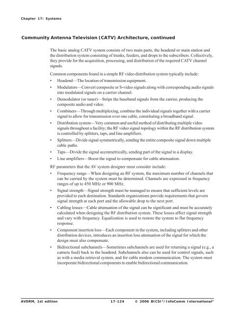
- Page 714 and 715: Chapter 17: Systems Community Anten
- Page 716 and 717: Chapter 17: Systems Community Anten
- Page 718 and 719: Chapter 17: Systems Broadband Syste
- Page 720 and 721: Chapter 17: Systems Headend Signal
- Page 722 and 723: Chapter 17: Systems Headend Signal
- Page 724 and 725: Chapter 17: Systems Baseband versus
- Page 726 and 727: Chapter 17: Systems Baseband versus
- Page 728 and 729: Chapter 17: Systems References Ball
- Page 731: ® Chapter 18 Venues Just as system
- Page 734 and 735: Chapter 18: Venues Designing Places
- Page 736 and 737: Chapter 18: Venues Technical System
- Page 738 and 739: Chapter 18: Venues Designing Museum
- Page 740 and 741: Chapter 18: Venues Designing Primar
- Page 742 and 743: Chapter 18: Venues Security Systems
- Page 744 and 745: Chapter 18: Venues Designing Colleg
- Page 746 and 747: Chapter 18: Venues Uses of Audiovis
- Page 748 and 749: Chapter 18: Venues Audiovisual (AV)
- Page 750 and 751: Chapter 18: Venues Audiovisual (AV)
- Page 752 and 753: Chapter 18: Venues Designing Places
- Page 754 and 755: Chapter 18: Venues Sound Systems, c
- Page 756 and 757: Chapter 18: Venues Sound Systems, c
- Page 758 and 759: Chapter 18: Venues Video Systems Vi
- Page 760 and 761: Chapter 18: Venues Designing Corpor
- Page 762 and 763:
Chapter 18: Venues Audio Conferenci
- Page 764 and 765:
Chapter 18: Venues Introduction, co
- Page 766 and 767:
Chapter 18: Venues Planning, contin
- Page 768 and 769:
Chapter 18: Venues Image Display Te
- Page 770 and 771:
Chapter 18: Venues System Electroni
- Page 772 and 773:
Chapter 18: Venues Clinical Audiovi
- Page 774 and 775:
Chapter 18: Venues Intercom Systems
- Page 776 and 777:
Chapter 18: Venues Special Consider
- Page 778 and 779:
Chapter 18: Venues Designing Hotels
- Page 780 and 781:
Chapter 18: Venues Video-on-Demand
- Page 782 and 783:
Chapter 18: Venues Meeting Manageme
- Page 784 and 785:
Chapter 18: Venues Designing Stadiu
- Page 786 and 787:
Chapter 18: Venues Acoustics The ac
- Page 788 and 789:
Chapter 18: Venues Technical System
- Page 790 and 791:
Chapter 18: Venues Technical System
- Page 792 and 793:
Chapter 18: Venues Planning, contin
- Page 794 and 795:
Chapter 18: Venues Guidelines for V
- Page 796 and 797:
Chapter 18: Venues Visual Paging an
- Page 798 and 799:
Chapter 18: Venues Microphones and
- Page 800 and 801:
Chapter 18: Venues Background Music
- Page 802 and 803:
Chapter 18: Venues Paging Systems P
- Page 804 and 805:
Chapter 18: Venues Designing Entert
- Page 806 and 807:
Chapter 18: Venues Entertainment So
- Page 808 and 809:
Chapter 18: Venues Entertainment So
- Page 810 and 811:
Chapter 18: Venues Infrastructure A
- Page 812 and 813:
Chapter 18: Venues Video Communicat
- Page 814 and 815:
Chapter 18: Venues Sound Reinforcem
- Page 816 and 817:
Chapter 18: Venues Sound Reinforcem
- Page 818 and 819:
Chapter 18: Venues Production Monit
- Page 820 and 821:
Chapter 18: Venues Designing Museum
- Page 822 and 823:
Chapter 18: Venues Personalized Aud
- Page 824 and 825:
Chapter 18: Venues Control Systems,
- Page 826 and 827:
Chapter 18: Venues Designing Legal
- Page 828 and 829:
Chapter 18: Venues Audio Systems, c
- Page 830 and 831:
Chapter 18: Venues Audiovisual (AV)
- Page 832 and 833:
Chapter 18: Venues Signal Distribut
- Page 835:
® Chapter 19 Project Processes Thi
- Page 838 and 839:
Chapter 19: Project Processes Codes
- Page 840 and 841:
Chapter 19: Project Processes Proje
- Page 842 and 843:
Chapter 19: Project Processes Desig
- Page 844 and 845:
Chapter 19: Project Processes Intro
- Page 846 and 847:
Chapter 19: Project Processes Proce
- Page 848 and 849:
Chapter 19: Project Processes Proje
- Page 850 and 851:
Chapter 19: Project Processes Contr
- Page 852 and 853:
Chapter 19: Project Processes Drawi
- Page 854 and 855:
Chapter 19: Project Processes Drawi
- Page 856 and 857:
Chapter 19: Project Processes Codes
- Page 858 and 859:
Chapter 19: Project Processes Socie
- Page 860 and 861:
Chapter 19: Project Processes Refer
- Page 862 and 863:
Bibliography Bibliography, continue
- Page 864 and 865:
Bibliography Bibliography, continue
- Page 867 and 868:
Glossary Terms Numbers 1k tone A so
- Page 869 and 870:
Glossary B backbone cabling Cable a
- Page 871 and 872:
Glossary category 5e Balanced twist
- Page 873 and 874:
Glossary D Data Link layer The Open
- Page 875 and 876:
Glossary electrical service equipme
- Page 877 and 878:
Glossary G gender changer an adapte
- Page 879 and 880:
Glossary in-phase (I) signal The re
- Page 881 and 882:
Glossary logarithm The opposite of
- Page 883 and 884:
Glossary N National Television Syst
- Page 885 and 886:
Glossary patch bay A junction panel
- Page 887 and 888:
Glossary Q quadrature (Q) signal Th
- Page 889 and 890:
Glossary S sabin The metric unit fo
- Page 891 and 892:
Glossary solid conductor cable A ca
- Page 893 and 894:
Glossary technical power system A p
- Page 895 and 896:
Glossary W wavelength cycles. The d
- Page 897 and 898:
Glossary ANS ANSI AP ASCII ASDL ASH
- Page 899 and 900:
Glossary CSMA/CD CSO CSU CTB CTS ca
- Page 901 and 902:
Glossary ER ER ERB ERL ERLE ESD ESS
- Page 903 and 904:
Glossary I I I IAQ IBC IC in-phase
- Page 905 and 906:
Glossary LDAP LEC LED LoS LPD LRV l
- Page 907 and 908:
Glossary O O/A O/H OC OC OCPD OD OF
- Page 909 and 910:
Glossary RF RFC RFI RFI RFI RFID RF
- Page 911 and 912:
Glossary T TBC TCP THD THD+N TIA TM
- Page 913 and 914:
Glossary WAP WEP WG Wi-Fi WLAN WLL
- Page 915 and 916:
Index B background music ..........
- Page 917 and 918:
Index distribution amplifiers .....
- Page 919 and 920:
Index K keying ....................
- Page 921 and 922:
Index P PAG. ......................
- Page 923 and 924:
Index Society of Motion Picture and


