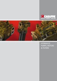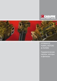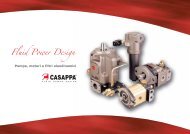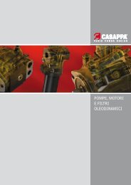
Hydraulic pumps, motors & filters - Casappa
Hydraulic pumps, motors & filters - Casappa
Hydraulic pumps, motors & filters - Casappa

Create successful ePaper yourself
Turn your PDF publications into a flip-book with our unique Google optimized e-Paper software.
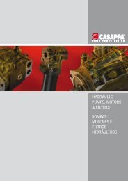
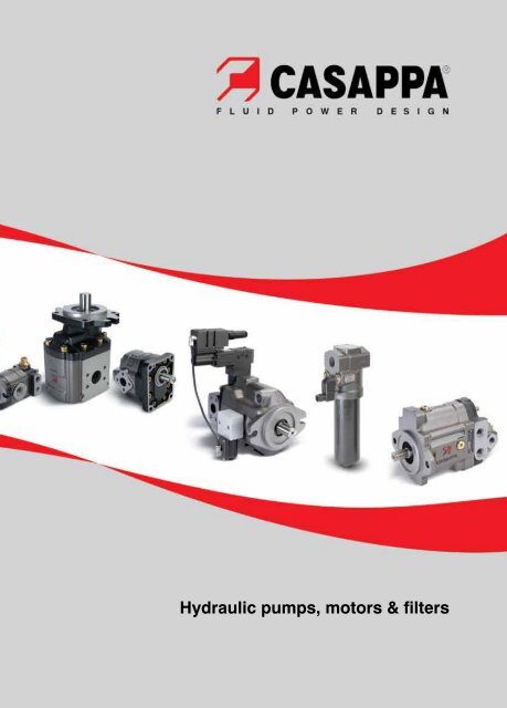
<strong>Hydraulic</strong> <strong>pumps</strong>, <strong>motors</strong> & <strong>filters</strong>
Our passion for high performance in hydraulic drives us.<br />
Constant evolution and a passion for hydraulics; this has been <strong>Casappa</strong>’s strategy, a privately owned company<br />
that has been working for more than fifty years in the field of fluid power transmission.<br />
We design and build the main components for the hydraulic system.<br />
We listen to and work with our customers, from developing a new idea to after-sales service, anywhere around<br />
the globe.<br />
As a tight-knit group of highly motivated and professionally qualified people, we are always ready to meet new<br />
challenges head on.<br />
Thanks to the use of the most modern design engineering, simulation and lab testing technologies, we are<br />
always flexible and ready to quickly modify our offer to meet market demands.<br />
We are convinced that integrating electronics with hydraulics is instrumental to improve hydraulic control circuit<br />
performance. For this reason we continuously invest in research & development, increasing the number of<br />
electronic control and regulation parts in our system.<br />
Quality is our total commitment: that’s why all of our products are thoroughly tested with constant monitoring<br />
including data analysis and traceability. Further, specific tests are perfomed on machines in the field to verify<br />
their effectivness in their actual enviroment.<br />
<strong>Casappa</strong> is worldwide recognized as a highly specialised manufacturer of hydraulic components.<br />
We offer:<br />
Fixed and variable displacement hydraulic <strong>pumps</strong> and <strong>motors</strong><br />
<strong>Hydraulic</strong> valves to control pressure and flow rate<br />
<strong>Hydraulic</strong> <strong>filters</strong><br />
2 DOC 02 R EI
DOC 02 R EI<br />
SALES BY PRODUCT APPLICATIONS<br />
Building & Construction 25%<br />
Truck Market 21%<br />
Agriculture 23%<br />
Material Handling 14%<br />
Industrial 12%<br />
Turf Care 5%<br />
Some of the major companies that rely on our specialised expertise and choose us as an important supplier of<br />
hydraulic components for a wide range of applications include:<br />
AGCO CNH FANTUZZI REGGIANE IR-BOBCAT SCHMIDT TORO<br />
AMMAN-YANMAR DAE DONG GUIMA PALFINGER KOMATSU STILL WAGNER TOYOTA Industrial Equipment<br />
ATLAS COPCO DOOSAN INFRACORE HUNAN SUNWARD MANITOU TEREX VOLVO Compact<br />
CATERPILLAR DAIMLER CHRYSLER HYVA INTERNATIONAL MANITOWOC-GROVE TEXTRON<br />
3
4 DOC 02 R EI
DOC 02 R EI<br />
Product range<br />
Aluminium body gear <strong>pumps</strong> and <strong>motors</strong><br />
Cast iron body gear <strong>pumps</strong> and <strong>motors</strong><br />
Aluminium body gear flow dividers<br />
Cast iron body gear flow dividers<br />
Fixed displacement axial piston <strong>pumps</strong> and <strong>motors</strong><br />
Variable displacement axial piston <strong>pumps</strong><br />
Hand <strong>pumps</strong><br />
5
A complete range of high quality <strong>pumps</strong><br />
and <strong>motors</strong>, the end result of listening<br />
carefully to what customers need and of<br />
working closely with suppliers.<br />
Headquarters:<br />
CASAPPA S.p.A.<br />
43044 Cavalli Di Collecchio<br />
Via Balestrieri,1 - Parma - Italy<br />
Tel. +39 0521 30 41 11 - Fax +39 0521 80 46 00<br />
E-mail: info@casappa.com<br />
www.casappa.com<br />
6 DOC 02 R EI
DOC 02 R EI<br />
<strong>Casappa</strong> offers nothing but the best value to its<br />
customers thanks to the skills and expertise of<br />
its workforce, investments in research and new<br />
technologies, cooperation with leading universities<br />
and electronics-hydraulics integration. <strong>Casappa</strong> offers a wide choice of gear or piston<br />
<strong>pumps</strong> and <strong>motors</strong> for open-circuit applications.<br />
Many functions, such as valves and controls, are<br />
built directly into the products to optimise system<br />
space and costs.<br />
7
POLARIS series<br />
Gear <strong>pumps</strong> and <strong>motors</strong> built in three pieces with an extruded body in high resistance aluminium alloy. The wide choice<br />
of shafts, flanges and ports, in compliance with all international standards (SAE, DIN and EUROPEAN) allow for their use<br />
in an infinite variety of applications.<br />
Displacements from 1,07 cm3 /rev G 0.07 in3 /rev to 91,10 cm3 /rev G 5.56 in3 /rev available in groups 10, 20 and 30.<br />
Max. peak pressure up to 300 bar G 4350 psi.<br />
Max. speed up to 4000 min ‑1 .<br />
Main characteristics<br />
Features<br />
High efficiencies.<br />
Integrated outboard bearings for heavy duty<br />
applications.<br />
Multiple units available in standard version,<br />
common inlet and separated stages.<br />
Electro‑hydraulic fan drive system.<br />
Custom design.<br />
Optional built-in valves<br />
Anticavitation valves.<br />
Maximum pressure relief valves.<br />
Priority valves.<br />
Load‑Sensing priority valves.<br />
By‑pass electric valves.<br />
Proportional relief valves.<br />
Reverse valves.<br />
Aluminium body gear <strong>pumps</strong> and <strong>motors</strong><br />
Displacement Max. continuous<br />
pressure<br />
Max. speed<br />
POLARIS 10 (cm3 /rev G in3 /rev) (bar G psi) (min ‑1 )<br />
PL. 10•1 1,07 G 0.07 260 G 3750 4000<br />
PL. 10•1,5 1,60 G 0.10 260 G 3750 4000<br />
PL. 10•2 2,13 G 0.13 260 G 3750 4000<br />
PL. 10•2,5 2,67 G 0.16 260 G 3750 4000<br />
PL. 10•3,15 3,34 G 0.20 260 G 3750 4000<br />
PL. 10•4 4,27 G 0.26 250 G 3600 4000<br />
PL. 10•5 5,34 G 0.33 250 G 3600 4000<br />
PL. 10•5,8 6,20 G 0.38 230 G 3350 3500<br />
PL. 10•6,3 6,67 G 0.41 230 G 3350 3500<br />
PL. 10•8 8,51 G 0.52 180 G 2600 3500<br />
PL. 10•10 10,67 G 0.65 140 G 2050 3500<br />
POLARIS 20 (cm3 /rev G in3 /rev) (bar G psi) (min ‑1 )<br />
PL. 20•4 4,95 G 0.30 250 G 3600 4000<br />
PL. 20•6,3 6,61 G 0.40 250 G 3600 4000<br />
PL. 20•7,2 7,29 G 0.44 250 G 3600 4000<br />
PL. 20•8 8,26 G 0.50 250 G 3600 3500<br />
PL. 20•9 9,17 G 0.56 250 G 3600 3500<br />
PL. 20•10,5 10,90 G 0.66 250 G 3600 3500<br />
PL. 20•11,2 11,23 G 0.69 250 G 3600 3500<br />
PL. 20•14 14,53 G 0.89 250 G 3600 3500<br />
PL. 20•16 16,85 G 1.03 250 G 3600 3000<br />
PL. 20•19 19,09 G 1.16 200 G 2900 3000<br />
PL. 20•20 21,14 G 1.29 200 G 2900 3000<br />
PL. 20•24,5 24,84 G 1.52 170 G 2450 2500<br />
PL. 20•25 26,42 G 1.61 170 G 2450 2500<br />
PL. 20•27,8 28,21 G 1.72 130 G 1900 2000<br />
PL. 20•31,5 33,03 G 2.01 130 G 1900 2000<br />
POLARIS 30 (cm3 /rev G in3 /rev) (bar G psi) (min ‑1 )<br />
PL. 30•22 21,99 G 1.34 250 G 3600 3000<br />
PL. 30•27 26,70 G 1.63 250 G 3600 3000<br />
PL. 30•34 34,55 G 2.11 240 G 3500 3000<br />
PL. 30•38 39,27 G 2.40 240 G 3500 3000<br />
PL. 30•43 43,98 G 2.68 230 G 3350 3000<br />
PL. 30•51 51,83 G 3.16 210 G 3050 2500<br />
PL. 30•61 61,26 G 3.74 190 G 2750 2500<br />
PL. 30•73 73,82 G 4.50 170 G 2450 2500<br />
PL. 30•82 81,68 G 4.98 160 G 2300 2200<br />
PL. 30•90 91,10 G 5.56 150 G 2200 2200<br />
NOTES<br />
PL. : PLP = pump / PLM = motor<br />
8 DOC 02 R EI
Aluminium body gear <strong>pumps</strong><br />
WHISPER series: low noise emission ‑ reduced pulsations by 75%<br />
Gear <strong>pumps</strong> built in three pieces with an extruded body in high resistance aluminium alloy. WHISPER is a new and<br />
original technology protected by international patents and applied to a family of external gear <strong>pumps</strong> that feature low<br />
noise emissions. The wide choice of shafts, flanges and ports, in compliance with all international standards (SAE, DIN<br />
and EUROPEAN) allow for their use in an infinite variety of applications.<br />
Displacements from 1,12 cm 3 /rev G 0.07 in 3 /rev to 96,85 cm 3 /rev G 5.91 in 3 /rev available in groups 10, 20 and 30.<br />
Max. peak pressure up to 300 bar G 4350 psi.<br />
Max. speed up to 4000 min ‑1 .<br />
Features<br />
High efficiencies .<br />
Low noise emission.<br />
Integrated outboard bearings for heavy duty<br />
applications.<br />
Multiple units.<br />
Custom design.<br />
Optional built-in valves<br />
Anticavitation valves.<br />
Maximum pressure relief valves.<br />
Priority valves.<br />
Load‑Sensing priority valves.<br />
By‑pass electric valves.<br />
DOC 02 R EI<br />
Main characteristics<br />
Displacement Max. continuous<br />
pressure<br />
Max. speed<br />
WHISPER 10 (cm3 /rev G in3 /rev) (bar G psi) (min ‑1 )<br />
WSP 10•1 1,12 G 0.07 260 G 3750 4000<br />
WSP 10•1,5 1,68 G 0.10 260 G 3750 4000<br />
WSP 10•2 2,24 G 0.14 260 G 3750 4000<br />
WSP 10•2,5 2,80 G 0.17 260 G 3750 4000<br />
WSP 10•3,15 3,48 G 0.21 260 G 3750 4000<br />
WSP 10•4 4,45 G 0.27 250 G 3600 4000<br />
WSP 10•5 5,60 G 0.34 250 G 3600 4000<br />
WSP 10•5,8 6,51 G 0.40 230 G 3350 3500<br />
WSP 10•6,3 7,00 G 0.43 230 G 3350 3500<br />
WSP 10•8 8,92 G 0.54 180 G 2600 3500<br />
WSP 10•10 11,20 G 0.68 140 G 2050 3500<br />
WHISPER 20 (cm3 /rev G in3 /rev) (bar G psi) (min ‑1 )<br />
WSP 20•4 5,25 G 0.32 250 G 3600 4000<br />
WSP 20•6,3 7,00 G 0.43 250 G 3600 4000<br />
WSP 20•7,2 7,72 G 0.47 250 G 3600 4000<br />
WSP 20•8 8,74 G 0.53 250 G 3600 3500<br />
WSP 20•9 9,65 G 0.59 250 G 3600 3500<br />
WSP 20•10,5 11,54 G 0.70 250 G 3600 3500<br />
WSP 20•11,2 11,89 G 0.73 250 G 3600 3500<br />
WSP 20•14 15,39 G 0.94 250 G 3600 3500<br />
WSP 20•16 17,84 G 1.09 250 G 3600 3000<br />
WSP 20•19 20,22 G 1.23 200 G 2900 3000<br />
WSP 20•20 22,38 G 1.37 200 G 2900 3000<br />
WSP 20•24,5 26,30 G 1.60 170 G 2450 2500<br />
WSP 20•25 27,98 G 1.71 170 G 2450 2500<br />
WSP 20•27,8 29,87 G 1.82 130 G 1900 2000<br />
WSP 20•31,5 34,98 G 2.13 130 G 1900 2000<br />
WHISPER 30 (cm3 /rev G in3 /rev) (bar G psi) (min ‑1 )<br />
WSP 30•22 23,38 G 1.43 250 G 3600 3000<br />
WSP 30•27 28,39 G 1.73 250 G 3600 3000<br />
WSP 30•34 36,74 G 2.24 240 G 3500 3000<br />
WSP 30•38 41,75 G 2.55 240 G 3500 3000<br />
WSP 30•43 46,76 G 2.85 230 G 3350 3000<br />
WSP 30•51 55,10 G 3.36 210 G 3050 2500<br />
WSP 30•61 65,12 G 3.97 190 G 2750 2500<br />
WSP 30•73 78,48 G 4.79 170 G 2450 2500<br />
WSP 30•82 86,83 G 5.30 160 G 2300 2200<br />
WSP 30•90 96,85 G 5.91 150 G 2200 2200<br />
9
KAPPA and KAPPA COMPACT series<br />
Gear <strong>pumps</strong> and <strong>motors</strong> made of cast iron in two pieces. A rigid and compact structure that makes it possible to<br />
incorporate a number of functions in a limited space.<br />
Wide range of displacements: from 4,95 cm 3 /rev G 0.30 in 3 /rev to 150,79 cm 3 /rev G 9.20 in 3 /rev available in groups 20, 30<br />
and 40.<br />
Max. peak pressure up to 330 bar G 4800 psi.<br />
Max. speed up to 4000 min ‑1 .<br />
Features<br />
High operating pressures .<br />
High efficiency at high temperature.<br />
Low noise emission.<br />
Exceptional working life expectancy.<br />
Solid and compact design.<br />
Custom design.<br />
Optional built-in valves<br />
Antishock and anticavitation valves.<br />
Priority valves.<br />
Load‑Sensing priority valves.<br />
By‑pass electric valves.<br />
Cast iron body gear <strong>pumps</strong> and <strong>motors</strong><br />
Main characteristics<br />
Displacement Max. continuous<br />
pressure<br />
Max. speed<br />
KAPPA 20 (cm3 /rev G in3 /rev) (bar G psi) (min ‑1 )<br />
K. 20•4 4,95 G 0.30 285 G 4150 4000<br />
K. 20•6,3 6,61 G 0.40 285 G 4150 4000<br />
K. 20•8 8,26 G 0.50 285 G 4150 3500<br />
K. 20•11,2 11,23 G 0.69 275 G 4000 3500<br />
K. 20•14 14,53 G 0.89 265 G 3850 3500<br />
K. 20•16 16,85 G 1.03 260 G 3750 3000<br />
K. 20•20 21,14 G 1.29 210 G 3050 3000<br />
K. 20•25 26,42 G 1.61 180 G 2600 2500<br />
K. 20•31,5 33,03 G 2.01 140 G 2050 2500<br />
KAPPA 30 (cm3 /rev G in3 /rev) (bar G psi) (min ‑1 )<br />
K. 30•27 26,70 G 1.63 280 G 4050 3000<br />
K. 30•34 34,56 G 2.11 260 G 3750 3000<br />
K. 30•38 39,27 G 2.40 260 G 3750 3000<br />
K. 30•43 43,98 G 2.68 250 G 3600 3000<br />
K. 30•51 51,83 G 3.16 230 G 3350 2500<br />
K. 30•56 56,54 G 3.45 215 G 3100 2500<br />
K. 30•61 61,26 G 3.74 200 G 2900 2500<br />
K. 30•73 73,82 G 4.50 180 G 2600 2500<br />
KAPPA compact 30 (cm3 /rev G in3 /rev) (bar G psi) (min ‑1 )<br />
K. 30•22 21,99 G 1.34 280 G 4050 3000<br />
K. 30•27 26,70 G 1.63 280 G 4050 3000<br />
K. 30•31 30,63 G 1.87 260 G 3750 3000<br />
K. 30•34 34,56 G 2.11 260 G 3750 3000<br />
K. 30•38 39,27 G 2.40 260 G 3750 3000<br />
K. 30•41 41,62 G 2.54 250 G 3600 3000<br />
K. 30•43 43,98 G 2.68 250 G 3600 3000<br />
K. 30•46 46,34 G 2.83 250 G 3600 3000<br />
K. 30•51 51,83 G 3.16 230 G 3350 2500<br />
K. 30•56 56,54 G 3.45 215 G 3100 2500<br />
K. 30•61 61,26 G 3.74 200 G 2900 2500<br />
K. 30•73 73,82 G 4.50 180 G 2600 2500<br />
KAPPA compact 40 (cm3 /rev G in3 /rev) (bar G psi) (min ‑1 )<br />
K. 40•63 61,43 G 3.75 300 G 4350 2800<br />
K. 40•73 72,60 G 4.43 300 G 4350 2800<br />
K. 40•87 86,56 G 5.28 280 G 4050 2800<br />
K. 40•109 108,90 G 6.64 250 G 3600 2800<br />
K. 40•121 121,80 G 7.43 230 G 3350 2500<br />
K. 40•133 134,03 G 8.18 220 G 3200 2500<br />
K. 40•151 150,79 G 9.20 200 G 2900 2500<br />
NOTES<br />
K. : KP = pump / KM = motor<br />
10 DOC 02 R EI
Cast iron body gear <strong>pumps</strong> and <strong>motors</strong><br />
FORMULA and FORMULA SFP series<br />
Gear <strong>pumps</strong> made of cast iron in two pieces, ideal for truck application.<br />
Displacements from 8,26 cm 3 /rev G 0.50 in 3 /rev to 150,79 cm 3 /rev G 9.20 in 3 /rev available in groups 20, 30, 35 and 40.<br />
Max. peak pressure up to 325 bar G 4700 psi.<br />
Max. speed up to 3000 min ‑1 .<br />
Features<br />
High performance also at very low speed.<br />
Different ports position availability.<br />
Low noise emission.<br />
Shaft seal system no leakage guarantee.<br />
Modular design.<br />
Direct mounting on the PTOs.<br />
DOC 02 R EI<br />
Main characteristics<br />
Displacement Max. continuous<br />
pressure<br />
Max. speed<br />
FORMULA 20 (cm3 /rev G in3 /rev) (bar G psi) (min ‑1 )<br />
FP 20•8 8,26 G 0.50 280 G 4050 2000<br />
FP 20•11,2 11,23 G 0.69 280 G 4050 2000<br />
FP 20•16 16,85 G 1.03 280 G 4050 2000<br />
FP 20•20 21,14 G 1.29 260 G 3750 2000<br />
FP 20•25 26,42 G 1.61 220 G 3200 2000<br />
FP 20•31,5 33,03 G 2.01 190 G 2750 1800<br />
FP 20•36 35,94 G 2.19 170 G 2450 1800<br />
FP 20•40 39,64 G 2.42 160 G 2300 1800<br />
FORMULA 30 (cm3 /rev G in3 /rev) (bar G psi) (min ‑1 )<br />
FP 30•17 17,28 G 1.05 290 G 4200 3000<br />
FP 30•27 26,70 G 1.63 290 G 4200 3000<br />
FP 30•34 34,56 G 2.11 280 G 4050 2800<br />
FP 30•38 39,27 G 2.40 280 G 4050 2800<br />
FP 30•43 43,98 G 2.68 270 G 3900 2500<br />
FP 30•51 51,83 G 3.16 240 G 3500 2500<br />
FP 30•61 61,26 G 3.74 220 G 3200 2000<br />
FP 30•73 73,82 G 4.50 200 G 2900 1800<br />
FP 30•82 81,68 G 4.98 190 G 2750 1800<br />
FP 30•100 100,52 G 6.16 180 G 2600 1800<br />
FP 30•125 125,66 G 7.67 160 G 2300 1800<br />
FORMULA 40 (cm3 /rev G in3 /rev) (bar G psi) (min ‑1 )<br />
FP 40•63 61,43 G 3.75 290 G 4200 2700<br />
FP 40•73 72,60 G 4.43 280 G 4050 2700<br />
FP 40•87 86,56 G 5.28 260 G 3750 2700<br />
FP 40•109 108,90 G 6.64 240 G 3500 2700<br />
FP 40•133 134,03 G 8.18 220 G 3200 2500<br />
FP 40•151 150,79 G 9.20 180 G 2600 2500<br />
FORMULA SFP 30 (cm3 /rev G in3 /rev) (bar G psi) (min ‑1 )<br />
SFP 30•34 35,43 G 2.16 280 G 4050 2800<br />
SFP 30•43 45,09 G 2.75 270 G 3900 2500<br />
SFP 30•51 53,14 G 3.24 250 G 3600 2500<br />
SFP 30•61 62,80 G 3.83 230 G 3350 2500<br />
SFP 30•73 75,68 G 4.62 205 G 2950 2250<br />
SFP 30•82 83,74 G 5.11 195 G 2800 2250<br />
FORMULA SFP 35 (cm3 /rev G in3 /rev) (bar G psi) (min ‑1 )<br />
SFP 35•90 95,99 G 5.86 230 G 3350 2250<br />
SFP 35•100 104,92 G 6.40 220 G 3200 2250<br />
SFP 35•112 118,31 G 7.22 205 G 2950 2250<br />
11
MAGNUM series<br />
Gear <strong>pumps</strong> and <strong>motors</strong> made of cast iron in three pieces. An extremely versatile and reliable design, also in the most<br />
extreme operating conditions.<br />
Displacements from 17,28 cm 3 /rev G 1.05 in 3 /rev to 125,63 cm 3 /rev G 7.66 in 3 /rev available in groups 30 and 35.<br />
Max. peak pressure up to 320 bar G 4650 psi.<br />
Max. speed up to 3000 min ‑1 .<br />
Features<br />
Wide range of drive shafts and flanges in SAE<br />
version.<br />
More choices of port locations.<br />
Integrated outboard bearings for heavy duty<br />
applications.<br />
Multiple units available in standard version,<br />
common inlet and separated stages.<br />
Exceptional working life expectancy.<br />
Cast iron body gear <strong>pumps</strong> and <strong>motors</strong><br />
Main characteristics<br />
Displacement Max. continuous<br />
pressure<br />
Max. speed<br />
MAGNUM 30 (cm3 /rev G in3 /rev) (bar G psi) (min ‑1 )<br />
HD. 30•17 17,28 G 1.05 280 G 4050 3000<br />
HD. 30•22 21,99 G 1.34 280 G 4050 3000<br />
HD. 30•24 24,03 G 1.47 280 G 4050 3000<br />
HD. 30•27 26,70 G 1.63 280 G 4050 3000<br />
HD. 30•34 34,56 G 2.11 270 G 3900 3000<br />
HD. 30•38 39,27 G 2.40 270 G 3900 3000<br />
HD. 30•43 43,98 G 2.68 260 G 3750 3000<br />
HD. 30•51 51,83 G 3.16 230 G 3350 2500<br />
HD. 30•56 56,55 G 3.45 215 G 3100 2500<br />
HD. 30•61 61,26 G 3.74 200 G 2900 2000<br />
HD. 30•73 73,82 G 4.50 190 G 2750 1700<br />
HD. 30•82 81,68 G 4.98 170 G 2450 1500<br />
MAGNUM 35 (cm3 /rev G in3 /rev) (bar G psi) (min ‑1 )<br />
HD. 35•40 40,46 G 2.47 270 G 3900 3000<br />
HD. 35•50 51,10 G 3.12 270 G 3900 3000<br />
HD. 35•63 63,88 G 3.90 270 G 3900 3000<br />
HD. 35•71 72,40 G 4.42 250 G 3600 3000<br />
HD. 35•80 80,91 G 4.94 250 G 3600 3000<br />
HD. 35•90 91,56 G 5.59 230 G 3350 2700<br />
HD. 35•100 100,08 G 6.10 210 G 3050 2700<br />
HD. 35•112 112,85 G 6.88 190 G 2750 2700<br />
HD. 35•125 125,63 G 7.66 170 G 2450 2500<br />
NOTES<br />
HD. : HDP = pump / HDM = motor<br />
12 DOC 02 R EI
Aluminium body gear flow dividers<br />
POLARIS series<br />
Gear flow dividers made of high resistance aluminium alloy. These components can be used as flow equalizers, flow<br />
dividers and pressure intensifiers.<br />
Displacements from 2,14 cm 3 /rev G 0.13 in 3 /rev to 33,03 cm 3 /rev G 2.01 in 3 /rev available in groups 10 and 20.<br />
Max. peak pressure up to 280 bar G 4050 psi.<br />
Features<br />
Modular design.<br />
Accurate division of flow.<br />
Built‑in relief valves.<br />
Combinations between different groups.<br />
DOC 02 R EI<br />
Main characteristics<br />
Displacement Max. continuous<br />
outlet pressure<br />
Max. speed<br />
POLARIS 10 (cm3 /rev G in3 /rev) (bar G psi) (min ‑1 )<br />
PLD 10•2 2,14 G 0.13 250 G 3600 4200<br />
PLD 10•3,15 3,34 G 0.20 250 G 3600 3990<br />
PLD 10•4 4,27 G 0.26 250 G 3600 3940<br />
PLD 10•5 5,34 G 0.33 250 G 3600 3680<br />
PLD 10•6,3 6,67 G 0.41 250 G 3600 3500<br />
POLARIS 20 (cm3 /rev G in3 /rev) (bar G psi) (min ‑1 )<br />
PLD 20•4 4,95 G 0.30 250 G 3600 4100<br />
PLD 20•6,3 6,61 G 0.40 250 G 3600 3970<br />
PLD 20•8 8,26 G 0.50 250 G 3600 3850<br />
PLD 20•11,2 11,23 G 0.69 250 G 3600 3660<br />
PLD 20•14 14,53 G 0.89 250 G 3600 3460<br />
PLD 20•16 16,85 G 1.03 200 G 2900 3335<br />
PLD 20•20 21,14 G 1.29 200 G 2900 3125<br />
PLD 20•25 26,42 G 1.61 200 G 2900 2900<br />
PLD 20•31,5 33,03 G 2.01 200 G 2900 2660<br />
13
MAGNUM series<br />
Gear flow dividers made of cast iron. These components can be used as flow equalizers, flow dividers and pressure<br />
intensifiers.<br />
Displacements from 17,28 cm 3 /rev G 1.05 in 3 /rev to 125,63 cm 3 /rev G 7.66 in 3 /rev available in groups 30 and 35.<br />
Max. peak pressure up to 320 bar G 4650 psi.<br />
Features<br />
Modular design.<br />
Accurate division of flow.<br />
High flow.<br />
Combinations between different groups.<br />
Cast iron body gear flow dividers<br />
Main characteristics<br />
Displacement Max. continuous<br />
outlet pressure<br />
Max. speed<br />
MAGNUM 30 (cm3 /rev G in3 /rev) (bar G psi) (min ‑1 )<br />
HDD 30•17 17,28 G 1.05 280 G 4050 3000<br />
HDD 30•22 21,99 G 1.34 280 G 4050 3000<br />
HDD 30•27 26,70 G 1.63 280 G 4050 3000<br />
HDD 30•34 34,56 G 2.11 270 G 3900 3000<br />
HDD 30•43 43,98 G 2.68 260 G 3750 3000<br />
HDD 30•51 51,83 G 3.16 230 G 3350 2500<br />
HDD 30•61 61,26 G 3.74 200 G 2900 2000<br />
HDD 30•73 73,82 G 4.50 190 G 2750 1700<br />
HDD 30•82 81,68 G 4.98 170 G 2450 1500<br />
MAGNUM 35 (cm3 /rev G in3 /rev) (bar G psi) (min ‑1 )<br />
HDD 35•50 51,10 G 3.12 270 G 3900 3000<br />
HDD 35•63 63,88 G 3.90 270 G 3900 3000<br />
HDD 35•71 72,40 G 4.42 250 G 3600 3000<br />
HDD 35•80 80,91 G 4.94 250 G 3600 3000<br />
HDD 35•90 91,56 G 5.59 230 G 3350 2700<br />
HDD 35•100 100,08 G 6.10 210 G 3050 2700<br />
HDD 35•112 112,85 G 6.88 190 G 2750 2700<br />
HDD 35•125 125,63 G 7.66 170 G 2450 2500<br />
14 DOC 02 R EI
Fixed displacement axial piston <strong>pumps</strong><br />
STRADA series<br />
Fixed displacement bent axis piston <strong>pumps</strong>. STRADA <strong>pumps</strong> are ideally suited for PTOs applications in vehicles.<br />
Displacements from 40,9 cm 3 /rev G 2.49 in 3 /rev to 110 cm 3 /rev G 6.71 in 3 /rev available in groups 32 and 37.<br />
Max. peak pressure up to 400 bar G 5800 psi.<br />
Max. speed up to 2950 min ‑1 .<br />
Features<br />
Low noise level.<br />
Direct mounting on the PTOs.<br />
Compact design.<br />
High volumetric, mechanical and overall efficiency.<br />
Available in ISO and UNI standard.<br />
DOC 02 R EI<br />
Main characteristics<br />
Displacement Max. continuous<br />
pressure<br />
Max. speed<br />
STRADA 32 (cm3 /rev G in3 /rev) (bar G psi) (min ‑1 )<br />
BAP 32•40 40,90 G 2.49 350 G 5100 2950<br />
BAP 32•50 50,10 G 3.06 350 G 5100 2750<br />
BAP 32•63 63,00 G 3.84 350 G 5100 2450<br />
BAP 32•71 71,60 G 4.37 315 G 4600 2250<br />
BAP 32•80 78,30 G 4.78 315 G 4600 2200<br />
STRADA 37 (cm3 /rev G in3 /rev) (bar G psi) (min ‑1 )<br />
BAP 37•80 79,10 G 4.83 350 G 5100 2500<br />
BAP 37•110 110,00 G 6.71 300 G 4350 2300<br />
15
PLATA series<br />
Fixed displacement axial piston <strong>pumps</strong> and <strong>motors</strong> swash plate design for open circuit applications. The design itself<br />
is extremely compact while integrating a number of functions, with an electrically controlled valve on the pump and<br />
antishock valves on the motor.<br />
Unidirectional <strong>pumps</strong> LFP48: displacements from 27 cm 3 /rev G 1.65 in 3 /rev to 48,2 cm 3 /rev G 2.94 in 3 /rev.<br />
Reversible <strong>motors</strong> LFM30: displacements from 22 cm 3 /rev G 1.34 in 3 /rev to 30,2 cm 3 /rev G 1.84 in 3 /rev.<br />
Max. peak pressure up to 350 bar G 5100 psi.<br />
Pumps features<br />
Three‑position electrically controlled valve with relief<br />
valve.<br />
Electronic control of the rotor start‑up and stop ramps.<br />
Rotation reverse with controlled delay.<br />
Easy integration with the machine cabin controls.<br />
Auxiliary gear pump with common suction, available<br />
with either cast‑iron or aluminium body.<br />
Motors features<br />
Reversible rotation with integral antishock valves.<br />
European and SAE standard mounting flanges.<br />
Side or rear inlet options.<br />
Compact size.<br />
Fixed displacement axial piston <strong>pumps</strong> and <strong>motors</strong><br />
Main characteristics<br />
Displacement Max. continuous<br />
pressure<br />
Max. speed<br />
PLATA <strong>pumps</strong> (cm3 /rev G in3 /rev) (bar G psi) (min ‑1 )<br />
LFP 48•27 27,00 G 1.65 280 G 4050 2600<br />
LFP 48•34 34,00 G 2.07 280 G 4050 2600<br />
LFP 48•36,7 36,70 G 2.24 280 G 4050 2600<br />
LFP 48•45,5 45,50 G 2.78 280 G 4050 2600<br />
LFP 48•48 48,20 G 2.94 280 G 4050 2600<br />
PLATA <strong>motors</strong> (cm3 /rev G in3 /rev) (bar G psi) (min ‑1 )<br />
LFM 30•22 22,00 G 1.34 280 G 4050 4900<br />
LFM 30•26,5 26,50 G 1.62 280 G 4050 4800<br />
LFM 30•28,5 28,50 G 1.74 280 G 4050 4700<br />
LFM 30•30,2 30,20 G 1.84 280 G 4050 4500<br />
16 DOC 02 R EI
Variable displacement axial piston <strong>pumps</strong><br />
PLATA LVP series<br />
Variable displacement axial piston <strong>pumps</strong> swash plate design. PLATA <strong>pumps</strong> are ideally suited for medium and high<br />
pressure open circuit applications.<br />
Displacements from 28,49 cm 3 /rev G 1.74 in 3 /rev to 87,90 cm 3 /rev G 5.37 in 3 /rev.<br />
Max. peak pressure up to 350 bar G 5100 psi.<br />
Max. speed up to 3000 min ‑1 .<br />
Features<br />
Energy savings.<br />
Low noise emission.<br />
Short response time.<br />
Drive shaft bearing suitable for radial and axial loads.<br />
Multiple combinations.<br />
Controls<br />
Pressure compensator.<br />
Flow and pressure compensator (Load‑Sensing).<br />
Torque limiter.<br />
Electrohydraulic servocontrols.<br />
DOC 02 R EI<br />
Main characteristics<br />
Max<br />
displacement<br />
Max. continuous<br />
pressure<br />
Max. speed<br />
PLATA LVP (cm3 /rev G in3 /rev) (bar G psi) (min ‑1 )<br />
LVP 30 28,49 G 1.74 280 G 4050 3000<br />
LVP 48 45,47 G 2.77 280 G 4050 2600<br />
LVP 75 75,53 G 4.61 280 G 4050 2200<br />
LVP 90 87,90 G 5.37 250 G 3600 1850<br />
17
MVP series<br />
Variable displacement axial piston <strong>pumps</strong> swash plate design ideally suited for open circuit in mobile hydraulic<br />
applications. The compact design allows to be mounted directly on engine <strong>motors</strong>.<br />
Displacements from 28,5 cm 3 /rev G 1.74 in 3 /rev to 84 cm 3 /rev G 5.12 in 3 /rev.<br />
Max. peak pressure up to 350 bar G 5100 psi.<br />
Max. speed up to 3000 min ‑1 .<br />
Features<br />
Exceptional working life expectancy.<br />
Low noise emission.<br />
Drive shaft bearing suitable for radial and axial<br />
loads.<br />
Multiple combinations.<br />
Controls<br />
Min. and max. displacement limiter.<br />
Pressure compensator.<br />
Flow and pressure compensator (Load‑Sensing).<br />
Torque limiter.<br />
Variable displacement axial piston <strong>pumps</strong><br />
Main characteristics<br />
Max<br />
displacement<br />
Max. continuous<br />
pressure<br />
Max. speed<br />
MVP (cm3 /rev G in3 /rev) (bar G psi) (min ‑1 )<br />
MVP 30.28 28,50 G 1.74 280 G 4050 3000<br />
MVP 30.34 33,60 G 2.05 250 G 3600 3000<br />
MVP 48.45 45,00 G 2.75 280 G 4050 3000<br />
MVP 48.53 53,00 G 3.23 250 G 3600 2800<br />
MVP 60.60 60,00 G 3.66 280 G 4050 2700<br />
MVP 60.72 72,00 G 4.39 280 G 4050 2500<br />
MVP 60.84 84,00 G 5.12 250 G 3600 2500<br />
18 DOC 02 R EI
Variable displacement axial piston <strong>pumps</strong><br />
PLATA SVP ‑ DVP series<br />
Variable displacement axial piston <strong>pumps</strong> swash plate design for open circuit applications. SVP single flow, DVP dual<br />
flow on piston pump and an additional piggybacked gear pump. The automatic overall torque limiter allows to optimize<br />
the performance of themachine. SVP and DVP <strong>pumps</strong> has been designed specifically for mini excavators where<br />
compactness and ease of installation are critical.<br />
Piston pump: displacements from 7,8 cm 3 /rev G 0.48 in 3 /rev to 30 cm 3 /rev G 1.83 in 3 /rev.<br />
Gear pump: displacements from 4,95 cm 3 /rev G 0.30 in 3 /rev to 21,14 cm 3 /rev G 1.29 in 3 /rev.<br />
Max. speed up to 2600 min ‑1 .<br />
SVP and DVP features<br />
Compact design.<br />
Torque limiter.<br />
Energy savings.<br />
Low noise emission.<br />
Long service life.<br />
DOC 02 R EI<br />
Main characteristics<br />
Max<br />
displacement<br />
Max. continuous<br />
pressure<br />
Max. speed<br />
PLATA SVP (cm3 /rev G in3 /rev) (bar G psi) (min ‑1 )<br />
SVP 7,8 15,60 G 0.95 210 G 3050 2600<br />
SVP 8 16,00 G 0.98 210 G 3050 2600<br />
SVP 8,5 17,00 G 1.04 210 G 3050 2600<br />
SVP 9 18,00 G 1.10 210 G 3050 2600<br />
SVP 10 20,00 G 1.22 210 G 3050 2600<br />
SVP 11 22,00 G 1.34 210 G 3050 2600<br />
SVP 12,5 25,00 G 1.53 210 G 3050 2600<br />
SVP 14 28,00 G 1.71 210 G 3050 2600<br />
SVP 15 30,00 G 1.83 210 G 3050 2600<br />
PLATA DVP (cm3 /rev G in3 /rev) (bar G psi) (min ‑1 )<br />
DVP 7,8 7,80x2 G 0.48x2 210 G 3050 2600<br />
DVP 8 8,00x2 G 0.49x2 210 G 3050 2600<br />
DVP 8,5 8,50x2 G 0.52x2 210 G 3050 2600<br />
DVP 9 9,00x2 G 0.55x2 210 G 3050 2600<br />
DVP 10 10,00x2 G 0.61x2 210 G 3050 2600<br />
DVP 11 11,00x2 G 0.67x2 210 G 3050 2600<br />
DVP 12,5 12,50x2 G 0.76x2 210 G 3050 2600<br />
DVP 14 14,00x2 G 0.85x2 210 G 3050 2600<br />
DVP 15 15,00x2 G 0.91x2 210 G 3050 2600<br />
Gear pump (cm3 /rev G in3 /rev) (bar G psi) (min ‑1 )<br />
KP 20•4 4,95 G 0.30 285 G 4150 2600<br />
KP 20•6,3 6,61 G 0.40 285 G 4150 2600<br />
KP 20•8 8,26 G 0.50 285 G 4150 2600<br />
KP 20•11,2 11,23 G 0.69 275 G 4000 2600<br />
KP 20•14 14,53 G 0.89 265 G 3850 2600<br />
KP 20•16 16,85 G 1.03 260 G 3750 2600<br />
KP 20•20 21,14 G 1.29 210 G 3050 2600<br />
19
Up Easy series<br />
Double acting hand <strong>pumps</strong> providing flow in both directions of lever movement.<br />
Displacement from 12 cm 3 /cycle G 0.73 in 3 /cycle to 45 cm 3 /cycle G 2.75 in 3 /cycle.<br />
Max. pressure 315 bar G 4600 psi.<br />
Features<br />
New interchange modular design for maximum<br />
flexibility.<br />
Same pumping group with or without reservoir.<br />
Suitable for auxiliary or emergency applications.<br />
Main characteristics<br />
Hand <strong>pumps</strong><br />
Displacement Max. pressure<br />
Up Easy (cm3 /cycle G in3 /cycle) (bar G psi)<br />
EP 12 12 G 0.73 315 G 4600<br />
EP 25 25 G 1.53 250 G 3600<br />
EP 45 45 G 2.75 220 G 3200<br />
20 DOC 02 R EI
DOC 02 R EI<br />
Product range<br />
Suction <strong>filters</strong><br />
In line <strong>filters</strong> spin-on<br />
Tank mounted return line <strong>filters</strong><br />
In line medium and high pressure <strong>filters</strong><br />
Accessories<br />
21
IKRON “Fluid Filtration”, real specialist in<br />
designing and manufacturing of hydraulic<br />
<strong>filters</strong>. More than fifty years of experience<br />
taught <strong>Casappa</strong> just how important filtering is<br />
to optimise hydraulic control system efficiency<br />
and to extend component service life.<br />
Since its foundation, IKRON has followed the<br />
ISO 9001:2000 procedures, guaranteeing<br />
the care and professionalism for which its<br />
production has always been distinguished,<br />
from design to delivery. This is why our<br />
customers rely on IKRON every day.<br />
IKRON S.r.l.<br />
43044 Lemignano Di Collecchio<br />
Via Prampolini, 2 - Parma - Italy<br />
Tel. +39 0521 30 49 11 - Fax +39 0521 30 49 00<br />
E-mail: info@ikron.it<br />
www.ikron.it<br />
22 DOC 02 R EI
DOC 02 R EI<br />
IKRON uses virtual simulation tools during<br />
the design phase to analyse and predict how<br />
its products will behave when installed in the<br />
hydraulic circuit.<br />
Ikron offers a wide range of <strong>filters</strong> and accessories.<br />
Suction <strong>filters</strong>, return <strong>filters</strong>, in line spin-on <strong>filters</strong>,<br />
medium and high pressure <strong>filters</strong>.<br />
Clogging indicators, level and temperature gauges,<br />
filler breathers.<br />
23
Suction <strong>filters</strong><br />
The tank submerged suction <strong>filters</strong> are designed to be fitted directly on pump intake and provide versatility to safeguard<br />
the hydraulic components from contaminating particles.<br />
HF 410‑412 series<br />
By‑pass valve.<br />
Magnetic set.<br />
Main characteristics<br />
Nominal flow up to Degree of filtration*<br />
Type (l/min G US gpm) MS (µm) MI (µm)<br />
HF 410 300 G 79 90 25‑60‑125‑250<br />
HF 412 140 G 37 90 25‑60‑125‑250<br />
In line <strong>filters</strong> spin-on<br />
These <strong>filters</strong> are specifically designed to be connected on the suction or in the return line of the hydraulic circuit and<br />
provide versatility to safeguard the circuit components from contaminating particles.<br />
Main characteristics<br />
HF 620-625 series<br />
Easy filtering elements replacement.<br />
Differential control of the clogging values.<br />
HF 650 series<br />
Easy filtering elements replacement.<br />
High filtration performances.<br />
High resistance filtering elements.<br />
Filters and accessories<br />
Nominal flow up to Operating pressure Degree of filtration*<br />
Type (l/min G US gpm) (bar G psi) FG (µm) MS (µm) SP (µm) RP (µm)<br />
HF 620 400 G 106 12 G 174 10‑25 60‑90‑125 10‑25<br />
HF 625 200 G 53 25 G 360 10‑25 60‑90‑125 10‑25<br />
HF 650 180 G 48 35 G 510 3‑6‑10‑16‑25 10‑25<br />
NOTES<br />
(*): FG = micro‑fibre glass / MS = zinc plated steel wire mesh / MI = stainless steel wire mesh / SP = cellulose / RP = reinforced cellulose<br />
24 DOC 02 R EI
Filters and accessories<br />
Tank mounted return line <strong>filters</strong><br />
These <strong>filters</strong> are specifically designed to be directly connected on the hydraulic circuits return line and provide versatility<br />
to safeguard the circuit components from contaminating particles.<br />
Main characteristics<br />
DOC 02 R EI<br />
HF 502 series<br />
Minimum extension from the tank.<br />
Interchangeable with HF 550 and HF 554 series.<br />
HF 547 series<br />
Air breather (available also with pressurized version).<br />
Antisplash system.<br />
Anodized housing.<br />
Flange with four holes (only HF 547‑20).<br />
HF 550 series<br />
Oversize filtering surface.<br />
Multilayer system.<br />
Filler cap.<br />
HF 554 series<br />
Oversize filtering surface.<br />
Multilayer system.<br />
Air breather (available also with pressurized version).<br />
Antisplash system.<br />
Anodized housing.<br />
HF 570-575 series<br />
Inside‑to‑outside direction of flow filtration.<br />
Full flow magnetic pre‑filtration on the hydraulic return line.<br />
Filler cap.<br />
Nominal flow up to Operating pressure Degree of filtration*<br />
Type (l/min G US gpm) (bar G psi) FG (µm) FB (µm) MS (µm) MI (µm) SP (µm) RP (µm)<br />
HF 502 800 G 210 8 G 115 3‑6‑10‑25 60‑125 90‑250 25 10‑25 10‑25<br />
HF 550 600 G 158 8 G 115 3‑6‑10‑25 60‑125 90‑250 25 10‑25 10‑25<br />
HF 547 200 G 53 8 G 115 3‑6‑10‑25 60‑125 90‑250 25 10‑25 10‑25<br />
HF 554 200 G 53 8 G 115 3‑6‑10‑25 60‑125 90‑250 25 10‑25 10‑25<br />
HF 570 1000 G 264 8 G 115 10‑25 10‑25<br />
HF 575 1000 G 264 8 G 115 10‑25 10‑25<br />
NOTES<br />
(*): FG = micro‑fibre glass / FB = phosphor bronze / MS = zinc plated steel wire mesh / MI = stainless steel wire mesh/ SP = cellulose /<br />
RP = reinforced cellulose<br />
25
In line medium and high pressure <strong>filters</strong><br />
The in‑line medium and high pressure <strong>filters</strong> are specifically designed to be connected on the pressure line of<br />
the hydraulic circuit and provide versatility to safeguard the circuit components from contaminating particles.<br />
HF 705 series<br />
Sintered bronze filter element.<br />
Bidirectional flow.<br />
Compact design.<br />
HF 725 series<br />
CETOP 3 connections with reference to ISO4401.<br />
Operating pressure 350 bar G 5100 psi.<br />
Modular assembly.<br />
Compact design and low weight.<br />
HF 735 series<br />
Compact design and low weight.<br />
Multilayer system.<br />
Also to be flanged directly on valve blocks and hydraulic Power‑Pack.<br />
Filtration ratio ß x ≥ 200.<br />
HF 760 series<br />
Multilayer system.<br />
Wide range 20 ‑ 30 ‑ 40.<br />
High ratio flow/head dimension.<br />
Filtration ratio ß x x ≥ 200.<br />
Main characteristics<br />
HF 745 series<br />
Compact design and low weight.<br />
Great interchangeability.<br />
Multilayer system.<br />
Filtration ratio ß x x ≥ 200.<br />
Type<br />
Nominal flow<br />
up to<br />
(l/min G US gpm)<br />
Operating<br />
pressure<br />
(bar G psi)<br />
Degree of filtration*<br />
FG (µm) MI (µm) SB (µm)<br />
HF 705 65 G 17.2 350 G 5100 10‑25‑40‑60<br />
HF 725 40 G 10.6 350 G 5100 3‑6‑10‑25 10‑25<br />
HF 735 150 G 40 320 G 4650 3‑6‑10‑25<br />
HF 745 90 G 24 280 G 4050 3‑6‑10‑25<br />
HF 760 400 G 106 420 G 6100 3‑6‑10‑25<br />
NOTES (*): FG = micro-fibre glass / MI = stainless steel wire mesh / SB = sintered bronze<br />
Filters and accessories<br />
26 DOC 02 R EI
Accessories<br />
Filler breathers ‑ Air <strong>filters</strong> ‑ Level and temperature gauges ‑ Pressure gauges ‑ Pressure/Vacuum gauges clogging<br />
indicators: visual, electrical, visual differential and electrical visual differential.<br />
DOC 02 R EI<br />
27
WALVOIL FLUID POWER INDIA PVT. LTD.<br />
23, Doddanekundi Industrial Area,<br />
Behind Graphite India, Mahadevapura Post<br />
Bangalore - 560048, India<br />
Telephone +91 80 41842901<br />
Fax +91 80 41842900<br />
e-mail: info@walvoil.co.in<br />
DOC 02 R EI Edition: 02/09.2009 Replaces: DOC 01 R EI