VOLTAGE SENSITIVE RELAY - BEP Marine
VOLTAGE SENSITIVE RELAY - BEP Marine
VOLTAGE SENSITIVE RELAY - BEP Marine

You also want an ePaper? Increase the reach of your titles
YUMPU automatically turns print PDFs into web optimized ePapers that Google loves.
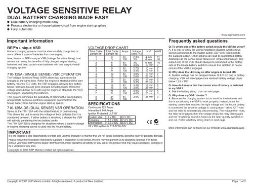
<strong>VOLTAGE</strong> <strong>SENSITIVE</strong> <strong>RELAY</strong><br />
DUAL BATTERY CHARGING MADE EASY<br />
Dual battery charging made easy<br />
Protects electronics on house battery circuit from engine start up spikes<br />
Fully automatic<br />
Important information<br />
<strong>BEP</strong>’s unique VSR<br />
Modern charging systems must be able to safely charge two or<br />
more different types of batteries from one engine.<br />
Now, thanks to <strong>BEP</strong>’s unique VSR (Voltage Sensitive Relay) boat<br />
owners can enjoy the benefits of fully charged engine starting<br />
batteries and deep cycle house batteries with one easy-to-install<br />
charging system.<br />
710-125A (SINGLE SENSE) VSR OPERATION<br />
The Voltage Sensitive Relay (VSR) allows two batteries to be<br />
charged at the same time. When the engine is started and the start<br />
battery reaches 13.7 volts, the VSR engages, allowing two battery<br />
banks (start and house) to be charged simultaneously. When the<br />
voltage drops below 12.8 volts (eg the engine is stopped), the VSR<br />
disengages, separating the batteries.<br />
This system eliminates the possibility of draining the wrong battery<br />
and protects sensitive electronic equipment powered from the<br />
house battery from harmful engine start up spikes.<br />
710-125A-DS (DUAL SENSE) VSR OPERATION<br />
Same as the 710-125A with the added feature of dual sensing.<br />
This allows the unit to sense the voltage of both batteries that it is<br />
connected between. If either battery is receiving a charge the VSR<br />
will activate paralleling the two battery banks.<br />
The 710-125A-DS is designed for situations where a battery charger<br />
or second charging source is used into the house battery.<br />
<strong>VOLTAGE</strong> DROP CHART<br />
Total Cable<br />
Length (m)<br />
1<br />
1<br />
2<br />
2<br />
3<br />
3<br />
4<br />
4<br />
5<br />
5<br />
6<br />
6<br />
7<br />
7<br />
8<br />
8<br />
Total Cable<br />
Length (ft)<br />
3<br />
3<br />
6<br />
6<br />
9<br />
9<br />
12<br />
12<br />
15<br />
15<br />
18<br />
18<br />
21<br />
21<br />
24<br />
24<br />
Amps<br />
50<br />
100<br />
50<br />
100<br />
50<br />
100<br />
50<br />
100<br />
50<br />
100<br />
50<br />
100<br />
50<br />
100<br />
50<br />
100<br />
SPECIFICATIONS<br />
Continuous 125 Amps<br />
Intermittent 140 Amps<br />
Ignition Protected UL1107<br />
System size 12 V DC 24 V DC<br />
Engages 13.7 V DC 27.4 V DC<br />
Disengages 12.8 V DC 25.6 V DC<br />
24 V DC system is 710-125A-24V<br />
Voltage<br />
Drop (%)<br />
mm² AWG<br />
2.3%<br />
3%<br />
4 mm<br />
6 mm<br />
11<br />
10<br />
3%<br />
3.5%<br />
6 mm<br />
10 mm 10<br />
7<br />
2.7%<br />
3.4%<br />
10 mm<br />
16 mm 7 5<br />
3.6%<br />
2.6%<br />
10 mm<br />
25 mm 7 3<br />
2.8%<br />
3.3%<br />
16 mm<br />
25 mm 5 3<br />
3.4%<br />
3.9%<br />
16 mm<br />
25 mm 5 3<br />
3.9%<br />
4.6%<br />
16 mm<br />
25 mm 5 3<br />
2.6% 25 mm 3<br />
IMPORTANT<br />
It is the installer’s sole responsibility to install and use this product in a manner that will not cause accidents, personal injury or property damage.<br />
Please follow the installation instructions supplied. If installation is not correct, the unit may not perform at its designed potential. If in doubt,<br />
consult your local <strong>BEP</strong> <strong>Marine</strong> dealer. <strong>BEP</strong> <strong>Marine</strong> Limited disclaims all liability for any use of this product that may cause accidents, damage or<br />
be a violation of any laws.<br />
Copyright © 2007 <strong>BEP</strong> <strong>Marine</strong> Limited. All rights reserved.<br />
Z168<br />
Frequently asked questions<br />
www.bepmarine.com<br />
Q: To which side of the battery switch should the VSR be wired?<br />
A: It is vital to follow the wiring installation diagram which shows<br />
correct connection to the master switch. <strong>BEP</strong> only recommends<br />
the supplied option. Other options can lead to accelerated battery<br />
discharge as the sense circuit draws 0.01 Amps continuously. The<br />
output wire of the VSR should always be connected to the battery<br />
side of the House battery switch to ensure true isolation of house<br />
circuits if the VSR is engaged.<br />
Q: Why does the LED stay on after engine is turned off?<br />
A: System voltage has not dropped below 12.8 V DC due to battery<br />
charging. VSR will disengage once residual battery voltage drops<br />
below 12.8 V DC.<br />
Q: How do I ensure that the correct size of battery is matched<br />
to my VSR?<br />
A: See the battery sizing chart on next page.<br />
Q: Why does my VSR ‘chatter’?<br />
A: Because the charging system is too small for the batteries and<br />
this is not allowing the VSR to work properly. Instead, once the<br />
starting battery has reached the right voltage and the house battery<br />
is connected the systems voltage is ‘caving down’ below 12.7 volts<br />
and the relay is automatically disconnecting. The voltage then rises,<br />
the relay re-engages; then the voltage drops the relay disengages<br />
and the ‘chattering’ sound is heard as the relay quickly switches in<br />
and out. Refer to battery sizing chart on next page.<br />
More information can be found on our Website www.bepmarine.com.<br />
Copyright © 2007 <strong>BEP</strong> <strong>Marine</strong> Limited. All rights reserved. A product of New Zealand. Page of 2
ENGINE<br />
BATTERY<br />
NAV LIGHTS<br />
POLE LIGHTS<br />
CABINLIGHTS<br />
COCKPIT LT<br />
BILGE PUMP<br />
SPARE<br />
ENGINE<br />
BATTERY<br />
NAV LIGHTS<br />
POLE LIGHTS<br />
CABINLIGHTS<br />
COCKPIT LT<br />
BILGE PUMP<br />
SPARE<br />
<strong>VOLTAGE</strong> <strong>SENSITIVE</strong> <strong>RELAY</strong><br />
DUAL BATTERY CHARGING MADE EASY<br />
Installation instructions<br />
BEFORE INSTALLING<br />
IMPORTANT<br />
Do not use any type of corrosion inhibiting spray such as CRC,<br />
INOX etc. on any part of this unit. These units are hermetically<br />
sealed so do not require any other form of sealing. The studs have<br />
been tinned to inhibit corrosion, use petroleum grease if required<br />
(on metal parts only).<br />
ENSURING CORRECT BATTERY SIZING:<br />
The charging system must be correctly sized to<br />
the batteries. If the charging system is too small for the batteries<br />
the VSR will not work properly.<br />
How the VSR works<br />
Once the starting battery’s voltage rises to above 13.7 VDC,<br />
the VSR switches to charge both batteries in parallel, when the<br />
voltage drops below 12.8 V DC the VSR disengages. A buzzerlike<br />
sound can be heard as the relay quickly switches in and out.<br />
Disengagement can occur at idle (low amps out due to slow speed<br />
of alternator) or if the house battery is at a low charge. An increase<br />
of the engine’s RPM will increase the alternator output and hold up<br />
the voltage.<br />
Alternator vs battery capacity<br />
Alternator Size Second battery size<br />
10 Amp 60 AH GRP 22<br />
16 Amp 85 AH GRP 24<br />
25-35 Amp 85-100 AH GRP 27<br />
50-60 Amp 100-130 AH GRP 31<br />
80-90 Amp 130-220 AH GRP 80<br />
INSTALLATION<br />
68 mm<br />
Connect the VSR to the back of the battery<br />
isolating switches, ensuring that the battery cable<br />
is correctly sized. This will ensure good current<br />
flow to the battery, reducing unwanted voltage<br />
drops to the VSR. The LED on the front of the<br />
VSR should be visible, as it will instantly show<br />
when it is in operation.<br />
Note: When using a VSR in conjunction with a high performance<br />
voltage regulator (eg Next Step Regulator) the regulator sense wire<br />
must go to the same point as the sense for the VSR ie the start battery.<br />
68 mm<br />
Remove base to expose studs and negative lead. Cut out cable<br />
access slots:<br />
1) With a hacksaw blade, cut vertical lines<br />
into the side walls of the VSR case, as shown<br />
by dashed lines (approximate positions). Stop<br />
cutting at the point where the plastic steps up<br />
Base (side view)<br />
to a thicker wall. Take care not to damage the<br />
circuit board with the blade.<br />
2) Once the two slots have been cut, with a pair of pliers bend the<br />
middle section (between the two slots) inwards until it snaps away<br />
from the main body (Along horizontal dashed lines)<br />
Use countersunk screws for<br />
fastening base down.<br />
Use Panhead screws for<br />
fastening the VSR onto the base.<br />
48 mm<br />
Wiring for Voltage Sensitive Relay<br />
VSR Rear view<br />
(same with both installations)<br />
Wiring for Dual Sensing Voltage Sensitive Relay<br />
701<br />
House Batt<br />
Isolator<br />
Panel<br />
Negative<br />
Bus Bar<br />
House Battery<br />
Isolator<br />
+<br />
701<br />
House Batt<br />
Isolator<br />
Panel<br />
Negative<br />
Bus Bar<br />
– House +<br />
Battery<br />
708-68.5<br />
Link Bars<br />
701<br />
Emergency<br />
Start<br />
Isolator<br />
708-68.5<br />
Link Bars<br />
Voltage<br />
Sensitive<br />
Relay<br />
Rear view<br />
SECOND BATTERY<br />
POSITIVE +<br />
SENSE BATTERY<br />
POSITIVE +<br />
Black 1 mm<br />
(Supplied)<br />
Battery<br />
Negative<br />
+<br />
708-68.5<br />
Link Bars<br />
701<br />
Emergency<br />
Start Isolator<br />
708-68.5<br />
Link Bars<br />
Dual Sensing<br />
Voltage Sensitive<br />
Relay<br />
– Start +<br />
Battery<br />
701<br />
Motor Batt<br />
Isolator<br />
Engine<br />
Motor Batt<br />
Isolator<br />
– Start +<br />
Battery<br />
701<br />
Motor Batt<br />
Isolator<br />
Engine<br />
Copyright © 2007 <strong>BEP</strong> <strong>Marine</strong> Limited. All rights reserved. A product of New Zealand. Page of 2