Auto trans diagnosis - BenzWorld.org
Auto trans diagnosis - BenzWorld.org
Auto trans diagnosis - BenzWorld.org

Create successful ePaper yourself
Turn your PDF publications into a flip-book with our unique Google optimized e-Paper software.
AUTO TRANS DIAGNOSIS - W4A020 & W4A040<br />
Article Text<br />
1994 Mercedes-Benz S320<br />
For 1<br />
Copyright © 1998 Mitchell Repair Information Company, LLC<br />
Thursday, November 20, 2008 02:08PM<br />
ARTICLE BEGINNING<br />
AUTOMATIC TRANSMISSIONS<br />
Mercedes-Benz W4A020 & W4A040<br />
APPLICATION & IDENTIFICATION<br />
Identification code is stamped on identification plate or<br />
<strong>trans</strong>mission housing. Use identification code when ordering parts.<br />
TRANSMISSION APPLICATIONS<br />
ÄÄÄÄÄÄÄÄÄÄÄÄÄÄÄÄÄÄÄÄÄÄÄÄÄÄÄÄÄÄÄÄÄÄÄÄÄÄÄÄÄÄÄÄÄ<br />
Year/Vehicle<br />
Trans.<br />
Application<br />
Model<br />
1983<br />
240D .............................. W4A020<br />
300 Series ........................ W4A040<br />
380 Series ........................ W4A040<br />
1984<br />
240D .............................. W4A020<br />
300 Series ........................ W4A040<br />
380 Series ........................ W4A040<br />
1985<br />
190 Series ........................ W4A020<br />
300 Series ........................ W4A040<br />
380 Series ........................ W4A040<br />
500 Series ........................ W4A040<br />
1986<br />
190 Series ........................ W4A020<br />
300 Series ........................ W4A040<br />
380 Series ........................ W4A040<br />
500 Series ........................ W4A040<br />
1987<br />
190 Series ........................ W4A020<br />
300 Series ........................ W4A040<br />
420 Series ........................ W4A040<br />
560 Series ........................ W4A040<br />
1988<br />
190D (2.5L & 2.5L TD) ............. W4A020<br />
190E (2.3L,<br />
2.3L-16V & 2.6L) ................. W4A020
260E (2.6L) ........................ W4A020<br />
300E .............................. W4A040<br />
300D .............................. W4A040<br />
300SDL ............................ W4A040<br />
300TD ............................. W4A040<br />
420SEL ............................ W4A040<br />
560SEC ............................ W4A040<br />
560SEL ............................ W4A040<br />
560SL ............................. W4A040<br />
1989<br />
190D (2.5L & 2.5L TD) ............. W4A020<br />
190E (2.3L,<br />
2.3L-16V & 2.6L) ................. W4A020<br />
260E (2.6L) ........................ W4A020<br />
300E .............................. W4A040<br />
300D .............................. W4A040<br />
300SDL ............................ W4A040<br />
300TD ............................. W4A040<br />
420SEL ............................ W4A040<br />
560SEC ............................ W4A040<br />
560SEL ............................ W4A040<br />
560SL ............................. W4A040<br />
1990<br />
190D (2.5L & 2.5L TD) ............. W4A020<br />
190E (2.3L,<br />
2.3L-16V & 2.6L) ................. W4A020<br />
260E (2.6L) ....................... W4A020<br />
300E .............................. W4A040<br />
300D .............................. W4A040<br />
300SDL ............................ W4A040<br />
300TD ............................. W4A040<br />
420SEL ............................ W4A040<br />
560SEC ............................ W4A040<br />
560SEL ............................ W4A040<br />
560SL ............................. W4A040<br />
1991<br />
190E (2.3L) ............... 722.408 W4A020<br />
190E (2.6L) ............... 722.409 W4A020<br />
300CE (3.0L) .............. 722.359 W4A040<br />
300D (2.5L Turbo) ......... 722.418 W4A020<br />
300E (2.6L) ............... 722.409 W4A020<br />
300E & 300TE (3.0L) ....... 722.358 W4A040<br />
300SE & 300SEL (3.0L) ..... 722.351 W4A040<br />
350SD &<br />
350SDL Turbo (3.5L) ..... 722.361 W4A040AUTO<br />
TRANS DIAGNOSIS - W4A020 & W
420SEL (4.2L) ............. 722.355 W4A040<br />
500SL (5.0L) .............. 722.353 W4A040<br />
560SEC & 560SEL (5.6L) .... 722.350 W4A040<br />
1992<br />
190E (2.3L) ............... 722.408 W4A020<br />
190E (2.6L) ............... 722.409 W4A020<br />
300CE (3.0L) .............. 722.359 W4A040<br />
300D (2.5L Turbo) ......... 722.418 W4A020<br />
300E (2.6L) ............... 722.409 W4A020<br />
300E & 300TE (3.0L) ....... 722.358 W4A040<br />
300SD Turbo (3.5L) ........ 722.367 W4A040<br />
300SE & 300SEL (3.2L) ..... 722.368 W4A040<br />
400E (4.2L) ............... 722.354 W4A040<br />
400SE (4.2L) .............. 722.366 W4A040<br />
500E (5.0L) ............... 722.365 W4A040<br />
500SEL (5.0L) ............. 722.370 W4A040<br />
1993<br />
190E (2.3L) ............... 722.408 W4A020<br />
190E (2.6L) ............... 722.409 W4A020<br />
300D (2.5L Turbo) ......... 722.418 W4A020<br />
300E (2.8L) ............... 722.433 W4A020<br />
300E (3.2L) ............... 722.369 W4A040<br />
300SD (3.5L) .............. 722.367 W4A040<br />
400E (4.2L) ............... 722.354 W4A040<br />
400SEL (4.2L) ............. 722.366 W4A040<br />
500E (5.0L) ............... 722.365 W4A040<br />
500SEL (5.0L) ............. 722.370 W4A040<br />
1994<br />
C220 (2.3L) ............... 722.423 W4A020<br />
C280 (2.8L) ............... 722.424 W4A020<br />
E320 (3.2L)<br />
Cabriolet ............... 722.369 W4A020<br />
Coupe ................... 722.369 W4A020<br />
Sedan ................... 722.369 W4A020<br />
Wagon ................... 722.369 W4A020<br />
E420 (4.2L) ............... 722.366 W4A020<br />
E500 (5.0L) ............... 722.370 W4A040<br />
S350 (3.5L) ............... 722.367 W4A040<br />
S420 (4.2L) ............... 722.366 W4A040<br />
S500 (5.0L) ............... 722.370 W4A040<br />
ÄÄÄÄÄÄÄÄÄÄÄÄÄÄÄÄÄÄÄÄÄÄÄÄÄÄÄÄÄÄÄÄÄÄÄÄÄÄÄÄÄÄÄÄÄ<br />
DESCRIPTION<br />
AUTO TRANS DIAGNOSIS - W4A020 & W
TRANSMISSION<br />
This is a fully automatic 4-speed <strong>trans</strong>mission consisting of<br />
a 3-element welded torque converter, 2 compound planetary gear sets, 2<br />
multiple-disc clutches, one overrunning clutch and 3 brake bands.<br />
Brake bands control function of planetary gear sets. A hydraulic<br />
system, pressurized by a primary gear type pump and a secondary piston<br />
type pump provide working pressure required to operate friction<br />
elements and automatic controls.<br />
1st Gear<br />
In 1st gear, brake band B-2 is applied and the one-way<br />
converter clutch is locked. In selector lever position "2", clutch K-2<br />
is also engaged. Both planetary gear sets are involved in gear<br />
reduction.<br />
2nd Gear<br />
In 2nd gear, brake band B-1 and brake band B-2 are applied.<br />
Both planetary gear sets are involved in gear reduction.<br />
3rd Gear<br />
In 3rd gear, brake band B-2 is applied and clutch K-1 is<br />
engaged. Only the rear planetary gear set is involved in gear<br />
reduction.<br />
4th Gear<br />
In 4th gear, clutch K-1 and clutch K-2 are applied. Both<br />
planetary gear sets rotate as a locked unit.<br />
Reverse Gear<br />
In reverse, disc brake B-3 is applied, the one-way converter<br />
clutch is locked, and clutch K-2 is engaged. Both planetary gear sets<br />
are involved in gear reduction.<br />
VALVE BODY<br />
The valve body receives inputs from selector lever position,<br />
mode selector switch, accelerator pedal position (control pressure),<br />
engine torque (intake manifold vacuum), kick-down and vehicle speed.<br />
Depending on operating conditions, the oil flow is controlled to<br />
various points of demand in the <strong>trans</strong>mission and the quality and<br />
pressure level are adapted to requirements.<br />
PRIMARY & SECONDARY PUMP<br />
Primary Pump<br />
The primary pump is housed in the front <strong>trans</strong>mission cover<br />
and AUTO is TRANS driven DIAGNOSIS by the - engine W4A020 through & W4A040Article the drive Text (p. flange 4)1994<br />
of<br />
Mercedes-Benz<br />
the torque<br />
S320For 1<br />
Copyrig
converter. The primary pump operates as long as the engine is turning,<br />
and supplies pressurized oil to the entire hydraulic system. The drive<br />
of the secondary pump is switched off by the cut-off piston by means<br />
of primary pump pressure.<br />
Secondary Pump<br />
The secondary pump is required only for towing and towstarting<br />
the vehicle. It is designed as an external gear pump and is<br />
positioned in the rear section of the <strong>trans</strong>mission. If needed, the<br />
secondary pump is driven by the centrifugal governor shaft. The<br />
secondary pump operates only if the engine is not running and the<br />
vehicle is rolling (tow-starting procedure), while brake band B-2<br />
slowly engages. Pump stops operating when vehicle comes to a stop or<br />
if <strong>trans</strong>mission has shifted into 4th gear (engine running).<br />
OPERATING PRESSURES<br />
The working pressure control valve, basic pressure control<br />
valve, 2 two-way check balls, a modulating pressure relief valve, and<br />
a non-return (one-way) valve and restriction form the working pressure<br />
circuit. The working pressure circuit is influenced by position of<br />
accelerator pedal, vehicle speed, selector lever position, and gear<br />
engaged.<br />
The working pressure, governed by working pressure circuit,<br />
operates disc brake B-3, brake bands and clutches. The pressure level<br />
is adapted to the particular operating condition, regardless of the<br />
quantity of oil supplied from the primary pump or secondary pump. This<br />
enables the primary pump capacity to be kept as low as possible and<br />
achieve a high <strong>trans</strong>mission efficiency.<br />
The working pressure is always the highest pressure in the<br />
hydraulic system. All other operating pressures are derived from this<br />
maximum pressure and reduced by control valves to a lower pressure<br />
level. The following governed pressures control the hydraulic system<br />
and operate shift element.<br />
* Reduced Operating Pressure<br />
* Governor Pressure<br />
* Lubricating Pressure<br />
* Modulating Pressure (Vacuum Controlled)<br />
* Modulating Pressure (Governor Controlled)<br />
* Full Throttle Pressure<br />
* Load Dependent Control Pressure<br />
* Kick-Down Control Pressure<br />
* Boosted Governor Pressure<br />
* Shift Pressure<br />
DAMPER SYSTEM<br />
AUTO TRANS
The principal task of the hydraulic system (circuits)<br />
consists of controlling the working pressure during gear changes<br />
(shifts). During each gear shift <strong>trans</strong>ition, the engine speed<br />
increases (during a downshift) or decreases (during an upshift). In<br />
order to provide a smooth <strong>trans</strong>ition between gear shifts, 4<br />
independent damper circuits are used.<br />
The clutch K-1 damper circuit controls clutch K-1 during 2nd<br />
to 3rd gear downshifts or upshifts. The clutch K-2 damper circuit<br />
controls clutch K-2 during 3rd to 4th gear downshifts or upshifts. The<br />
brake band B-1 damper circuit controls brake band B-1 during 1st to<br />
2nd gear downshifts or upshifts.<br />
The "engaging" damper circuit controls the engagement of the<br />
clutches or brake bands, depending on selector lever position. When<br />
selector lever is moved from "N" (Neutral) to "D" (Drive) or "3" (3rd<br />
gear), brake bands B-1 and B-2 are controlled. When selector lever is<br />
moved from "N" (Neutral) to "2" (2nd gear), clutch K-2 and brake band<br />
B-2 are controlled. When selector lever is moved from "N" (Neutral) to<br />
"R" (Reverse), clutch K-2 and disc brake B-3 are controlled.<br />
The"engaging" damper controls the working pressure pattern after drive<br />
positions "R", "D", "3" and "2" are engaged.<br />
TRANSMISSION SHIFT POINT DELAY<br />
The 2nd to 3rd gear upshift on some models is delayed 60-80<br />
seconds to enable the catalytic converter to more rapidly reach its<br />
operating temperature. The shift point retard solenoid is energized by<br />
the CIS-E control unit or air mass sensor control unit through the<br />
<strong>trans</strong>mission shift point (upshift) retard relay.<br />
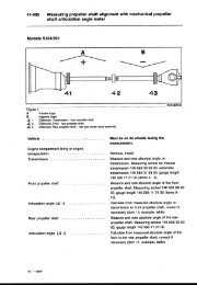
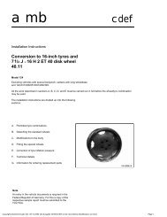
Governor pressure is lowered through hydraulic line which is<br />
bolted to the governor pressure test port. See Fig. 1. Under certain<br />
operating conditions (coolant temperature, vehicle speed and time),<br />
the solenoid valve is de-energized and the governor pressure is<br />
dumped. The 2nd to 3rd gear upshift is delayed only when coolant<br />
temperature is 0-140øF (0-60øC). The operating time is dependent on<br />
coolant temperature when the engine is started, and is longest when<br />
coolant temperature is 68-86øF (20-30øC).<br />
AUTO TRANS DIAGNOSIS - W4A020 & W4A040Article Text (p. 6)1994 Mercedes-Benz S320For 1<br />
Copyrig
Fig. 1: Transmission Shift Point Delay Components (190E 2.3L Shown)<br />
Courtesy of Mercedes-Benz of North America.<br />
TROUBLE SHOOTING<br />
Transmission Slips In All Gears<br />
Incorrect modulating pressure. Modulating pressure control<br />
valve or pressure relief valve is dirty or sticking. Vacuum line to<br />
<strong>trans</strong>mission vacuum capsule clogged or leaking. Working pressure<br />
control valve dirty or sticking. Low working pressure. Defective<br />
primary pump.<br />
Transmission Slips When Starting Off In 1st Or 2nd<br />
(Reverse Works Normally)<br />
Band B-2 shift valve sticking. Band B-2 piston worn or<br />
damaged. Band B-2 adjusted incorrectly or worn or damaged. Adjust<br />
AUTO TRANS DIAGNOSIS - W4A020 & W4A040Article Text (p. 7)1994 Mercedes-Benz S320For 1<br />
brake Band B-2 by installing a longer thrust pin (if necessary). If<br />
<strong>trans</strong>mission operates properly with selector lever in "2", but not in<br />
"3" or "D" position, the one-way clutch may be slipping.<br />
Copyrig<br />
Transmission Slips In 2nd Gear Or Shifts From 1st To 3rd Gear<br />
Check control valve B-1 for ease of operation. Replace valve<br />
body (if necessary). Remove and install brake band piston B-1, check<br />
sealing ring and replace (if necessary). Replace brake band B-1 and<br />
thrust body for B-1. Command valve binding.<br />
Transmission Slips During 2-3 Upshift Or Slips Initially,
Then Grabs Hold<br />
Check modulating pressure and adjust (if necessary). Check<br />
for temperature throttle installation (if equipped). Valve body worn<br />
or damaged. Replace valve body (if necessary). Replace inner plates of<br />
clutch K-1 or recondition clutch (if necessary). Check Teflon ring of<br />
front cover.<br />
Transmission Slips During 3-4 Upshift<br />
Check and adjust modulating pressure. Governor damaged or<br />
working pressure incorrect. Valve body worn or damaged. Replace valve<br />
body (if necessary) Check Teflon rings supporting clutch K-2. Replace<br />
inner plates of clutch K-2 or recondition clutch (if necessary).<br />
No Positive Engagement In Reverse<br />
Check plates and sealing rings on disc brake B-3 piston.<br />
Replace if necessary.<br />
Harsh Engagement When Shifting Gears<br />
Incorrect working pressure. Check and adjust modulating<br />
pressure. Check vacuum line and connections for leaks. On diesel<br />
engine equipped vehicles, check vacuum control valve. Coolant entering<br />
<strong>trans</strong>mission oil cooler and contamination <strong>trans</strong>mission fluid. Replace<br />
radiator. If necessary, replace all friction linings and/or replace<br />
<strong>trans</strong>mission.<br />
Harsh Engagement When Selecting "D" Or "R"<br />
Idle speed too high. Check pressure receiving (pick-up)<br />
piston in valve body for ease of operation and correct installation.<br />
Replace valve body (if necessary).<br />
NOTE:<br />
Pressure pick-up requires a running period of approximately<br />
2 seconds. Harsh engagement may occur during repeated shifts<br />
between "N" and "D". If harshness takes place within 2<br />
seconds, condition is considered normal.<br />
Harshness On 4-3 Downshift<br />
Sealing ring on release end of band B-2 worn or damaged. Band<br />
B-2 piston worn or damaged. Band B-2 thrust body damaged.<br />
body.<br />
Chatter During Upshift<br />
If upshift is not in proper order, repair or replace valve<br />
Will Not Upshift<br />
Incorrect governor pressure. Defective governor assembly.<br />
Check kickdown solenoid valve for a tendency to stick or for constant<br />
voltage to solenoid caused by a defective fuel pump relay or sticking<br />
AUTO TRANS<br />
kickdown switch. Valve body dirty or valves sticking. Repair or
eplace valve body.<br />
Upshifts At Higher Speeds Than Specified<br />
Check pressure control cable engagement, condition and<br />
adjustment. Check kickdown solenoid valve for a tendency to stick or<br />
for constant voltage to solenoid caused by a defective fuel pump relay<br />
or sticking kickdown switch. Check governor pressure. If regulator<br />
pressure is too low, replace centrifugal governor. Ensure control<br />
pressure regulating valve is operable.<br />
Upshifts At Lower Speeds Than Specified<br />
Check pressure control cable engagement, condition and<br />
adjustment. Check full throttle stop by accelerating engine and<br />
ensuring that throttle valve rests against full throttle stop.<br />
Readjust throttle stop (if necessary). Check governor pressure. If<br />
governor pressure is too high, replace centrifugal governor. Repair or<br />
replace valve body.<br />
No Kickdown<br />
Check throttle control and pressure control cable engagement,<br />
condition and adjustment. Connect kickdown solenoid to battery and<br />
check for proper operation. Replace solenoid (if necessary). Check<br />
kickdown valve in valve body. Replace valve body (if necessary).<br />
No Downshift (4-3 & 3-2)<br />
Control pressure cable out of adjustment. Leaking vacuum<br />
hoses and/or connections. Ensure brake shaft piston is operable.<br />
Replace valve body (if necessary).<br />
Uncontrolled Downshifts Outside Range Of Kickdown Switch<br />
Remove kickdown solenoid valve. Check "O" ring on kickdown<br />
solenoid valve for damage. Check kickdown switch for sticking in<br />
pushed-in position. Replace switch (if necessary). Check for kickdown<br />
solenoid valve stuck in opened position. Replace kickdown solenoid<br />
valve (if necessary).<br />
Poor Acceleration When Starting Off<br />
Check stall speed. If stall speed is 400-700 RPM less than<br />
specified value, one-way clutch in torque converter is slipping.<br />
Replace torque converter (if necessary).<br />
Parking Lock Will Not Engage<br />
Check rear engine mount. Replace engine mount (if necessary).<br />
Check adjustment of selector rod. Adjust selector rod (if necessary).<br />
Selector Lever Cannot Engage "R" Or "P"<br />
With engine running, clean centrifugal governor and ensure<br />
correct operation. With engine not running, check operation of detent AUTO TRANS DIA
piston in lower cover.<br />
Engine Cannot Be Started In Selector Lever Position "P" & "N"<br />
Adjust shift rod and starter lock-out switch. Replace starter<br />
lock-out switch (if necessary).<br />
Oil Loss With Smoke In Exhaust<br />
Diaphragm in vacuum control unit defective. Transmission oil<br />
is being drawn from engine through vacuum line. Replace vacuum control<br />
unit (if necessary).<br />
Oil Loss Between Torque Converter & Primary Pump<br />
Seal torque converter oil drain plug. If leak continues,<br />
replace radial sealing ring and "O" ring on primary pump. Check<br />
primary pump "O" ring groove for porosity. Replace primary pump (if<br />
necessary).<br />
Howling Noise When Changing Gears (Under Full Load)<br />
Replace <strong>trans</strong>mission oil filter.<br />
Howling Noise Which Increases As Engine RPM Increases<br />
Check primary pump and replace if necessary.<br />
1st Gear & Reverse Too Loud<br />
Replace front planetary gear set. Reverse and 1st gear are<br />
louder than forward (driving) gears due to gear reduction. If noise<br />
seems too loud, or if in doubt, a similar vehicle should be used for<br />
comparison.<br />
3rd Gear Too Loud<br />
Replace rear planetary gear set.<br />
Rattling Noise at 1500 RPM In All Selector Lever Positions<br />
Except "R"<br />
Disc brake B-3 plates are vibrating in <strong>trans</strong>mission housing.<br />
Replace plates of disc brake B-3, install damper spring and set<br />
release clearance to minimum value.<br />
Light Grinding Noise In "P" & "N" Selector Lever Positions<br />
This condition is normal if a "rolling" noise of front<br />
planetary gear set is heard. If noise seems too loud, or if in doubt,<br />
a similar vehicle should be used for comparison.<br />
"Rolling" Noises When Driving In Reverse<br />
Disc brake B-3 release clearance too great. Adjust release<br />
clearance to 0.06-0.08" (1.5-2.0 mm) or replace disc brake plates.<br />
Outside plate carrier of clutch K-1 contacts piston.<br />
AUTO TR
place.<br />
Primary Pump Bushing Loosens After A Short Operating Period<br />
Dowel pins for centering <strong>trans</strong>mission to engine are not in<br />
TESTING<br />
For vacuum control circuit tests, hydraulic pressure tests,<br />
and road tests, see the AUTO TRANS OVERHAUL - W4A020 & W4A040 article<br />
in the AUTO TRANS OVERHAUL section.<br />
END OF ARTICLE<br />
AUTO TRANS DIAGNOSIS - W4A020 & W4A040Article Text (p. 11)1994 Mercedes-Benz S320For 1<br />
Copy
TRANSMISSION REMOVAL & INSTALLATION - A/T<br />
Article Text<br />
1994 Mercedes-Benz S320<br />
For 1<br />
Copyright © 1998 Mitchell Repair Information Company, LLC<br />
Thursday, November 20, 2008 02:11PM<br />
ARTICLE BEGINNING<br />
1994 TRANSMISSION SERVICING<br />
Mercedes-Benz Transmission Removal & Installation - <strong>Auto</strong>matic<br />
S320, S350, S420, S500<br />
REMOVAL & INSTALLATION<br />
CAUTION: If metal chips are present in <strong>trans</strong>mission oil pan, torque<br />
converter must be replaced. Flushing will not remove all<br />
metal chips from a torque converter. Failure to replace<br />
torque converter may result in future <strong>trans</strong>mission failure.<br />
S350, S420 & S500<br />
Removal<br />
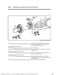
1) Disconnect negative battery cable. Disconnect longitudinal<br />
engine throttle control shaft. Disconnect control pressure cable.<br />
Remove front crossmember assembly.<br />
2) Remove <strong>trans</strong>mission oil pan drain plug. Remove torque<br />
converter drain plug. Drain <strong>trans</strong>mission fluid. Remove starter. Remove<br />
torque converter drive plate bolts (6 bolts) through starter opening.<br />
Remove entire exhaust system assembly from exhaust manifold(s). Remove<br />
rear crossmember with mount.<br />
3) Release cable strap and unscrew cable on kickdown solenoid<br />
valve. Unscrew retaining bolts for pulse generator. Remove pulse<br />
generator. On V8 engines, disconnect shift point retard connector<br />
located on right rear corner of engine.<br />
4) On all models, loosen drive shaft center bearing bolts.<br />
Loosen large clamping nut on drive shaft. Clamping nut is located near<br />
center bearing. Remove drive shaft flange bolts. With clamping nut<br />
loosened, push drive shaft as far back from <strong>trans</strong>mission as possible.<br />
5) Turn starter lockout switch locking element before<br />
disconnecting starter lockout switch connector. Using 2 screwdrivers,<br />
pry off starter lockout switch connector from <strong>trans</strong>mission.<br />
6) Disconnect shift rod from range selector lever. Disconnect<br />
White vacuum line for vacuum box. Disconnect Red vacuum line for mode<br />
program. Disconnect Black/Green vacuum line for shift point retard.<br />
7) Disconnect <strong>trans</strong>mission oil cooler feed and return lines.<br />
Remove <strong>trans</strong>mission dipstick tube bolt from <strong>trans</strong>mission and cylinder<br />
head. Remove <strong>trans</strong>mission dipstick tube.<br />
8) On V8 engines, remove <strong>trans</strong>mission mounting bolts except 2<br />
nuts on either side of <strong>trans</strong>mission. Using a <strong>trans</strong>mission jack, lift<br />
<strong>trans</strong>mission slightly. Remove 2 remaining <strong>trans</strong>mission mounting nuts.<br />
9) On 6-cylinder engines, remove <strong>trans</strong>mission mounting bolts<br />
except 2 bolts on either side of <strong>trans</strong>mission. Using a <strong>trans</strong>mission
jack, lift <strong>trans</strong>mission slightly. Remove 2 remaining <strong>trans</strong>mission<br />
mounting bolts. On all vehicles, push <strong>trans</strong>mission rearward and lower.<br />
Ensure torque converter does not fall from <strong>trans</strong>mission during<br />
removal.<br />
Installation<br />
To install, reverse removal procedure. Tighten bolts and nuts<br />
to specification. See TORQUE SPECIFICATIONS. Use NEW <strong>trans</strong>mission oil<br />
cooler feed and return line "O" rings. Adjust control pressure cable<br />
and linkages as necessary. Fill <strong>trans</strong>mission with fluid. See<br />
TRANSMISSION SERVICING - A/T article in AUTOMATIC TRANSMISSION<br />
SERVICING section.<br />
S320<br />
Removal<br />
1) Disconnect negative battery cable. Remove <strong>trans</strong>mission<br />
dipstick tube bolt from <strong>trans</strong>mission and cylinder head. Using pliers,<br />
squeeze plastic clip together and pull out control pressure cable.<br />
2) Remove <strong>trans</strong>mission oil pan drain plug. Remove torque<br />
converter drain plug. Drain <strong>trans</strong>mission fluid. Remove plastic cover<br />
to access torque converter drive plate bolts. Remove torque converter<br />
drive plate bolts (6 bolts) through opening.<br />
3) Remove crossmember with mount. Remove drive shaft flange<br />
bolts. Disconnect oxygen sensor harness on tunnel and disconnect<br />
mounting clips. Remove exhaust support bracket bolts from<br />
<strong>trans</strong>mission. Remove entire exhaust system assembly from exhaust<br />
manifold.<br />
4) Remove speedometer shaft. On vehicles equipped with an<br />
electronic speedometer, unscrew pulse generator. On all vehicles,<br />
disconnect shift point increase solenoid valve connector. Disconnect<br />
<strong>trans</strong>mission overload switch connector and pull off vacuum line.<br />
5) Turn starter lockout switch locking element before<br />
disconnecting starter lockout switch connector. Using 2 screwdrivers,<br />
pry off starter lockout switch connector from <strong>trans</strong>mission.<br />
6) Disconnect shift rod from range selector lever. Disconnect<br />
<strong>trans</strong>mission oil cooler feed and return lines. Remove <strong>trans</strong>mission<br />
dipstick tube bolt from <strong>trans</strong>mission. Remove <strong>trans</strong>mission dipstick<br />
tube. Ensure all electrical connections are disconnected from<br />
<strong>trans</strong>mission.<br />
7) Install Retainer (126 589 01 62 00) through ventilation<br />
grill cutout into torque converter drain plug. Remove <strong>trans</strong>mission<br />
mounting bolts except 2 bolts on either side of <strong>trans</strong>mission. Using a<br />
<strong>trans</strong>mission jack, lift <strong>trans</strong>mission slightly. Remove 2 remaining<br />
<strong>trans</strong>mission mounting bolts. Push <strong>trans</strong>mission rearward and lower.<br />
Installation<br />
To install, reverse removal procedure. When installing torque TRANSMISS
converter to <strong>trans</strong>mission, apply a light coat of grease to torque<br />
converter centering pin. Tighten bolts and nuts to specification. See<br />
TORQUE SPECIFICATIONS. Adjust control pressure cable and linkages as<br />
necessary. Fill <strong>trans</strong>mission with fluid. See appropriate<br />
TRANSMISSION SERVICING - A/T article in AUTOMATIC TRANSMISSION<br />
SERVICING section.<br />
TORQUE SPECIFICATIONS<br />
TORQUE SPECIFICATIONS TABLE<br />
ÄÄÄÄÄÄÄÄÄÄÄÄÄÄÄÄÄÄÄÄÄÄÄÄÄÄÄÄÄÄÄÄÄÄÄÄÄÄÄÄÄÄÄÄÄÄÄÄÄÄÄÄÄÄÄÄÄÄÄÄ<br />
Application<br />
Ft. Lbs. (N.m)<br />
Drive Plate Bolt ................................. 31 (42)<br />
Front Crossmember Bolt (1) ....................... 33 (45)<br />
Drive Shaft Clamping Nut ................... 22-30 (30-40)<br />
Transmission Mounting Bolt (2)<br />
10-mm .......................................... 41 (55)<br />
12-mm .......................................... 48 (65)<br />
Transmission Oil Pan Drain Plug .................. 10 (14)<br />
Torque Converter Drain Bolt ...................... 12 (16)<br />
(1) - Replace self-locking bolts.<br />
(2) - V8 engines use 2 nuts, one on each side of<br />
<strong>trans</strong>mission.<br />
ÄÄÄÄÄÄÄÄÄÄÄÄÄÄÄÄÄÄÄÄÄÄÄÄÄÄÄÄÄÄÄÄÄÄÄÄÄÄÄÄÄÄÄÄÄÄÄÄÄÄÄÄÄÄÄÄÄÄÄÄ<br />
END OF ARTICLE<br />
TRANSM
TRANSMISSION SERVICING - A/T<br />
Article Text<br />
1994 Mercedes-Benz S320<br />
For 1<br />
Copyright © 1998 Mitchell Repair Information Company, LLC<br />
Thursday, November 20, 2008 02:12PM<br />
ARTICLE BEGINNING<br />
1994 TRANSMISSION SERVICING<br />
Mercedes-Benz Transmission Servicing - <strong>Auto</strong>matic<br />
S320, S350, S420, S500<br />
IDENTIFICATION<br />
AUTOMATIC TRANSMISSION APPLICATIONS TABLE<br />
ÄÄÄÄÄÄÄÄÄÄÄÄÄÄÄÄÄÄÄÄÄÄÄÄÄÄÄÄÄÄÄÄÄÄÄÄÄÄÄÄÄÄÄÄÄÄÄÄÄÄÄÄÄÄÄÄÄÄÄÄÄÄÄÄÄÄÄÄÄÄ<br />
Model Body Transmission<br />
S320 3.2L ................... 140.032 .................... 722.508<br />
S350 3.5L ................... 140.043 .................... 722.367<br />
S420 4.2L ................... 140.043 .................... 722.366<br />
S500 5.0L ................... 140.051 .................... 722.370<br />
ÄÄÄÄÄÄÄÄÄÄÄÄÄÄÄÄÄÄÄÄÄÄÄÄÄÄÄÄÄÄÄÄÄÄÄÄÄÄÄÄÄÄÄÄÄÄÄÄÄÄÄÄÄÄÄÄÄÄÄÄÄÄÄÄÄÄÄÄÄÄ<br />
LUBRICATION<br />
SERVICE INTERVALS<br />
Check fluid level at first 800-1000 miles and every 15,000<br />
miles afterward. Change fluid and filter every 30,000 miles. Under<br />
severe service conditions, change fluid every 15,000 miles.<br />
CHECKING FLUID LEVEL<br />
With <strong>trans</strong>mission fluid at normal operating temperature of<br />
176øF (80øC), park vehicle on level surface. Place selector lever in<br />
the "P" position and set parking brake. Allow engine to idle for 2<br />
minutes. Measure fluid level with dipstick completely inserted and<br />
locking lever released.<br />
RECOMMENDED FLUID<br />
Use Dexron-II ATF.<br />
FLUID CAPACITIES<br />
TRANSMISSION REFILL CAPACITIES TABLE<br />
ÄÄÄÄÄÄÄÄÄÄÄÄÄÄÄÄÄÄÄÄÄÄÄÄÄÄÄÄÄÄÄÄÄÄÄÄÄÄÄÄÄÄÄÄÄÄÄÄÄÄÄÄÄÄÄÄÄÄÄÄÄÄÄÄÄÄÄÄÄÄ<br />
Refill<br />
Dry Fill<br />
Application Qts. (L) Qts. (L)<br />
S320 & S350 ................ 6.6 (6.2) ................. 7.7 (7.3)
S420 & S500 ................ 8.1 (7.7) ................. 9.1 (8.6)<br />
ÄÄÄÄÄÄÄÄÄÄÄÄÄÄÄÄÄÄÄÄÄÄÄÄÄÄÄÄÄÄÄÄÄÄÄÄÄÄÄÄÄÄÄÄÄÄÄÄÄÄÄÄÄÄÄÄÄÄÄÄÄÄÄÄÄÄÄÄÄÄ<br />
DRAINING & REFILLING<br />
1) Disconnect filler tube from oil pan, and drain fluid.<br />
Rotate engine until torque converter drain plug is at bottom of torque<br />
converter housing. Remove plug and drain fluid. Install plug, using a<br />
new sealing ring. Remove oil pan and filter.<br />
2) Install filter and oil pan, using a new gasket. Attach<br />
fill tube, using new sealing rings on hollow screw. Add about 3.2 qts.<br />
(3L) of automatic <strong>trans</strong>mission fluid.<br />
3) Apply parking brake and start engine. Place selector lever<br />
in the "P" position. Run engine at idle and gradually add fluid.<br />
Momentarily place selector lever in each gear, and then return to "P"<br />
position. Check fluid level and add if necessary. DO NOT overfill.<br />
ADJUSTMENTS<br />
SHIFT LINKAGE<br />
Before adjusting shift linkage, make sure neutral safety<br />
switch is properly adjusted. See NEUTRAL SAFETY SWITCH. To adjust<br />
shift linkage, disconnect control rod from gear selector lever. Place<br />
<strong>trans</strong>mission lever in "N" (Neutral) position. Loosen lock nut at end<br />
of control rod. Adjust rod length so clearance is .04" (1 mm) between<br />
gear selector lever and "N" stop on gate plate. Connect control rod,<br />
and secure and tighten lock nut. See Fig. 1.<br />
Fig. 1: Adjusting Shift Linkage (722.4 Trans. Shown; Others Similar)<br />
Courtesy of Mercedes-Benz of North America<br />
CONTROL PRESSURE CABLE<br />
S350<br />
TRANSM
Ensure throttle control cable is correctly adjusted.<br />
Disconnect cable ball socket. Pull control cable forward until slight<br />
resistance is felt. Holding cable in this position, check if ball<br />
socket fits on ball with no tension. If tension is felt, use adjusting<br />
nut to change cable length.<br />
S320<br />
Remove air cleaner. Adjust control pressure cable by turning<br />
adjusting screw until tips of needles align. Install air cleaner. See<br />
Fig. 2.<br />
Fig. 2: Aligning Needles (S320)<br />
Courtesy of Mercedes-Benz of North America<br />
S420 & S500<br />
Remove air cleaner. Loosen 2 nuts on connecting rod. Turn<br />
connecting rod until tips of needles align. See Fig. 3. Tighten 2 nuts<br />
on connecting rod. Install air cleaner.<br />
TRANSMISSION SERVICING - A/TArticle Text (p. 3)1994 Mercedes-Benz S320For 1<br />
Co
Fig. 3: Aligning Needles (V8 Engine)<br />
Courtesy of Mercedes-Benz of North America<br />
CONTROL PRESSURE CABLE VACUUM ELEMENT<br />
NOTE:<br />
Not all vehicles are equipped with a control pressure cable<br />
vacuum element. Only vehicles with dual shifting modes for<br />
<strong>trans</strong>mission may have this option.<br />
1) Ensure control pressure cable is properly adjusted. See<br />
CONTROL PRESSURE CABLE. Raise and support vehicle. Disconnect vacuum<br />
hose from control pressure cable vacuum element. See Fig. 4.<br />
2) Connect a vacuum supply to vacuum element. Pull control<br />
pressure cable up to full load stop. Measure how far piston sticks out<br />
of vacuum element (distance "A"). See Fig. 5. See VACUUM ELEMENT<br />
PISTON PROTRUSION table. If vacuum element piston protrusion is not to<br />
TRANSMISSION specification, SERVICING turn adjustment - A/TArticle screw Text (p. on 4)1994 control Mercedes-Benz pressure S320For cable 1 vacuum<br />
element. See Fig. 4.<br />
Copyright © 1998 Mitchell R
Fig. 4: Connecting Vac. Hose To Control Pressure Cable Vac. Element<br />
Courtesy of Mercedes-Benz of North America<br />
VACUUM ELEMENT PISTON PROTRUSION TABLE<br />
ÄÄÄÄÄÄÄÄÄÄÄÄÄÄÄÄÄÄÄÄÄÄÄÄÄÄÄÄÄÄÄÄÄÄÄÄÄÄÄÄÄÄÄÄÄÄÄÄÄÄÄÄÄÄÄÄÄÄÄÄÄÄÄÄÄÄÄÄÄÄ<br />
Application<br />
In. (mm)<br />
6-Cyl. Engine<br />
With 722.3 Transmission (1) .............................. .28 (7)<br />
With 722.4 Transmission (1) .............................. .24 (6)<br />
8-Cyl. Engine .............................................. .24 (6)<br />
(1) - See IDENTIFICATION for <strong>trans</strong>mission application.<br />
ÄÄÄÄÄÄÄÄÄÄÄÄÄÄÄÄÄÄÄÄÄÄÄÄÄÄÄÄÄÄÄÄÄÄÄÄÄÄÄÄÄÄÄÄÄÄÄÄÄÄÄÄÄÄÄÄÄÄÄÄÄÄÄÄÄÄÄÄÄÄ<br />
TRANSMISSION SERVICING - A/TArticle Text (p. 5)1994 Mercedes-Benz S320For 1<br />
Copyright © 1998 Mitchell R
Fig. 5: Checking Vacuum Element Piston Protrusion<br />
Courtesy of Mercedes-Benz of North America<br />
NEUTRAL SAFETY SWITCH<br />
1) Neutral safety switch is located behind <strong>trans</strong>mission<br />
selector lever on <strong>trans</strong>mission. Loosen neutral safety switch attaching<br />
screws. Ensure <strong>trans</strong>mission selector lever is in "N" position.<br />
2) Insert a 5/32" (4 mm) drill bit through select lever<br />
adjustment hole and into neutral safety switch housing. Tighten screws<br />
and remove drill bit. Ensure vehicle starts in "P" and "N" positions<br />
only. See Fig. 1.<br />
SHIFT POINT RETARD UNIT<br />
NOTE: Not all vehicles are equipped with shift point retard.<br />
TRANSMISSION SERVICING - A/TArticle Text (p. 6)1994 Mercedes-Benz S320For 1<br />
1) If shift point retard unit is being replaced, ensure<br />
distances "A" and "B" are <strong>trans</strong>ferred to replacement unit. See Fig. 6.<br />
To check shift point retard, drive vehicle in "D" range with light<br />
throttle pressure from a stop.<br />
2) If shift point retard is functioning properly, vehicle<br />
will start moving in second gear and 2-3 shift will occur above 30<br />
MPH. If vehicle starts in first gear, shift point retard is too high.<br />
To lower shift point retard, turn adjustment screw to the right. See<br />
Fig. 6.<br />
3) If vehicle 2-3 shift occurs at less than 30 MPH, shift<br />
point retard is too low. To raise shift point retard, turn adjustment<br />
Copyright © 1998 Mitchell R
screw to the left. See Fig. 6.<br />
Fig. 6: Identifying Shift Point Retard Adjustment Screw<br />
Courtesy of Mercedes-Benz of North America<br />
END OF ARTICLE<br />
TRANSM
FIXTURE FOR B-1 PISTON R & I - AUTO TRANS.722.3/4/5<br />
Article Text<br />
1994 Mercedes-Benz S320<br />
For 1<br />
Copyright © 1998 Mitchell Repair Information Company, LLC<br />
Thursday, November 20, 2008 02:13PM<br />
ARTICLE BEGINNING<br />
TECHNICAL SERVICE BULLETIN<br />
AUTOMATIC TRANSMISSIONS 722.3/4/5<br />
FIXTURE FOR B-1 PISTON REMOVAL AND INSTALLATION<br />
Model(s): All Mercedes-Benz Models With <strong>Auto</strong>. Trans. 722.3/4/5<br />
Group:<br />
27 - <strong>Auto</strong>matic Transmission<br />
Bulletin No.: MBNA 27/31, 58/84<br />
Date: August 1995<br />
SERVICE INFORMATION<br />
A new special tool has been developed for the removal and<br />
installation of automatic <strong>trans</strong>mission piston B-1 with the<br />
<strong>trans</strong>mission installed in the vehicle.<br />
SPECIAL TOOL INFORMATION TABLE<br />
ÄÄÄÄÄÄÄÄÄÄÄÄÄÄÄÄÄÂÄÄÄÄÄÄÄÄÄÄÄÄÄÄÄÄÄÄÄÄÄÄÄÄÄÄÄÄÄÄÄÄÂÄÄÄÄÄÄÄÄÄÄÄÄÄÄÄÄ<br />
Part Number ³ Description ³ Group/Category<br />
ÄÄÄÄÄÄÄÄÄÄÄÄÄÄÄÄÄÅÄÄÄÄÄÄÄÄÄÄÄÄÄÄÄÄÄÄÄÄÄÄÄÄÄÄÄÄÄÄÄÄÅÄÄÄÄÄÄÄÄÄÄÄÄÄÄÄÄ<br />
900 589 27 23 00 ³ Fixture for B-1 piston removal ³ 27/B<br />
³ and installation See Fig. 1. ³<br />
ÄÄÄÄÄÄÄÄÄÄÄÄÄÄÄÄÄÁÄÄÄÄÄÄÄÄÄÄÄÄÄÄÄÄÄÄÄÄÄÄÄÄÄÄÄÄÄÄÄÄÁÄÄÄÄÄÄÄÄÄÄÄÄÄÄÄÄ<br />
WORK INSTRUCTIONS FOR USE OF B-1 PISTON SPECIAL TOOL<br />
1. Remove <strong>trans</strong>mission oil pan and gasket, oil filter, valve body and<br />
large intermediate plate. See Fig. 2. (SMS Job Nos. 27-400 and<br />
27-430).<br />
2. Loosen closing cover of reaction valve B-1 (33) or overload<br />
protection switch S65 (33b) by approx. 3 - 4 turns. See Fig. 3.<br />
* Tightening torque: 70 N.m.<br />
3. Install special tool angled bracket to <strong>trans</strong>mission housing using<br />
three 8 mm hex bolts. See Fig. 4.<br />
* Tightening torque: 13 N.m.<br />
4. Mount special tool compressing lever to angled bracket at side<br />
mounting eyelet that serves as pivot point. See Fig. 5.<br />
5. Pull special tool compressing lever outward, in direction of
lower arrow to press in cover of piston B-1 allowing removal of<br />
circlip. See Fig. 6.<br />
6. Carefully release compressing lever inward, in direction of lower<br />
arrow to remove piston B-1 from <strong>trans</strong>mission housing. See Fig. 7.<br />
7. Reassemble in reverse order.<br />
CAUTION: During reassembly, always observe critical attention to<br />
correct installation position of B-1 piston return springs<br />
and alignment of B-1 piston pin into band 1 socket.<br />
NOTE: An administrative message will be issued in the near future<br />
regarding time allowance.<br />
Fig. 1: B-1 Piston Removal Fixture<br />
FIXTURE FOR B
FIXTURE FOR B-1 PISTON R & I - AUTO TRANS.722.3/4/5Article Text (p. 3)1994 Mercedes-Benz S320F<br />
Fig. 2: Oil Pan & Valve Body Removal
Fig. 3: Reaction Valve & Overload Protection Switch<br />
Fig. 4: Installing Angled Bracket<br />
FIXTURE FOR B-1 PISTON R & I - AUTO TRANS.722.3/4/5Article Text (p. 4)1994 Mercedes-Benz S320F
Fig. 5: Mounting Compressing Lever<br />
FIXTURE FOR B-1 PISTON R & I - AUTO TRANS.722.3/4/5Article Text (p. 5)1994 Mercedes-Benz S320F<br />
Fig. 6: Compressing B-1 Piston Cover
Fig. 7: Removing B-1 Piston<br />
END OF ARTICLE<br />
FIXTURE FOR B-1 PISTON R & I - AUTO TRANS.722.3/4/5Article Text (p. 6)1994 Mercedes-Benz S320F
722.3/4/5 - SEALING PLUGS FOR VACUUM ACTUATORS<br />
Article Text<br />
1994 Mercedes-Benz S320<br />
For 1<br />
Copyright © 1998 Mitchell Repair Information Company, LLC<br />
Thursday, November 20, 2008 02:18PM<br />
ARTICLE BEGINNING<br />
TECHNICAL SERVICE BULLETIN<br />
ALL MODELS WITH AUTOMATIC TRANSMISSION 722.3/4/5<br />
SEALING PLUGS FOR VACUUM ACTUATORS<br />
Model(s): 1981 Mercedes-Benz 380 SLC<br />
1981-83 Mercedes-Benz 380 SEL<br />
1981-85 Mercedes-Benz 300 TD, 300 SD, 380 SL<br />
1982-83 Mercedes-Benz 380 SEC<br />
1982-85 Mercedes-Benz 300 D, 300 CD<br />
1984-85 Mercedes-Benz 380 SE, 500 SEC, 500 SEL<br />
1984-98 Mercedes-Benz 190 D<br />
1984-93 Mercedes-Benz 190 E<br />
1986-87 Mercedes-Benz 300 SDL<br />
1986-89 Mercedes-Benz 560 SL<br />
1986-91 Mercedes-Benz 420 SEL, 560 SEC, 560 SEL<br />
1986-93 Mercedes-Benz 300 E<br />
1987 Mercedes-Benz 300 D, 300 TD<br />
1987-89 Mercedes-Benz 260 E<br />
1988-91 Mercedes-Benz 300 SEL<br />
1988-93 Mercedes-Benz 300 CE, 300 SE, 300 TE<br />
1990-91 Mercedes-Benz 350 SD, 350 SDL<br />
1990-93 Mercedes-Benz 300 D, 300 E 4MATIC,<br />
300 TE 4MATIC, 300 SL, 500 SL<br />
1992 Mercedes-Benz 400 SE<br />
1992-93 Mercedes-Benz 300 SD, 400 E, 500 E, 500 SEL,<br />
600 SEL<br />
1993 Mercedes-Benz 400 SEL, 500 SEC, 600 SEC, 600 SL<br />
1994-on Mercedes-Benz E 320, E 420, E 500, SL 320,<br />
SL 500, SL 600. S 320, S 350,<br />
S420, S 500, S 600, C 220, C 280<br />
Group:<br />
27 - <strong>Auto</strong>matic Transmission<br />
Bulletin No.: 27/94<br />
Date: October 1993<br />
SERVICE INFORMATION<br />
To reduce the number of <strong>trans</strong>mission variants, automatic<br />
<strong>trans</strong>missions will be equipped in the future with a control pressure<br />
cable of a standardized design that has two vacuum actuators.<br />
The control pressure cable with two vacuum actuators in the plastic<br />
housing is also used for <strong>trans</strong>missions which do not need either or<br />
both of these vacuum actuators.
The redundant vacuum connections are to be sealed against dirt with<br />
a dummy plug (5, Fig. 1).<br />
Please note that the breather connection on the vacuum actuator is<br />
provided with a cap (6, Fig. 1).<br />
PARTS INFORMATION<br />
PARTS INFORMATION TABLE<br />
ÄÄÄÄÄÄÄÄÄÄÄÄÄÄÄÂÄÄÄÄÄÄÄÄÄÄÄÄÄÄÄ<br />
Part Name ³ Part Number<br />
ÄÄÄÄÄÄÄÄÄÄÄÄÄÄÄÅÄÄÄÄÄÄÄÄÄÄÄÄÄÄÄ<br />
Dummy plug (5) ³ 000 987 11 45<br />
Cap (6) ³ 140 997 00 20<br />
ÄÄÄÄÄÄÄÄÄÄÄÄÄÄÄÁÄÄÄÄÄÄÄÄÄÄÄÄÄÄÄ<br />
Fig. 1: Control Pressure Cable With Two Vacuum Actuators<br />
END OF ARTICLE<br />
722.3/4/5 - SEALING PLUGS FOR VACUUM ACTUATORSArticle Text (p. 2)1994 Mercedes-Benz S320Fo
HAND-HELD TESTER MODULE UPDATES - NEW 4 MBYTE MODULE<br />
Article Text<br />
1994 Mercedes-Benz S320<br />
For 1<br />
Copyright © 1998 Mitchell Repair Information Company, LLC<br />
Thursday, November 20, 2008 02:28PM<br />
ARTICLE BEGINNING<br />
TECHNICAL SERVICE BULLETIN<br />
A. HAND-HELD TESTER (HHT) MODULE PLANNING OVERVIEW<br />
B. INTRODUCTION OF 4 MBYTE MODULE<br />
Model(s):<br />
Group:<br />
1986-93 Mercedes-Benz 300 E<br />
1987 Mercedes-Benz 300 D, 300 TD<br />
1987-89 Mercedes-Benz 260 E<br />
1987-93 Mercedes-Benz 300 CE, 300 TE<br />
1990-93 Mercedes-Benz 300 D, 300 SL, 500 SL<br />
300 E 4MATIC, 300 TE 4MATIC<br />
1992 Mercedes-Benz 400 SE<br />
1992-93 Mercedes-Benz 400 E, 500 E, 300 SD, 300 SE,<br />
500 SEL, 600 SEL<br />
1993 Mercedes-Benz 400 SEL, 500 SEC, 600 SEC, 600 SL<br />
1994 Mercedes-Benz E 500<br />
1994-on Mercedes-Benz E 320, E 420, SL 320, SL 500,<br />
SL 600, S 320, S 350, S 420,<br />
S 500, S 600, C 220, C 280<br />
1995-on Mercedes-Benz E 300, C 36<br />
58 - Special Tools<br />
99 - Service Literature<br />
Bulletin No.: 58/69B, 99/154B<br />
Date: January 1995<br />
NOTE: This bulletin supersedes Service Information No. MBNA 58/69A,<br />
99/154A, dated June 1994.<br />
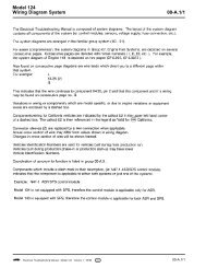
A. HAND-HELD TESTER (HHT) MODULE PLANNING OVERVIEW<br />
Periodic updates to HHT Modules and the introduction of new HHT<br />
Modules ensure that the dealer technician is provided with the very<br />
latest diagnostic information concurrent to production changes and the<br />
introduction of new modules. Therefore, it is very important to use<br />
the latest HHT Module available when performing <strong>diagnosis</strong>. The<br />
following table provides an overview of HHT Module planning.<br />
MODULE PLANNING OVERVIEW<br />
ÄÄÄÄÄÄÂÄÄÄÄÄÄÄÄÄÄÄÄÄÂÄÄÄÄÄÄÄÄÄÄÄÄÄÄÄÄÄÄÄÄÄÄÄÄÄÄÄÄÄÄÄÄÄÄÄÄÄÄÄÄÄÄÄÄÄÄÄÄÄ<br />
Issue ³ Model ³ Comments<br />
³ Application ³<br />
ÄÄÄÄÄÄÅÄÄÄÄÄÄÄÄÄÄÄÄÄÅÄÄÄÄÄÄÄÄÄÄÄÄÄÄÄÄÄÄÄÄÄÄÄÄÄÄÄÄÄÄÄÄÄÄÄÄÄÄÄÄÄÄÄÄÄÄÄÄÄ<br />
1/94 ³ 124, 129 ³ Obsolete (replaced by 12/94 issue, see below).<br />
ÄÄÄÄÄÄÅÄÄÄÄÄÄÄÄÄÄÄÄÄÅÄÄÄÄÄÄÄÄÄÄÄÄÄÄÄÄÄÄÄÄÄÄÄÄÄÄÄÄÄÄÄÄÄÄÄÄÄÄÄÄÄÄÄÄÄÄÄÄÄ<br />
3/94 ³ 140 ³ Obsolete (replaced by 12/94 issue, see below).
ÄÄÄÄÄÄÅÄÄÄÄÄÄÄÄÄÄÄÄÄÅÄÄÄÄÄÄÄÄÄÄÄÄÄÄÄÄÄÄÄÄÄÄÄÄÄÄÄÄÄÄÄÄÄÄÄÄÄÄÄÄÄÄÄÄÄÄÄÄÄ<br />
6/94 ³ 202 ³ Obsolete (replaced by 12/94 issue, see below).<br />
ÄÄÄÄÄÄÅÄÄÄÄÄÄÄÄÄÄÄÄÄÅÄÄÄÄÄÄÄÄÄÄÄÄÄÄÄÄÄÄÄÄÄÄÄÄÄÄÄÄÄÄÄÄÄÄÄÄÄÄÄÄÄÄÄÄÄÄÄÄÄ<br />
12/94 ³ 124, 129, ³ New issue<br />
³ 140, 202 ³ (replacement for 1/94, 3/94, 6/94 issues).<br />
ÄÄÄÄÄÄÁÄÄÄÄÄÄÄÄÄÄÄÄÄÁÄÄÄÄÄÄÄÄÄÄÄÄÄÄÄÄÄÄÄÄÄÄÄÄÄÄÄÄÄÄÄÄÄÄÄÄÄÄÄÄÄÄÄÄÄÄÄÄÄ<br />
IMPORTANT NOTE: Obsolete module 1/94, 3/94 and 6/94 are NOT to be<br />
returned at this time. Please store these modules<br />
with the new module in the HHT carrying case. Do not<br />
discard these obsolete modules as you will forfeit<br />
their core charge ($ 400.00 ea.)! Dealer will be<br />
informed as to handling procedures regarding these<br />
modules in the future.<br />
For further details regarding the HHT Module Program Update Service,<br />
please refer to S.I. MBNA 58/77A, 99/162A. January 1995.<br />
B. INTRODUCTION OF 4 MBYTE MODULE<br />
The release of the 12/94 HHT module marks the introduction of a 4<br />
MByte module which provides diagnostic coverage for all models<br />
including models 124, 129, 140 and 202. The integration of the three<br />
previously valid modules into one module will allow the user to<br />
quickly determine the status of modules on hand and will allow for<br />
easier updating, currently planned to take place approx. 4 times per<br />
year.<br />
The past, often confusing practice of including updated diagnostic<br />
information for a particular model on a module labeled for use only<br />
with a different model should no longer occur.<br />
The timeliness of future module updates is also scheduled for<br />
improvement with the decision to perform the update service locally at<br />
the Customer Assistance Center (CAC) in Montvale. New Jersey. Further<br />
details regarding revisions to the update service will be released at<br />
the modules next update.<br />
END OF ARTICLE<br />
HAND-HE
![[Buying Guide] - W124 Performance](https://img.yumpu.com/51307820/1/190x245/buying-guide-w124-performance.jpg?quality=85)