Lighthawk - Hubbell Building Automation
Lighthawk - Hubbell Building Automation
Lighthawk - Hubbell Building Automation

Create successful ePaper yourself
Turn your PDF publications into a flip-book with our unique Google optimized e-Paper software.
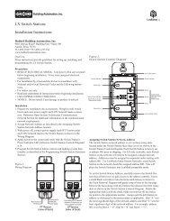
LightHawk Wall Switch Occupancy Sensors<br />
Installation and Operating Instructions<br />
<strong>Hubbell</strong> <strong>Building</strong> <strong>Automation</strong>, Inc.<br />
9601 Dessau Road, <strong>Building</strong> One, Suite 100<br />
Austin, Texas 78754<br />
512-450-1100 • 512-450-1215 Fax<br />
www.hubbell-automation.com<br />
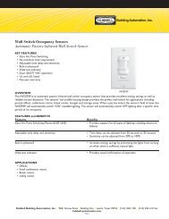
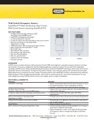
Description<br />
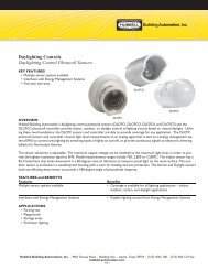
The LightHAWK is an intelligent self-adapting occupancy sensor that is<br />
designed to replace existing wall switches.<br />
Specifications<br />
• 1000 sq. ft coverage area (Models: LHIR and LHMT)<br />
• 400 sq. ft. coverage area (Models: LHUS)<br />
• Single or Dual circuit 120/277VAC, 50/60Hz operation<br />
• Single or Dual circuit 347VAC 60Hz operation (Canadian version)<br />
• Electrical Ratings: (Each Output Separately)<br />
120VAC – 800W Incandescent, 1000W Ballast, 1/6 HP<br />
277VAC – 1800W Ballast, 1/6 HP<br />
347VAC – 3470W Ballast (Canadian version)<br />
• Adjustable Time Delay: 4-30 minutes, self-adapts based<br />
on occupancy<br />
• Light Level Adjustment (Circuit B output on Dual Circuit versions):<br />
10-500+FC<br />
• UL, cUL listed<br />
Precautions<br />
CAUTION: RISK OF ELECTRICAL SHOCK. Turn power off at<br />
service panel before beginning installation. Never wire energized electrical<br />
components.<br />
Read and understand all instructions before beginning installation.<br />
NOTICE: For installation by a licensed electrician in accordance with<br />
National and/or local Electrical Codes and the following instructions.<br />
NOTICE: For indoor use only.<br />
CAUTION: USE COPPER CONDUCTOR ONLY.<br />
Confirm that device ratings are suitable for application prior to installation.<br />
NOTICE: Do not install if any damage to product is noticed.<br />
Installation<br />
1. Turn power off at the service panel.<br />
2. Remove the old switch(es) if applicable.<br />
3. Wire as shown in the Wiring Diagram section. A secure connection<br />
to ground is necessary for the sensor to function properly.<br />
4. Install sensor in wall box using mounting screws provided.<br />
5. Restore power to the sensor and allow it to warm up (up to 2 min.).<br />
6. Remove the sensor’s cover – see Adjustments section.<br />
7. If desired, calibrate the photocell sensor and adjust the sensor’s<br />
configuration switch settings as described below.<br />
8. Reinstall the sensor’s cover.<br />
9. Install a Decorator style wall plate (not included).<br />
Test Mode – to enter test mode:<br />
1. Make sure lights are on.<br />
2. Press and hold the ON/OFF button until the lights cycle off then back<br />
on. For dual circuit sensors, press and hold the ON/OFF button for<br />
Circuit A. For No-button sensors, press and hold the Test Button.<br />
See Sensor Operation Diagram.<br />
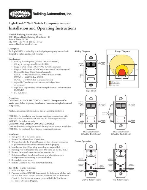
Wiring Diagram<br />
Sensor Operation<br />
Range Diagram
3. Sensor is now in test mode. Vacate room, lights should turn OFF after<br />
5 seconds. Wait 5 seconds after turn OFF before re-entering space,<br />
for US only sensors wait 15 seconds. Step back into room (sensing<br />
zone), lights will turn back on. Repeat as necessary to confirm sensor<br />
is operating and detecting in the lighting zone as desired. Sensor will<br />
flash red or green LED while occupied to indicate Passive Infrared<br />
or Ultrasonic occupancy detection respectively.<br />
4. To exit Test Mode, press any button. Note: Sensor will automatically<br />
exit Test Mode after 1 hour.<br />
Manual Override – Press button(s) to toggle lights ON or OFF. Lights<br />
will remain in the last state determined by the buttons while occupancy<br />
is detected. Sensor will return to automatic mode when the sensor’s<br />
unoccupied timer value is reached. Note: No-button sensors cannot be<br />
manually turned off.<br />
Air-Gap Override – If it is necessary to service the controlled circuits<br />
without de-energizing them at the breaker panel (this is not recommended<br />
as a standard procedure):<br />
1. Remove the sensor’s cover plate (see Adjustments section).<br />
2. With the circuit(s) on, turn the air-gap switch to OFF<br />
(toward the outside of the sensor).<br />
3. Push the button(s) to turn the circuit(s) OFF.<br />
4. Push the button(s) again to verify override.<br />
The air-gap switch will now interrupt sensor operation, preventing<br />
output(s) from turning on again, regardless of occupancy or pushbutton<br />
conditions. To return the sensor to normal operation, flip the air-gap<br />
switch to the ON position and push the button(s) to return the circuit(s) to<br />
Automatic mode. Re-install the sensor cover. Note: Sensor cover cannot be<br />
re-installed unless the air-gap switch is in the ON position.<br />
Adjustments<br />
Open the sensor cover by inserting a small blade screwdriver into the<br />
catch at the bottom of the sensor and gently snap the cover loose. Set the<br />
adjustment switches as desired (see Configuration Switch Settings below).<br />
To re-install cover, insert catches at top of cover into recesses in sensor<br />
housing and gently snap cover into catch at bottom of housing.<br />
Photocell<br />
The photocell is used to detect if other light sources such as sunlight, are<br />
enough to illuminate the space without turning on the lights. For Dual<br />
Circuit versions, only Circuit B is controlled by the photocell. The sensor is<br />
shipped from the factory with the photocell control disabled. If use of the<br />
photocell is desired, calibrate the photocell set points as follows:<br />
1. Remove the sensor’s cover plate.<br />
2. With the sunlight at the desired level where the controlled lights should<br />
be off, press the photocell button.<br />
3. Step back from the sensor to avoid changing ambient light levels in the<br />
room. Note: During calibration the sensor will turn the lights off<br />
and on.<br />
4. After the calibration process is complete (approx. 7 min.), reinstall<br />
sensor cover. (Calibration is over when LED’s blink in response to<br />
motion.)<br />
Switch 1 – Auto/Manual<br />
Controls selection between Auto ON/Auto OFF Mode and Manual ON/<br />
Auto OFF Mode. For Dual Circuit versions, this switch controls Auto/<br />
Manual Mode for Circuit A only. (Manual ON/Auto off mode requires A<br />
button push to turn lights ON.)<br />
Switch 2 – Auto/Manual B (Dual Circuit Versions Only)<br />
Controls selection between Auto ON/Auto OFF Mode and Manual ON/<br />
Auto OFF Mode for Circuit B.<br />
Switch 3 – Photocell Mode<br />
Controls selection between One Way Mode and Continuous Mode. In<br />
One Way Mode, the sensor turns lights on in response to occupancy<br />
when light levels are below the photocell set point then maintains them<br />
in the on condition regardless of light level. In Continuous Mode, the<br />
sensor functions the same as One Way Mode, except that during periods<br />
of occupancy it will turn the lights off if ambient light levels increase<br />
sufficiently to illuminate the space. Note: For Dual Circuit versions, the<br />
photocell controls the operation of Circuit B only.<br />
Switches 4 and 5 – Timer 1 and Timer 0<br />
Use to set the initial timer value that the sensor will maintain lights on<br />
without detecting occupancy. See Auto/Fixed Timer below for additional<br />
information.<br />
Switch 6 – Auto/Fixed Timer<br />
Controls selection between Adaptive Timer Mode and Fixed Timer Mode.<br />
In Automatic Adaptive Timer Mode, the sensor will use the timer interval<br />
setting from switches Timer 0 and Timer 1 above. It will then begin<br />
adjusting it’s timer settings as appropriate for the lighted space to optimize<br />
performance based on occupancy patterns. In Fixed Timer Mode, the<br />
sensor’s self-adapting timer functions are disabled and the sensor maintains<br />
the lights in the space according to the switch settings of Timer 0 and<br />
Timer 1.<br />
Switch 7 – Hallway<br />
Disables or enables the sensor’s hallway algorithm. When enabled, this<br />
feature reduces false tripping of the lights associated with hallway traffic<br />
outside the room where the sensor is controlling the lights. This feature<br />
should be enabled when the sensor’s range of detection extends into a<br />
hallway or adjoining areas with occupancy.<br />
Switch 8 – Adaptive Reset<br />
When toggled on then off, this switch resets the sensor’s adaptive timer<br />
and sensitivity settings. The adaptive timer is reset according to Timer 0<br />
and Timer 1 above. The adaptive sensitivity (both PIR and Ultrasonic as<br />
applicable) are reset to factory default. The Photocell Sensor is also reset<br />
to factory default (disabled) such that the sensor will turn on the light(s) in<br />
response to occupancy regardless of ambient light levels in the lighted space.<br />
Configuration Switch Settings<br />
Switch Settings (as seen on front of sensor)<br />
switch toggle direction<br />
Switch<br />
Function<br />
8 Sensitivity/Timer/Photocell Enable Adaptation Restore Factory Defaults<br />
7 Hallway Mode Disable Enable<br />
6 Timer Mode Automatic Fixed<br />
5 Timer Select 1