VigorAccess A48 User's Guide i - Draytek
VigorAccess A48 User's Guide i - Draytek
VigorAccess A48 User's Guide i - Draytek

Create successful ePaper yourself
Turn your PDF publications into a flip-book with our unique Google optimized e-Paper software.
i<br />
<strong>VigorAccess</strong> <strong>A48</strong> User’s <strong>Guide</strong>
<strong>VigorAccess</strong> <strong>A48</strong> User’s <strong>Guide</strong><br />
ii
<strong>VigorAccess</strong> <strong>A48</strong> Series<br />
ADSL2/2+ IP DSLAM<br />
User’s <strong>Guide</strong><br />
Version: 1.0<br />
Date: 25/06/2009<br />
This manual is available for Vigor Access with Annex A (Annex M and<br />
Annex L)/Annex B.<br />
iii<br />
<strong>VigorAccess</strong> <strong>A48</strong> User’s <strong>Guide</strong>
Copyright Information<br />
Copyright<br />
Declarations<br />
Trademarks<br />
Safety Instructions and Approval<br />
Safety<br />
Instructions<br />
Warranty<br />
Copyright 2009 All rights reserved. This publication contains information that is<br />
protected by copyright. No part may be reproduced, transmitted, transcribed,<br />
stored in a retrieval system, or translated into any language without written<br />
permission from the copyright holders.<br />
The following trademarks are used in this document:<br />
• Microsoft is a registered trademark of Microsoft Corp.<br />
• Windows, Windows 95, 98, Me, NT, 2000, XP, Vista and Explorer are<br />
trademarks of Microsoft Corp.<br />
• Apple and Mac OS are registered trademarks of Apple Inc.<br />
• Other products may be trademarks or registered trademarks of their<br />
respective manufacturers.<br />
• Make sure that the AC power source is in the range of AC 90-260V. The<br />
<strong>VigorAccess</strong> should be used in a sheltered area, within a temperature range<br />
from -10 to +65 °C and relative humidity in the range of 10% and 95%.<br />
• DC power source operating condition: -42 to –56VDC. Do not expose the<br />
<strong>VigorAccess</strong> to direct sunlight or other heat sources. The housing and<br />
electronic components may be damaged by direct sunlight or heat sources.<br />
• Read the manual before turning on the power switch of device.<br />
• Locate the emergency power-off switch near the device prior to power<br />
connection.<br />
• Fixing the device on chassis to maintain air circulation and stable<br />
condition is recommended.<br />
• Do not work alone if the operation environment is dangerous.<br />
• Check and avoid the potential hazard for moist environment, and<br />
grounding issue for power cable.<br />
• Please turn off the power switch when replacing fuse, installing or<br />
removing chassis.<br />
• Do not place the device in a damp or humid place, e.g. a bathroom- (such<br />
as this environment).<br />
• Avoid operating cable connection during lightning period.<br />
• When you want to dispose of the <strong>VigorAccess</strong>, please follow local<br />
regulations on conservation of the environment.<br />
• Users can replace fuses by removing the module and replace it when<br />
necessary. Other components should be repaired by authorized and<br />
qualified personnel. Do not try to open or repair the device by yourself.<br />
• The fuse for AC power inlet should be identical to the following standard:<br />
250VAC, 2A<br />
We warrant to the original end user (purchaser) that the router will be free from<br />
any defects in workmanship or materials for a period of two (2) years from the<br />
date of purchase from the dealer. Please keep your purchase receipt in a safe<br />
place as it serves as proof of date of purchase. During the warranty period, and<br />
upon proof of purchase, should the product have indications of failure due to<br />
faulty workmanship and/or materials, we will, at our discretion, repair or replace<br />
the defective products or components, without charge for either parts or labor, to<br />
whatever extent we deem necessary tore-store the product to proper operating<br />
condition. Any replacement will consist of a new or re-manufactured<br />
functionally equivalent product of equal value, and will be offered solely at our<br />
discretion. This warranty will not apply if the product is modified, misused,<br />
tampered with, damaged by an act of God, or subjected to abnormal working<br />
conditions. The warranty does not cover the bundled or licensed software of<br />
other vendors. Defects which do not significantly affect the usability of the<br />
product will not be covered by the warranty. We reserve the right to revise the<br />
manual and online documentation and to make changes from time to time in the<br />
contents hereof without obligation to notify any person of such revision or<br />
<strong>VigorAccess</strong> <strong>A48</strong> User’s <strong>Guide</strong><br />
iv
Be a Registered<br />
Owner<br />
Firmware & Tools<br />
Updates<br />
changes.<br />
Web registration is preferred. You can register your <strong>VigorAccess</strong> via<br />
http://www.draytek.com. Alternatively, fill in the registration card and mail it to<br />
the address found on the reverse side of the card.<br />
Due to the continuous evolution of DrayTek technology, all IP DSLAMs will be<br />
regularly upgraded. Please consult the DrayTek web site for more information on<br />
newest firmware, tools and documents.<br />
http://www.draytek.com<br />
European Community Declarations<br />
Manufacturer: DrayTek Corp.<br />
Address: No. 26, Fu Shing Road, HuKou Township, HsinChu Industrial Park, Hsin-Chu, Taiwan<br />
303<br />
Product: <strong>VigorAccess</strong> IP DSLAM <strong>A48</strong><br />
DrayTek Corp. declares that <strong>VigorAccess</strong> is in compliance with the following essential requirements and<br />
other relevant provisions of R&TTE Directive 1999/5/EEC.<br />
The product conforms to the requirements of Electro-Magnetic Compatibility (EMC) Directive<br />
2004/108/EC by complying with the requirements set forth in EN55022/Class A and EN55024/Class A.<br />
The product conforms to the requirements of Low Voltage (LVD) Directive 2006/95/EC by complying<br />
with the requirements set forth in EN60950-1.<br />
Regulatory Information<br />
Federal Communication Commission Interference Statement<br />
This equipment has been tested and found to comply with the limits for a Class A digital device, pursuant<br />
to Part 15 of the FCC Rules. These limits are designed to provide reasonable protection against harmful<br />
interference in a residential installation. This equipment generates, uses and can radiate radio frequency<br />
energy and, if not installed and used in accordance with the instructions, may cause harmful interference to<br />
radio communications. However, there is no guarantee that interference will not occur in a particular<br />
installation. If this equipment does cause harmful interference to radio or television reception, which can<br />
be determined by turning the equipment off and on, the user is encouraged to try to correct the interference<br />
by one of the following measures:<br />
• Reorient or relocate the receiving antenna.<br />
• Increase the separation between the equipment and receiver.<br />
• Connect the equipment into an outlet on a circuit different from that to which the receiver is<br />
connected.<br />
• Consult the dealer or an experienced radio/TV technician for help.<br />
This device complies with Part 15 of the FCC Rules. Operation is subject to the following two conditions:<br />
(1) This device may not cause harmful interference, and<br />
(2) This device may accept any interference received, including interference that may cause undesired<br />
operation.<br />
v<br />
<strong>VigorAccess</strong> <strong>A48</strong> User’s <strong>Guide</strong>
Taiwanese BSMI (Bureau of Standards, Metrology and Inspection) A Warning:<br />
Warning: This device might cause interference of radio frequency under the environment of dwelling. In<br />
such condition, the users might be asked to adopt some proper strategies.<br />
Please visit http://www.draytek.com/user/AboutRegulatory.php<br />
This product is designed for the DSL network throughout the EC region and Switzerland with restrictions<br />
in France. Please see the user manual for the applicable networks on your product.<br />
Customer Support<br />
Please prepare the following information before you contact your customer support.<br />
• Product model and serial number<br />
• Warranty information<br />
• Date that you received <strong>VigorAccess</strong><br />
• Product configuration<br />
• Software release version number<br />
• Brief description of your problem<br />
The information of customer supports and sales representatives is in www.DrayTek.com, respectively.<br />
<strong>VigorAccess</strong> <strong>A48</strong> User’s <strong>Guide</strong><br />
vi
Table of Contents<br />
1. Introduction........................................................................................................... 1<br />
1.1 Features of <strong>VigorAccess</strong> ............................................................................................................ 1<br />
1.2 Applications ................................................................................................................................ 6<br />
1.2.1 General Application Scenario ....................................................................................... 7<br />
1.2.2 Commercial Application Scenario ................................................................................. 8<br />
1.3 Panel Explanation ...................................................................................................................... 9<br />
2. Installation and Connection................................................................................11<br />
2.1 Rack-Mounted Installation........................................................................................................ 12<br />
2.2 Desktop Placement .................................................................................................................. 12<br />
2.3 Frame Ground Installation........................................................................................................ 13<br />
2.4 ADSL Port Connection ............................................................................................................. 14<br />
2.4.1 MDF (Main Distribution Frame)................................................................................... 14<br />
2.4.2 Scenario – Standalone................................................................................................ 15<br />
2.4.3 Scenario – Cascade Installation ................................................................................. 16<br />
2.4.4 Scenario – A24M and Six <strong>A48</strong> Devices ...................................................................... 18<br />
2.4.5 CPP (Centric Patch Panel) ......................................................................................... 20<br />
2.5 Power Connection.................................................................................................................... 22<br />
2.6 Optical Fiber Connection (SFP Optional)................................................................................. 24<br />
2.7 Console Port Connection ......................................................................................................... 26<br />
3. Web Configuration.............................................................................................. 27<br />
3.1 System Configuration............................................................................................................... 27<br />
3.1.1 Status .......................................................................................................................... 28<br />
3.1.2 SNMP Config .............................................................................................................. 29<br />
3.1.3 IP Config ..................................................................................................................... 30<br />
3.1.4 Default Route .............................................................................................................. 30<br />
3.1.5 Commit........................................................................................................................ 31<br />
3.1.6 Reboot......................................................................................................................... 31<br />
3.1.7 Firmware Upgrade ...................................................................................................... 31<br />
3.1.8 Configuration Backup/Restore .................................................................................... 34<br />
3.2 DSL Configuration .................................................................................................................... 36<br />
3.2.1 Line Profile .................................................................................................................. 36<br />
3.2.2 DSL Show ................................................................................................................... 39<br />
3.2.3 Performance................................................................................................................ 41<br />
3.3 PVC Configuration.................................................................................................................... 41<br />
3.3.1 PVC............................................................................................................................. 42<br />
3.3.2 Mac Profile .................................................................................................................. 44<br />
3.4 Bridge Configuration................................................................................................................. 44<br />
3.4.1 VLAN........................................................................................................................... 45<br />
3.4.2 Bridge.......................................................................................................................... 47<br />
3.4.3 Qos Profile .................................................................................................................. 49<br />
Appendix A: Connectors........................................................................................ 51<br />
A.1 RJ21 DSL Connector ............................................................................................................... 51<br />
vii<br />
<strong>VigorAccess</strong> <strong>A48</strong> User’s <strong>Guide</strong>
A.2 Alarm Relay RJ45 Connector ..................................................................................................52<br />
A.3 Alarm Port RJ45 Connector ..................................................................................................... 52<br />
A.4 RS232 Connector .................................................................................................................... 53<br />
A.5 Standard 10/100 Base-T Ethernet Interface Connector .......................................................... 54<br />
A.6 Standard 10/100/1000 Base-T Ethernet Interface Connector ................................................. 55<br />
A.7 Contacting Your Dealer............................................................................................................ 55<br />
<strong>VigorAccess</strong> <strong>A48</strong> User’s <strong>Guide</strong><br />
viii
1. Introduction<br />
With the explosive growth of Internet, people are becoming more and more relying on<br />
Internet in daily life. The rapidly increase in bandwidth demanded by digital society has<br />
put pressure on the network therefore, bandwidth and performance management are<br />
becoming critical issue for ISP.<br />
<strong>VigorAccess</strong>, which is equipped with 48 ADSL2/+ ports, is designed for ISP (Internet<br />
Service Provider) to implement bandwidth management for multiple subscribers. As<br />
<strong>VigorAccess</strong> supports high upstream and downstream bit-rates performance, therefore,<br />
<strong>VigorAccess</strong> is being deployed primarily for residential customer for IPTV application or<br />
high speed Internet service or business customers to replace expensive T1/E1 leased line.<br />
<strong>VigorAccess</strong> is not only equipped with a console port being used for local management,<br />
but also provided excellent capabilities of SNMP, Telnet for remote management. In<br />
particular, <strong>VigorAccess</strong> can be easily configured by EMS. The EMS system covers<br />
topology, configuration, deployment, security, alarm management and backed storage.<br />
Moreover, with the solution of port-based and tag-based VLAN, <strong>VigorAccess</strong> can isolate<br />
traffic between different users and provide improved security.<br />
1.1 Features of <strong>VigorAccess</strong><br />
The <strong>VigorAccess</strong> (Integrated Ethernet Switch) is an IP-based DSLAM (Internet Digital<br />
Subscriber Line Access Multiplexer) that connects to 48 ADSL subscribers to the Internet.<br />
When deployed together with DSL modems and WAN routers, the combination forms are<br />
integrated solution for providing broadband services to multiple tenants such as<br />
apartments, hotels, offices and campus buildings. <strong>VigorAccess</strong> supports a lot of features<br />
as listed below.<br />
• ADSL Access Module<br />
The name marked “Line” on the front panel is a RJ-21 connector integrated 24<br />
ADSL ports internally. It aggregates traffic from 48 lines to Ethernet port(s) and has<br />
integrated splitters to allow voice and ADSL to be carried over the same phone line<br />
wiring.<br />
• 10/100/1000 Mbps Auto-negotiating Ethernet Port<br />
<strong>VigorAccess</strong> supports FE/GE auto-negotiate Ethernet ports connecting to an<br />
Ethernet network. It can be aggregated together as a logical port as the backbone,<br />
and provide ADSL service to lots of subscribers.<br />
• ADSL Compliance<br />
‣ Multi-Mode ADSL standard<br />
‣ G.dmt (ITU-T G.992.1)<br />
‣ G.dmt.bis (ADSL2, G.992.3)<br />
‣ G.dmt.bisplus (ADSL2plus, G.992.5)<br />
‣ G.lite (ITU-T G.992.2)<br />
‣ G.hs (ITU-T G.994.1)<br />
‣ ANSI T1.413 issue 2<br />
1<br />
<strong>VigorAccess</strong> <strong>A48</strong> User’s <strong>Guide</strong>
• Ethernet Bridging<br />
‣ IEEE 802.1d STD transparent bridging<br />
‣ Up to 4000 MAC entries address table<br />
‣ Port-based VLAN<br />
• IEEE 802.1Q Tagged VLAN<br />
<strong>VigorAccess</strong> uses the IEEE 802.1Q Tagged VLAN; users can allow this device to<br />
deliver tagged/untagged frames in these ports. <strong>VigorAccess</strong> supports up to 512<br />
VLAN groups and can be applied up to 4094 VLAN identifications.<br />
• IEEE 802.1p Priority<br />
<strong>VigorAccess</strong> supports IEEE 802.1p to assign priority levels to all individual ports.<br />
Users can set different quality of service for individual application.<br />
For example, voice and video services can set high priority and Internet data service<br />
will be lower priority.<br />
‣ Support 4 queues for per ATM port.<br />
‣ Support 8 queues for per physical Ethernet port.<br />
• MAC Address (Media Access Control) Filter<br />
‣ <strong>VigorAccess</strong> can let users use the MAC filter for incoming frames based on<br />
MAC (Media Access Control) addresses that specified by users. Users can<br />
enable/disable this function on specific port.<br />
Access Control List per port is up to 8 entries. If port receives a packet which<br />
source MAC address is met with one of the 8 entries, this packet can be<br />
forwarded to destination port.<br />
‣ Access Control List per device is up to 1024 entries. If port receives a packet<br />
which source MAC address is met with one of these entries, this packet would<br />
not be forwarded to destination port.<br />
The high priority of ACL rules is the allowing rule checking for per port.<br />
• MAC Address (Media Access Control) Count Filter<br />
<strong>VigorAccess</strong> supports users to limit the number of MAC addresses that may be<br />
dynamically learned or statically configured on a port. Users can enable/disable this<br />
function on individual ports.<br />
The global static learning table has up to 512 entries. Each entry can be set to a<br />
specific port. In dynamic learning mode, there are 16 MAC address entries in DSL<br />
port and 256 entries in Ethernet uplink port.<br />
• Multi-Protocol Encapsulation<br />
<strong>VigorAccess</strong> supports multi-protocol encapsulation over ATM adaptation Layer 5<br />
based on RFC2684.<br />
• Management<br />
<strong>VigorAccess</strong> supports some management method as listed below.<br />
‣ Remote configuration backup/restore via EMS client/server.<br />
‣ Remote firmware upgrade<br />
‣ SNMP management<br />
‣ Command Line Interface, it can be accessed by local Console or Telnet<br />
interface.<br />
<strong>VigorAccess</strong> <strong>A48</strong> User’s <strong>Guide</strong> 2
• Multiple PVC on single port<br />
<strong>VigorAccess</strong> allows you to use different virtual connection also called PVC<br />
(Permanent Virtual Circuits) for different services or subscribers. Users can define<br />
up to 8 connections on each DSL port for different services or levels of service, and<br />
users can assign different priority for each connection.<br />
• IGMP Snooping<br />
IGMP (Internet Group Management Protocol) snooping reduces multicast traffic for<br />
maximum performance. The feature is very popular for video multicast application<br />
for example IPTV service.<br />
• Load-sharing Redundancy<br />
These two Ethernet uplinks of <strong>VigorAccess</strong> can be used as a single load-shared<br />
uplink for data and management path, with a provision to fall back to single one, in<br />
the event one of the links failed.<br />
• Active Standby Redundancy<br />
These two Ethernet uplinks of <strong>VigorAccess</strong> can be used in an active stand by mode<br />
for data and management path, with a provision to fall back to standby link, in the<br />
event of the active links failure.<br />
• Configuration<br />
Modification of Ethernet IP address, mask, speed, and duplex mode is supported.<br />
Support for safe mode boot where the TE Image can be downloaded for field<br />
upgrade.<br />
Quality of Service (QoS)<br />
Quality of Service (QoS) refers to the capability of a network to provide better service to<br />
select network traffic over various technologies. The primary goal of QoS is to provide<br />
priority including dedicated bandwidth, controlled jitter and latency (required by some<br />
real-time and interactive traffic), and improved loss characteristics. Also it is important to<br />
make sure that providing priority for one or more flows does not make other flows fail.<br />
QoS technologies provide the elemental building blocks that will be used for future<br />
business applications in campus, WAN and service provider networks.<br />
• Prioritized Bridging<br />
<strong>VigorAccess</strong> supports for multiple queues per port. There are different queues both<br />
on ATM and Ethernet uplink.<br />
‣ Four queues supported per ATM port.<br />
‣ Eight queues supported per physical Ethernet port.<br />
• Scheduling Mechanism<br />
<strong>VigorAccess</strong> supports multiple scheduling mechanisms.<br />
‣ Strict Priority Scheduling<br />
‣ Probabilistic Priority Scheduling<br />
• Rate Limiting<br />
<strong>VigorAccess</strong> supports rate-limiting function in input/output both direction.<br />
‣ Input Rate Limiting (IRL) on a per-AAL5 interface.<br />
‣ Output Rate Limiting (ORL) on a per ATM-port basis<br />
‣ Output Rate Limiting (ORL) on a per-physical Ethernet Interface basis.<br />
One feature supports for buffer admission control triggered using IRL.<br />
Moreover, it also supports for dynamic modification of ORL on ATM and<br />
Ethernet interfaces.<br />
3<br />
<strong>VigorAccess</strong> <strong>A48</strong> User’s <strong>Guide</strong>
• Mapping Table<br />
<strong>VigorAccess</strong> supports a packet priority to traffic class mapping table supported on a<br />
per egress bridge port.<br />
• Multiple Mechanisms<br />
<strong>VigorAccess</strong> supports two multiple mechanisms as below.<br />
Multiple mechanisms of prioritizing incoming traffic are based on a per-bridge port.<br />
‣ Using Source Port configuration (for untagged packets)<br />
‣ Using Packet Classifier actions<br />
‣ Using priority regeneration table (mapping ingress priority to egress priority)<br />
‣ Combination of the above<br />
Multiple mechanisms of 802.1p re-tagging of outgoing traffic is based on a per<br />
ingress bridge port.<br />
‣ Using Source Port configuration (for untagged packets)<br />
‣ Using Classifier actions<br />
‣ Using priority regeneration table (mapping ingress priority to egress priority)<br />
‣ Combinations of the above<br />
• Abilities<br />
<strong>VigorAccess</strong> can be able to create multiple scheduling profiles, either Strict Priority<br />
or Probabilistic Priority. It also can be able to share the same profile across multiple<br />
(similar) ports.<br />
Security<br />
<strong>VigorAccess</strong> supports some different methods to implement this feature in following<br />
sections.<br />
• Rate Limitation<br />
<strong>VigorAccess</strong> supports a function for throttling flooded packets. Users can configure<br />
some limited rates by per-port.<br />
• Static Mac Address<br />
<strong>VigorAccess</strong> supports this feature to be configured with certain ports to learn MAC<br />
addresses on a semi-permanent basis. These learned entries would be treated similar<br />
to the static entries, but will not be subject to aging or overwriting. These only may<br />
be deleted explicitly by management or by making the ports, as non-static after<br />
aging will happen normally.<br />
• FDB Conflicting Traps<br />
<strong>VigorAccess</strong> will transmit a trap packet to central manager when any MAC address<br />
moves from one port to another port.<br />
• MAC Address Tracking<br />
<strong>VigorAccess</strong> can be configured to track a global list of MAC addresses. When these<br />
MAC addresses move from one port to another port, a trap is generated. Whether<br />
packets from a particular bridge port should be subjected to this tracking is<br />
configurable. This may be used to prevent denial of service from certain MAC<br />
addresses.<br />
• Access Control List by MAC address<br />
It can be configured by per-port. It also supports a MAC address deny list, the<br />
application of the MAC address deny list can be enabled/disabled on a per bridge<br />
port basis.<br />
<strong>VigorAccess</strong> <strong>A48</strong> User’s <strong>Guide</strong> 4
• Access Control List by IP Address<br />
This feature still can be configured by per-port, and enabled/disabled on a per<br />
bridge port basis.<br />
Packet Filtering<br />
This function is provided for users to setup some rules to filter the specific packets while<br />
receiving packets from logical ports.<br />
<strong>VigorAccess</strong> supports for rule-based packet filtering, it can be used to implement filtering<br />
required of NetBeui, NetBIOS, DHCP, 802.1x and other protocols.<br />
• Filtering Modes<br />
‣ <strong>VigorAccess</strong> supports for independent rule ordering and rule ID. It means that<br />
rule ID no longer determines the order in which the rule is applied. The rule can<br />
be modified easily; users can replace a rule sequence of a stage on an interface<br />
by another sequence in one step.<br />
‣ Moreover, <strong>VigorAccess</strong> also supports for capturing unicast and multicast<br />
packets that fail lookup in the forwarding database is provided. Users may write<br />
their own applications to terminate and act on this information. On the other<br />
side, it also supports for capturing packets coming to Control Plane that do not<br />
match any registered filter.<br />
• Multiple Filter Stages<br />
<strong>VigorAccess</strong> supports a concept of multiple filter stages are provided for ingress and<br />
egress filter rules. Moreover, <strong>VigorAccess</strong> supports an Egress filtering for unicast,<br />
broadcast and multicast traffic. It also supports multiple actions configurations by<br />
per filter rule.<br />
ATM Features<br />
<strong>VigorAccess</strong> supports some functions about ATM issue.<br />
• Remote CPE Management<br />
<strong>VigorAccess</strong> supports RAW AAL5 interface for remote CPE management.<br />
• Diagnostic Testing<br />
<strong>VigorAccess</strong> supports OAM-I.610 end-to-end and segment loop back and DELT.<br />
• Dynamic Modification<br />
<strong>VigorAccess</strong> supports a lot of dynamic modifications and is shown as below.<br />
‣ VPI/VCI value (VC should be disabled)<br />
‣ Transmit and receive PDU sizes<br />
‣ Management mode modification per port<br />
‣ Max VPI/VCI bits (interface must be disabled)<br />
‣ Maximum number of VCCs supported<br />
‣ OAM source ID<br />
5<br />
<strong>VigorAccess</strong> <strong>A48</strong> User’s <strong>Guide</strong>
1.2 Applications<br />
The compact design of <strong>VigorAccess</strong> is composed of DSL, optical interfaces, and 2<br />
subtend interfaces. <strong>VigorAccess</strong> provides lots of applications such as:<br />
High speed Internet Service - <strong>VigorAccess</strong> aggregates DSL subscribers and terminates<br />
the encapsulated type ATM cell. Users can easily access Internet through the IP backbone<br />
network.<br />
Gaming application Service - By combining gaming server, <strong>VigorAccess</strong> can provide<br />
gaming service.<br />
Stream TV Service - <strong>VigorAccess</strong> uses ADSL 2/+ high speed DSL technology, and<br />
supports stream TV Service.<br />
Video on Demand Service - Service provider can offer multimedia services by setting up<br />
video or content server on the local side. By combining rich content video server,<br />
<strong>VigorAccess</strong> also provides the video on demanded service. Users can easily access<br />
multimedia content based on <strong>VigorAccess</strong> architecture.<br />
Combined with VoIP Service - <strong>VigorAccess</strong> can combine IAD, DSL/VoIP gateway<br />
with highest priority to provide toll quality voice communication in terms of voice quality<br />
and reliability for the users.<br />
Mail or Portal Service - <strong>VigorAccess</strong> provides the feasibility to connect mail or proxy<br />
server.<br />
The following section provides general and commercial applications scenarios for your<br />
reference.<br />
<strong>VigorAccess</strong> <strong>A48</strong> User’s <strong>Guide</strong> 6
1.2.1 General Application Scenario<br />
Take the following figure as an example. For users living in the same building,<br />
<strong>VigorAccess</strong> can set up additional Video Server, Mail Server, Proxy Server and Game<br />
Server in the network different from the ones set up by ISP, and allows users to share the<br />
multiple services. In addition, the users can access into Intranet through WAN ports, to<br />
communicate with others with PSTN feature by using routers (CPE, Customer Premise<br />
Equipment) or IAD (Integrated Access Device). In general, <strong>VigorAccess</strong> can handle and<br />
control all of the services for saving user’s money with quick speed through Fiber<br />
connection, and it can simplify the construction procedure of network setup.<br />
7<br />
<strong>VigorAccess</strong> <strong>A48</strong> User’s <strong>Guide</strong>
1.2.2 Commercial Application Scenario<br />
<strong>VigorAccess</strong> is able to support enterprise customer with high-speed service request.<br />
Customers can subscribe multiple ADSL 2/+ lines by integrating security router with load<br />
balance feature. By combining VoIP devices, system integrator provides multiple services<br />
with VoIP, Video on Demand, and ADSL2/+ bundle solution, etc.<br />
In addition, the firewall and VPN security of VoIP security router is also provided by the<br />
architecture to meet business requirements. This application is suitable on Hotel and<br />
MTU (Multi-Tenant Unit) applications. The entire system is managed by EMS system.<br />
The following graphic shows the possible application for <strong>VigorAccess</strong> in business.<br />
<strong>VigorAccess</strong> <strong>A48</strong> User’s <strong>Guide</strong> 8
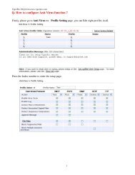
1.3 Panel Explanation<br />
The connectors on the front panel for the <strong>VigorAccess</strong> <strong>A48</strong> is shown below:<br />
Interface<br />
FAN MODULE<br />
DC1 ~ DC2<br />
FUSE-1 ~<br />
FUSE-2<br />
ALARM PORT<br />
CONSOLE<br />
G1 – G2<br />
G3 – G4<br />
FR (Factory<br />
Reset)<br />
PSTN<br />
LINE<br />
Description<br />
Support hot-swappable<br />
DC power connector (dual feed)<br />
Fuse-1 maps to DC1 and Fuse-2 maps to DC2.<br />
An alarm relay with RJ45 interface can connect to buzzer when the<br />
FAN is out of order.<br />
A RS232 serial interface is used to connect a local management<br />
computer.<br />
The subtend interface with RJ45 interface is Gigabit Ethernet<br />
connection.<br />
Slots used for SFP module.<br />
A reset button is used to reset system, and then IPDSLAM will<br />
operate by default configuration.<br />
Connected to PSTN normally.<br />
Connected to twist pair of subscriber line which connects ADSL<br />
devices or telephones for users.<br />
Warning:<br />
• The laser energy of the fiber optic communication channels in the single-mode<br />
will be harmful when operate, especially to the eyes. During normal operation<br />
with cable connection, this energy is confined to the cable with no danger<br />
present.<br />
• Never stare into an optical cable or connector when the connector is not in<br />
use.<br />
In addition, below shows the cables used in different connectors:<br />
Name Type, Color Connected to<br />
Power Cord<br />
RJ45 Cable<br />
Cord, Black<br />
Wire,<br />
RJ45 connect to<br />
Buzzer<br />
DC-1 or DC-2<br />
ALARM PORT connection.<br />
Serial Cable (Console) RS232, Grey PC RS232 port for CLI.<br />
G3-G4 Cable<br />
LC/RJ45,<br />
Yellow/Orange<br />
Gigabits Fiber Optical Interface<br />
Interconnection.<br />
9<br />
<strong>VigorAccess</strong> <strong>A48</strong> User’s <strong>Guide</strong>
RJ45 Cable for G1 –G2<br />
RJ-21 Cable for<br />
PHONE<br />
RJ-45 (8P8C),<br />
Blue<br />
RJ-21, Grey<br />
Connect to slave unit (UP1or UP2).<br />
MDF or Panel to PSTN.<br />
RJ-21 Cable for LINE RJ-21, Grey To subscriber copper line.<br />
LED Indication<br />
LED Status Explanation<br />
LNK Green Subtend interface by GE Interface.<br />
G1 – G2<br />
When the Ethernet link is established, it will blink<br />
during data transmitting/receiving.<br />
OFF It means no Ethernet link established.<br />
1000 Green The speed for Ethernet is 1000Mbps when LNK<br />
LED is on.<br />
OFF The speed for Ethernet is 10/100Mbps when LNK<br />
LED is on.<br />
G3-G4 LNK Green When the optical connection is established, it will<br />
blink during data transmitting/receiving.<br />
OFF It means no optical connection established.<br />
CR<br />
Green Critical alarm is present.<br />
OFF No critical alarm is present to system.<br />
MJ<br />
Green Major alarm is present.<br />
OFF No major alarm is present to system.<br />
MN<br />
Green Minor alarm is present.<br />
OFF No minor alarm is present to system.<br />
ACT<br />
Green It blinks when this device is active.<br />
OFF It is off when system is hanged.<br />
PWR<br />
Green The power LED is on when the power is applied.<br />
OFF The Power is not applied.<br />
DSL 1 - 48 Green The DSL 1-48 port link status is up.<br />
Blinking The DSL link is training.<br />
OFF The DSL x port link status is down.<br />
<strong>VigorAccess</strong> <strong>A48</strong> User’s <strong>Guide</strong> 10
2. Installation and Connection<br />
This section will guide you to install the <strong>VigorAccess</strong> through hardware connection<br />
To fully setup the <strong>VigorAccess</strong> connection, you have to finish the following items:<br />
• Rack-mounted installation<br />
• Line interface connection (ADSL port connection)<br />
• Phone interface connection<br />
Below shows an example of <strong>VigorAccess</strong> network connection for your reference.<br />
11<br />
<strong>VigorAccess</strong> <strong>A48</strong> User’s <strong>Guide</strong>
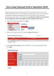
2.1 Rack-Mounted Installation<br />
<strong>VigorAccess</strong> can be installed on 19-, 23-inches racks by using standard brackets in<br />
19-inch rack or optional larger brackets on 23-inch rack with other equipments. The<br />
bracket for 19-, 23-inch racks are shown below.<br />
Attach the brackets to the chassis in 19-, 23-inch rack. The second bracket attaches the<br />
other side of the chassis as above procedure.<br />
After bracket installation, <strong>VigorAccess</strong> chassis could be installed in the rack by using two<br />
screws for each side of rack.<br />
2.2 Desktop Placement<br />
The <strong>VigorAccess</strong> can be placed on the rack or on a flat surface. There are four rubber feet<br />
attached on the bottom of the <strong>VigorAccess</strong> to stabilize the device for placing on a flat<br />
surface. These rubber feet aims to improve the air circulation, and at the same time it can<br />
decrease unnecessarily rubbing on the desk. Therefore, you can simply put the master or<br />
slave device on your desk or any plane surface without worrying damage.<br />
<strong>VigorAccess</strong> <strong>A48</strong> User’s <strong>Guide</strong> 12
2.3 Frame Ground Installation<br />
The frame ground is on the front of the <strong>VigorAccess</strong> which is powered by DC connector.<br />
Connect the frame ground to a building’s earthing terminal by using frame ground wire.<br />
Importance: Please connect the frame ground first before you connect any other<br />
cables for this device.<br />
13<br />
<strong>VigorAccess</strong> <strong>A48</strong> User’s <strong>Guide</strong>
2.4 ADSL Port Connection<br />
2.4.1 MDF (Main Distribution Frame)<br />
The PSTN splitter should be connected to MDF on building. An MDF is usually placed in<br />
the building’s telephony room or wiring closet. MDF can terminate the outside telephone<br />
line into the building. In general, the LINE and PHONE interface on the <strong>A48</strong> device will<br />
connect to MDFs respectively and then to outside connection.<br />
The traditional connection via MDFs for the phone set used in family is shown as the<br />
following picture. The telephone set must connect to one port (in this case, Port 1) of<br />
MDF-1, meanwhile that port must connect to corresponding place of MDF-2. Next, the<br />
other end of Port 1 (in MDF-2) will connect to PSTN.<br />
An example for MDF connection through <strong>VigorAccess</strong> is shown as the following picture.<br />
For different applications, you have to can change the connection according to the real<br />
circumstance that you encounter.<br />
<strong>VigorAccess</strong> <strong>A48</strong> User’s <strong>Guide</strong> 14
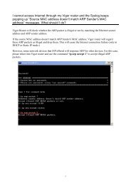
2.4.2 Scenario – Standalone<br />
<strong>A48</strong> is used standalone for it cannot manage any slave device. In such condition, it can<br />
connect and control 24 ADSL CPE routers with DB-21 cable through MDF connection.<br />
In the above picture, the user of PC-3 wants to use phone and access the Internet at the<br />
same time; yet PC-1 and PC-2 just want to access the Internet through the <strong>A48</strong> device. As<br />
for the connection, please follow the steps below:<br />
1. Connect PC-3 to number 9 of MDF-1, PC-2 to number 5 of MDF-1 and PC-1 to<br />
number 1 of MDF-1 with Ethernet cable.<br />
2. Connect the MDF-1 to Line port of the <strong>A48</strong> device.<br />
3. Connect the Phone port of the <strong>A48</strong> device to the matching connector (in this case, it<br />
is number 9, be careful and not to misconnect) to MDF-2 which will be connected to<br />
PSTN. This step is just useful for PC-3 for the user wants to call out through the <strong>A48</strong><br />
device.<br />
4. Connect the device and ISP with Fiber cable through G3-G4 port.<br />
5. With such connection, all the users of the PCs can access the Internet through<br />
G3-G4 connector of the device. Yet only PC-3 can call out with a telephone set<br />
directly.<br />
The device can connect 24 ADSL CPE routers which supported by the DB-21 cables. If<br />
you want to expand the usage for more users, we recommend you to purchase <strong>A48</strong><br />
device.<br />
15<br />
<strong>VigorAccess</strong> <strong>A48</strong> User’s <strong>Guide</strong>
2.4.3 Scenario – Cascade Installation<br />
For Master device and Slave device, at least there are 48 ADSL CPE routers can be<br />
connected to outside Internet via the Master device.<br />
The following picture shows the sample connection for <strong>A48</strong> devices. Here we take PC-1,<br />
PC-2 and PC-3 as the examples that connecting to the Slave device directly and wanting<br />
to access the Internet through the Master device.<br />
In the above picture, the user of PC-3 wants to use phone and access the Internet at the<br />
same time; yet PC-1 and PC-2 just want to access the Internet through the Slave and<br />
Master devices. As for the connection, please follow the steps below:<br />
1. Connect PC-3 to number 9 of MDF-1, PC-2 to number 5 of MDF-1 and PC-1 to<br />
number 1 of MDF-1.<br />
2. Connect the MDF-1 to Line port of the Slave device.<br />
3. Connect the Phone port of the Slave device to the matching connector (in this case,<br />
it is number 9, be careful and not to misconnect) to MDF-2 which will be connected<br />
to PSTN. This step is just useful for PC-3 for the user wants to call out through the<br />
connected Slave device.<br />
4. Slave devices can be connected to G1 or G2 port of the Master device with Ethernet<br />
cable.<br />
5. Connect the Master device and ISP with Fiber cable through G3 or G4 port.<br />
<strong>VigorAccess</strong> <strong>A48</strong> User’s <strong>Guide</strong> 16
6. With such connection, all the users of the PCs (connecting to Slave device) can<br />
access the Internet through fiber connector of the Master device. Yet only PC-3 can<br />
call out with a telephone set directly.<br />
Such connection allows 48 ADSL CPE routers to connect to outside Internet via the <strong>A48</strong><br />
device. If you want to connect more of the routers, please refer to next scenario for one<br />
A24 and six <strong>A48</strong> devices connection.<br />
17<br />
<strong>VigorAccess</strong> <strong>A48</strong> User’s <strong>Guide</strong>
2.4.4 Scenario – A24M and Six <strong>A48</strong> Devices<br />
The following picture shows the sample connection between six <strong>A48</strong> devices and one<br />
A24M device. Here we take PC-1, PC-2 and PC-3 as the examples that connecting to one<br />
<strong>A48</strong> directly and wanting to access the Internet through A24M device.<br />
In the above picture, the user of PC-3 wants to use phone and access the Internet at the<br />
same time; yet PC-1 and PC-2 just want to access the Internet through the connected<br />
Slave and Master devices. As for the connection, please follow the steps below:<br />
1. Connect PC-3 to number 9 of MDF-1, PC-2 to number 5 of MDF-1 and PC-1 to<br />
number 1 of MDF-1 with Ethernet cable).<br />
2. Connect the MDF-1 to Line port of the Slave Device -1.<br />
3. Connect the Phone port of the Slave Device-1 to the matching connector (in this case,<br />
it is number 9, be careful and not to misconnect) to MDF-2 which will be connected<br />
to PSTN. This step is just useful for PC-3 for the user wants to call out through the<br />
Slave Device-1.<br />
4. Connect G1 or G2 port of the Slave Device-1 and G6 port of the Master device with<br />
Ethernet cable. As to the connection among the Master device and Slave Device-2 to<br />
Slave Device-6, please refer to arrow indication shown on the picture.<br />
5. Connect the Master device and ISP with Fiber cable through G3 or G4 port.<br />
6. With such connection, all the users of the PCs (connecting to the Slave devices) can<br />
access the Internet through G3 or G4 connector of the Master device. Yet only PC-3<br />
can call out with a telephone set directly.<br />
Such connection allows 168 ADSL CPE routers (24 from the Master device and 144 from<br />
the Slave Device-1 to Slave Device-6) to connect to outside Internet via the Master device<br />
at one time.<br />
<strong>VigorAccess</strong> <strong>A48</strong> User’s <strong>Guide</strong> 18
To make the required configuration for master and slave devices, use CLI command.<br />
Admin> dsl -m<br />
Press 'exit' to return<br />
Entering character mode<br />
Escape character is '^]'.<br />
[dsl-master]#<br />
or<br />
Admin> dsl -s <br />
Press 'exit' to return<br />
Entering character mode<br />
Escape character is '^]'.<br />
[dsl-slave-n]#<br />
19<br />
<strong>VigorAccess</strong> <strong>A48</strong> User’s <strong>Guide</strong>
2.4.5 CPP (Centric Patch Panel)<br />
The <strong>VigorAccess</strong> can provide ADSL and voice services over the same telephone wiring.<br />
It also has built in splitters internally that can save space and simplify installation.<br />
If the application is using on building environment, the CPP (Centric Patch Panel) is<br />
preferred. The purpose of CPP module is to transfer RJ-21 jack in <strong>VigorAccess</strong> to<br />
RJ-11 connector. It is usually installed between end-users’ equipment and telephone<br />
company in a basement or telephone room. The CPP is the point of termination for the<br />
outside telephone company lines coming into a building and the telephone lines in the<br />
building.<br />
The existing telephone wiring usually depends on user’s region. Here are descriptions of<br />
two typical installation scenarios. Use telephone wires with RJ-11 jacks on one end for<br />
connecting to the CPP board.<br />
Scenario A<br />
Users can connect a cable from RJ-21 (LINE) attached in <strong>VigorAccess</strong> to the CPP board.<br />
Then users can connect a RJ-11 jack port attached in a CPP to ADSL modem directly.<br />
The following example shows the connection for data transmission only through CPP.<br />
<strong>VigorAccess</strong> <strong>A48</strong> User’s <strong>Guide</strong> 20
Scenario B<br />
Phone service is available in <strong>VigorAccess</strong>. You can connect a RJ-11 jack port attached in<br />
a CPP to a telephone directly or applied in the same way shared in ADSL modem. The<br />
following example shows the connection for Data/Voice transmission through CPP.<br />
21<br />
<strong>VigorAccess</strong> <strong>A48</strong> User’s <strong>Guide</strong>
2.5 Power Connection<br />
Before you purchasing the device, please check your environment to determine which<br />
power type that matches with your requirement.<br />
Get acquainted with the following parts first:<br />
DC Power Cord Y type terminator DC Power Terminator Head<br />
Follow the steps below to complete the power cord combination.<br />
1. Insert the DC Power Cord into the socket of DC Power Terminator Head.<br />
2. Use the screwdriver to fasten the power cord inside the head.<br />
3. The assembled power cord with head should be the same as the following:<br />
<strong>VigorAccess</strong> <strong>A48</strong> User’s <strong>Guide</strong> 22
4. Plug the power cord head into the DC-1/DC-2 connector on <strong>A48</strong>.<br />
Warning: The above figure shows the DC power supply terminal block. It is the lugs<br />
at the wiring end from the power source. The wiring procedure is for<br />
ground-to-ground, positive-to-positive, and negative-to-negative in order. The<br />
ground wire should always be connected first and disconnected last.<br />
23<br />
<strong>VigorAccess</strong> <strong>A48</strong> User’s <strong>Guide</strong>
2.6 Optical Fiber Connection (SFP Optional)<br />
Before you start to do the optical fiber connection, please read the following warnings<br />
first.<br />
Warnings:<br />
• The laser energy of the fiber optic communication channels in the single-mode<br />
will be harmful when operate, especially to the eyes. During normal operation<br />
with cable connection, this energy is confined to the cable with no danger<br />
present.<br />
• Because the laser radiation is invisible and may be emitted from the aperture of<br />
the port before connect the cable or protective cap, please avoid exposure to<br />
laser radiation and also do not fix the gaze to open apertures.<br />
• The following precautions are to avoid injury when connecting or disconnecting<br />
optical channel.<br />
Always connecting optical cables before power on.<br />
Always keep the protective cap on the optic connector.<br />
Never stare into an optical cable or connector when the connector is not in<br />
use.<br />
<strong>A48</strong> only supports SFP module for optical fiber connection.<br />
There are two types of connectors that the SFP module supports: LC and RJ45 connector.<br />
Which type you need to use depends on the device you want to connect.<br />
• Long haul LX single-mode interface<br />
• Short haul SX multi-mode interface<br />
For each type of optical transceiver, it should connect with corresponding optical fiber<br />
with proper mode. Incorrect fiber mode may affect link distance or even link fail.<br />
Interface Type<br />
Long haul LX single-mode<br />
Proper Mode for the Interface<br />
Single-mode (SM), 9/125 micron<br />
<strong>VigorAccess</strong> <strong>A48</strong> User’s <strong>Guide</strong> 24
interface<br />
Short haul SX multi-mode<br />
interface<br />
Multi-mode (MM), 50/125 or 62.5/125-micron<br />
The two types of interface are visually and functionally similar. Installation procedures<br />
are the same. This dual port has both connectors on transmit (upstream) and a receiving<br />
(downstream) is shown below.<br />
Follow the steps below to connect the fiber channel:<br />
1. Read and understand the previous warnings and alarm.<br />
2. Remove the protective caps from the fiber optic connector and from the external data<br />
cable.<br />
3. Attach the external cable to the recessed connector on the faceplate.<br />
4. To avoid exposure to laser radiation, plug the protective cap. Store protective cap<br />
on the clear place to use when there is no optical fiber connection or on stock.<br />
25<br />
<strong>VigorAccess</strong> <strong>A48</strong> User’s <strong>Guide</strong>
2.7 Console Port Connection<br />
The default setting of the console port is “baud rate 9600, no parity, and 8 bit with 1<br />
stop bit (N81)”.<br />
For the initial configuration, users need to use terminal emulator software on a computer<br />
and connect it to a network module through the console port. Users can connect the RJ-45<br />
end of the console cable to the console port of the network module. On the other side,<br />
users can connect the other end to a serial port (RS232) of a computer.<br />
Beware that the default login is “admin”, password is “1234”.<br />
***********************************************************<br />
* Bootloader Version: V1.XX *<br />
***********************************************************<br />
Press [ENTER] key within 5 sec. to download image...0<br />
Please wait a minute...<br />
Login:<br />
<strong>VigorAccess</strong> <strong>A48</strong> User’s <strong>Guide</strong> 26
3. Web Configuration<br />
This chapter introduces you how to access IPDSLAM devices via WEB user interface.<br />
1. Please upgrade new firmware at first.<br />
2. Configure management IP address<br />
3. Open browser to access IPDSLAM via Web pages as below:<br />
* Browse master control => http://[IP address]<br />
* Browse master dsl => http://[IP address]:8800<br />
* Browse standalone Slave => http://[IP address]<br />
The default value for user name is admin and the password is 1234. Next, click OK.<br />
3.1 System Configuration<br />
For the system setup, there are several items provided for you to configure ---- Status,<br />
SNMP Config, IP Config, Default Route, Commit, Reboot, Firmware Upgrade Setup, and<br />
Configuration Backup/Restore.<br />
27<br />
<strong>VigorAccess</strong> <strong>A48</strong> User’s <strong>Guide</strong>
3.1.1 Status<br />
The online Status function provides some useful system information on the current status<br />
of the <strong>VigorAccess</strong>. A user can observe the system status on this Web page and determine<br />
which setting needed to be changed in corresponding web pages. Open System>>Status.<br />
The Status Web page will be shown as follows:<br />
Description<br />
Name<br />
Location<br />
Contact<br />
Vendor<br />
Up Time<br />
HwVersion<br />
CPSwVersion<br />
DPSwVersion<br />
Type a name to show the nature of such device.<br />
Type a name for such device.<br />
Type the physical location of such device, e.g.,”Hsinchu<br />
Taiwan”.<br />
Type the textual identification of the contact person for<br />
such device, together with information on how to contact<br />
this person, e.g., “Mr. Lin, phone: +886 3 5972727 ext<br />
123” .<br />
Type the vendor-specific information, e.g., “<strong>Draytek</strong><br />
Taiwan”.<br />
Display the system up time.<br />
Type the version number of hardware.<br />
Display CP module firmware version number.<br />
Display DP module firmware version number.<br />
<strong>VigorAccess</strong> <strong>A48</strong> User’s <strong>Guide</strong> 28
System Time<br />
Apply<br />
Display current system time.<br />
Click Apply to save the settings<br />
Click Cancel to cancel the configured settings and restore<br />
to the previous configuration.<br />
3.1.2 SNMP Config<br />
The Simple Network Management Protocol (SNMP) is an application layer protocol that<br />
facilitates the exchange of management information between network devices. There is a<br />
set of protocols for managing complex networks. SNMP works by sending messages,<br />
called protocol data units (PDUs), to different parts of a network. SNMP enables network<br />
administrators to manage network performance, find and solve network problems, and<br />
plan for network growth.<br />
A SNMP-managed network consists of three key components, managed devices, agents,<br />
and network-management systems (NMSs).<br />
A managed device is a network node that contains an SNMP agent and that resides in a<br />
managed network. Managed devices collect and store management information and make<br />
this information available to NMSs by using SNMP. Managed devices, sometimes called<br />
network elements, can be routers and access servers, switches and bridges, computers<br />
hosts, or printers.<br />
This function is to define a community string name. An agent is a network-management<br />
software module that resides in a managed device. An agent has local knowledge of<br />
management information and translates that information into a form compatible with<br />
SNMP.<br />
An NMS executes applications that monitor and control managed devices. NMSs provide<br />
the bulk of the processing and memory resources required for network management. One<br />
or more NMSs must exist on any managed network.<br />
Open System>>SNMP Config.<br />
Snmp Config<br />
IP – type the IP address of the administrator who has the<br />
authority to access into.<br />
ro – Configure read only community string. The default<br />
value of Master DSL is“public_00”.<br />
rw – Configure read and write community string. The<br />
default value of Master DSL is “private_00”.<br />
Apply<br />
trap – Configure trap community string. The default value<br />
of Master DSL is “trap_00”.<br />
Click Apply to save the settings.<br />
29<br />
<strong>VigorAccess</strong> <strong>A48</strong> User’s <strong>Guide</strong>
3.1.3 IP Config<br />
The Internet Protocol (IP) is a protocol used for communicating data across a<br />
packet-switched internetwork using the Internet Protocol Suite, also referred to as<br />
TCP/IP.<br />
IP is the primary protocol in the Internet Layer of the Internet Protocol Suite and has the<br />
task of delivering distinguished protocol datagrams (packets) from the source host to the<br />
destination host solely based on their addresses. For this purpose the Internet Protocol<br />
defines addressing methods and structures for datagram encapsulation.<br />
It must be configured only if this interface is used for management IP traffic.<br />
If IP and mask is 0.0.0.0 , it means that it is working at DHCP mode.<br />
IP<br />
Mask<br />
Apply<br />
Type the IP address for DSL module.<br />
Type the subnet mask for DSL module.<br />
Click Apply to save the settings.<br />
Note: If IPDSLAM is used standalone, the user needs to configure these settings for<br />
management. The default value is 0.0.0.0 for both.<br />
3.1.4 Default Route<br />
A default route is the network route used by a router when no other known route exists<br />
for a given IP packet's destination address. All the packets for destinations not known by<br />
the router's routing table are sent to the default route. This route generally leads to another<br />
router, which treats the packet the same way: If the route is known, the packet will get<br />
forwarded to the known route. If not, the packet is forwarded to the default-route of that<br />
router which generally leads to another router.<br />
IP<br />
Mask<br />
Type the IP address for destination IP address of this<br />
route.<br />
Type the subnet mask for the mask to be logical-ANDed<br />
with the destination address before being compared to the<br />
value in the IP field.<br />
<strong>VigorAccess</strong> <strong>A48</strong> User’s <strong>Guide</strong> 30
Gateway<br />
Apply<br />
Type the gateway for the IP address of the next hop of this<br />
route.<br />
Click Apply to save the settings.<br />
3.1.5 Commit<br />
This page allows you to save current configured settings. Simply click Commit. The<br />
device will restart after storing the configuration.<br />
3.1.6 Reboot<br />
This page allows you to reboot the device under different condition.<br />
Reboot<br />
Reboot Default<br />
Reboot Last<br />
Reboot Clean<br />
Reboot the system with current configuration.<br />
Reboot the system with default settings.<br />
Reboot the system with the lasted configuration.<br />
Reboot the system with factory default values except IP<br />
and VLAN for management only.<br />
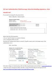
3.1.7 Firmware Upgrade<br />
This page allows users to upgrade firmware through a Web interface. In the System<br />
group, click the Firmware Upgrade option. You can see the following page then. Before<br />
you execute the firmware upgrade, please download the newest firmware from <strong>Draytek</strong>’s<br />
website (www.draytek.com) or FTP site (ftp.draytek.com) on the computer first.<br />
Firmware<br />
Apply<br />
Specify the location of the firmware file if you want to<br />
upgrade the firmware locally.<br />
After finished your selection, please click Apply to<br />
execute the firmware upgrade.<br />
Firmware Upgrade from a Console Port<br />
31<br />
<strong>VigorAccess</strong> <strong>A48</strong> User’s <strong>Guide</strong>
Firmware upgrade can be done from a console port, too. The following example was run<br />
on a Windows environment.<br />
1. Download the newest firmware from the DrayTek Website (www.draytek.com.tw)<br />
or FTP site (ftp.draytek.com) on your computer first.<br />
2. Connect the RJ45 connector of console cable to the console port on Vigor device and<br />
the DB9 connector of the console cable to the RS232 port on the PC.<br />
The default setting of the console port is “baud rate 57600, no parity, and 8 bit with<br />
1 stop bit.”<br />
3. Power on Vigor device, then press ENTER before the system reboots completely.<br />
4. Open Hyper Terminal on the PC. Now, the device can accept a TFTP download and<br />
will display the following message:<br />
<strong>VigorAccess</strong> <strong>A48</strong> User’s <strong>Guide</strong> 32
5. Type the path name of the firmware image and activate the TFTP Client from the<br />
PC to download the image. The corresponding message is shown as follows:<br />
firmware upgrade all <br />
6. Now in the Console you will find the following information. When Updating flash<br />
block at bfXXXXXX appears, it means the firmware is under downloading.<br />
7. When Start Upgrding appears, it means the firmware downloading has been<br />
completed.<br />
33<br />
<strong>VigorAccess</strong> <strong>A48</strong> User’s <strong>Guide</strong>
8. When Firmware Upgrade SUCCESSFUL appears, it means the firmware<br />
upgrading is finished. User should reboot it manual.<br />
3.1.8 Configuration Backup/Restore<br />
Most of the settings can be saved locally as a configuration file, and can be applied to<br />
another router. <strong>VigorAccess</strong> supports the restore and upload functions of the<br />
configuration files. Open System >> Configuration Backup/Restore. You can see the<br />
following page.<br />
<strong>VigorAccess</strong> <strong>A48</strong> User’s <strong>Guide</strong> 34
Restore<br />
Backup<br />
Click this button to restore the previous saved<br />
configuration file and apply to the device.<br />
Click this button the backup current configuration file.<br />
35<br />
<strong>VigorAccess</strong> <strong>A48</strong> User’s <strong>Guide</strong>
3.2 DSL Configuration<br />
This page is used for DSL related configuration. Line profile configures train rate, SNR,<br />
and etc. DSL show can display current DSL training status. Performance shows different<br />
type of error counts during Curr15Min/Curr1Day/Prev1Day. 有 修 改 , 請 幫 我 再 看 看<br />
3.2.1 Line Profile<br />
This page allows you to configure line profile parameters for the selected port. These<br />
parameters are defined in RFC 2662 of ADSL MIB. When a user wants to change these<br />
parameters, he/she can input the new value in the corresponding fields and click Apply<br />
button.<br />
Port Number<br />
Downstream/Upstream Rate<br />
Choose the port that you want to set. The port number<br />
includes 1 – 48.<br />
Configure DSL Downstream/Upstream transmit rate<br />
related parameter<br />
Intl Max TX Rate (bps)-Configure Maximum Transmit<br />
rate for 'Interleaved' channel, in bps.<br />
Intl Min TX Rate(bps)- Configure Minimum Transmit rate<br />
for 'Interleaved' channel, in bps.<br />
MaxIntl Delay(ms) - Configure Maximum Interleave<br />
Delay for this channel. Interleave delay applies only to the<br />
interleave channel and defines the mapping (relative<br />
spacing) between subsequent input bytes at the interleaved<br />
input and their placement in the bit stream at the<br />
interleaved output.<br />
<strong>VigorAccess</strong> <strong>A48</strong> User’s <strong>Guide</strong> 36
Fast Max TX Rate (bps) - Configure Maximum Transmit<br />
rate for 'Fast' channel, in bps.<br />
Fast Min TX Rate (bps) - Configure Minimum Transmit<br />
rate for 'Fast' channel, in bps.<br />
Downstream/Upstream SNR Margin<br />
DSL Downstream/Upstream (Singal to Noise Ratio)SNR<br />
related parameter:<br />
Target SNR Margin - the modem must achieve with a BER of<br />
10 to the power 7 or better to successfully complete<br />
initialization for Noise Margin.<br />
Max SNR Margin - Configure Maximum Signal/ Noise Margin<br />
for rate downshift or upshift.<br />
Min SNR Margin – Configure Minimum Signal/ Noise Margin<br />
for rate downshift or upshift.<br />
Rate Mode<br />
Type<br />
Trellis<br />
PsdMask Type<br />
Defines what form of transmit rate adaptation is<br />
configured on this device.<br />
It is used to configure the ADSL physical line mode.<br />
This parameter enables/disables trellis coding.<br />
This parameter selects the PSD mask option to be used.<br />
37<br />
<strong>VigorAccess</strong> <strong>A48</strong> User’s <strong>Guide</strong>
GS Standard<br />
Annex Type<br />
Dmt Config Mode<br />
Upstream Start Bin<br />
Upstream End Bin<br />
Downstream Start Bin<br />
Downstream End Bin<br />
This parameter defines what DSL capability will be use<br />
after training.<br />
This parameter defines what ADSL annex standard to be<br />
used.<br />
This parameter defines what frequency division mode to<br />
be used.<br />
The lowest bin number allowed for upstream signal.<br />
The highest bin number allowed for upstream signal.<br />
The lowest bin number allowed downstream signal.<br />
The highest bin number allowed for downstream signal.<br />
Downstream Minimal INP Parameter used to specify the minimum impulse noise<br />
protection for the downstream bearer channel.<br />
Upstream Minimal INP<br />
Interleave Depth<br />
Parameter used to specify the minimum impulse noise<br />
protection for the upstream bearer channel.<br />
Minimum interleaving depth supported by the customer's<br />
hardware.<br />
Downshift SNR Mgn<br />
Upshift SNR Mgn<br />
Min Downshift Time<br />
Min Upshift<br />
Configured Signal/ Noise Margin (SNR) for rate<br />
downshift. If the noise margin falls below this level, the<br />
modem should attempt to decrease its transmit rate.<br />
Configured Signal/ Noise Margin(SNR) for rate upshift. If<br />
the noise margin rises above this level, the modem should<br />
attempt to increase itis transmit rate.<br />
Determine the minimum time that the current margin is<br />
below Downshift SNR Mgn, before a downshift occurs.<br />
Determine the minimum time that the current margin is<br />
below upshift SNR Mgn, before a downshift occurs.<br />
<strong>VigorAccess</strong> <strong>A48</strong> User’s <strong>Guide</strong> 38
PM mode<br />
L0 Time<br />
L2 Time<br />
L2 ATPR<br />
L2 Min Rate<br />
L2 Entry Threshold Rate<br />
L2 Exit Threshold Rate<br />
L2 Entry Rate Min Time<br />
PM-related parameter used by the ATU-C to set the<br />
allowed link states.<br />
disable – No power management.<br />
l2enable - The ADSL link is active, but a low-power<br />
signal conveying background data is sent from the ATU-C<br />
to the ATU-R.<br />
l3enable - There is no signal transmitted on the line and<br />
thus no transmission of information is possible.<br />
This parameter represents the minimum time (in seconds)<br />
between an exit from the L2 state and the next entry into<br />
the L2 state.<br />
This parameter represents the minimum time (in seconds)<br />
between an entry into the L2 state and the first Power<br />
Trim (power saving) in the L2 state and between two<br />
consecutive Power Trims in the L2 State.<br />
This parameter represents the maximum aggregate<br />
transmit power reduction (in dB) that can be performed<br />
through a single Power Trim in the L2 state.<br />
This parameter specifies the minimum net data rate during<br />
the low power state (L2).<br />
This parameter allows the user to set a Current Traffic<br />
Rate threshold for transition from L0 to L2.<br />
This parameter allows the user to set a Current Traffic<br />
Rate threshold for transition from L2 to L0.<br />
This parameter allows the user to define the minimum<br />
interval of time that the current traffic rate should stay<br />
below the L2-entry Rate Threshold before transits to Low<br />
Power state.<br />
3.2.2 DSL Show<br />
DSL show displays current DSL status, down rate, up rate, current use standard and etc.<br />
39<br />
<strong>VigorAccess</strong> <strong>A48</strong> User’s <strong>Guide</strong>
Mode<br />
It is used to select the ADSL physical line mode. Fast and<br />
Interleaved represent different algorithms for DSL data<br />
transmission.<br />
DSL Name<br />
OpState<br />
Standard<br />
DownRate<br />
UpRate<br />
ATUC-SNR<br />
ATUC-PWR<br />
ATUC-ATN<br />
Display DSL line name.<br />
Display current operation status.<br />
Display current used DSL standard.<br />
Display current down rate.<br />
Display current up rate.<br />
Display the Noise Margin seen by this ATU with respect<br />
to its received signal in tenth dB in CO side.<br />
Display the total output power transmitted by this ATU in<br />
CO side.<br />
Display measured difference in total power transmitted by<br />
the peer ATU and the total power received by this ATU in<br />
CO side.<br />
<strong>VigorAccess</strong> <strong>A48</strong> User’s <strong>Guide</strong> 40
ATUR-SNR<br />
ATUR-PWR<br />
ATUR-ATN<br />
Refresh<br />
Display Noise Margin seen by this ATU with respect to its<br />
received signal in tenth dB in CPE side.<br />
Display the total output power transmitted by this ATU in<br />
CPE side.<br />
Display Noise Margin seen by this ATU with respect to its<br />
received signal in tenth dB in CPE side.<br />
Renew the current displayed information.<br />
3.2.3 Performance<br />
It shows error counts during current 15 minutes or current day or before.<br />
Port Number<br />
Type<br />
Choose the port that you want to see. The port number<br />
includes 1 – 48.<br />
The CPE (ATUR) or DSLAM (ATUC) side.<br />
Refresh<br />
Renew the current displayed information.<br />
3.3 PVC Configuration<br />
41<br />
<strong>VigorAccess</strong> <strong>A48</strong> User’s <strong>Guide</strong>
A permanent virtual circuit (PVC) is a virtual circuit established for<br />
repeated/continuous use between the same data terminal equipments (DTE). PVC can be<br />
established as an option to provide a dedicated circuit link between two facilities. PVC<br />
configuration is usually pre-configured by the service provider.<br />
3.3.1 PVC<br />
This page allows you to configure Virtual Path Identifier(VPI) and Virtual Circuit<br />
Identifier(VCI) for each PVC. The range for the Virtual Path Identifier is 0 to 255, and<br />
the range for the Virtual Circuit Identifier is 32 to 65535. The ATM Forum has reserved<br />
VCI identifiers 0 to 31 for control traffic.<br />
Bridge<br />
EOA<br />
AAL5<br />
PVC<br />
VPI<br />
VCI<br />
Display the number of the PVC profile.<br />
Display the EOA number of the PVC profile.<br />
Display ATM Adaptation Layer 5 (AAL5).It is used to<br />
send variable-length packets up to 65,535 octets in size<br />
across an Asynchronous Transfer Mode (ATM) network.<br />
Display the PVC number with DSL interface (x-y, x<br />
means DSL interface, y means PVC number)<br />
Display the value of Virtual Path Identifier.<br />
Display the value of Virtual Circuit Identifier.<br />
<strong>VigorAccess</strong> <strong>A48</strong> User’s <strong>Guide</strong> 42
MPOA<br />
Channel<br />
ATM<br />
DSL<br />
Create<br />
Delete<br />
Display the data encapsulation method used over the<br />
AAL5.<br />
Display the physical ADSL line mode.<br />
Display the ATM interface name.<br />
Display the DSL interface name.<br />
Click this button to create a new PVC profile.<br />
Click this button to delete the selected PVC profile.<br />
Creating a PVC<br />
Click Create to generate a new PVC profile. Below shows the detailed web page:<br />
DSL Port 1 – 48<br />
PVC 1 – 8<br />
MPoA<br />
Choose the number (DSL port) to make all the<br />
configuration will be applied to the created PVC.<br />
Use the drop down menu to choose the PVC number.<br />
Use the drop down menu to choose the data<br />
encapsulation method to be used over the AAL5.<br />
Channel<br />
It is used to select the ADSL physical line mode. Fast<br />
and Interleaved represent different algorithms for<br />
DSL data transmission.<br />
Mode<br />
Use the drop down menu to choose the type (protocol)<br />
for this PVC.<br />
Mac Profile<br />
It will be available when IPoA mode is selected. Use<br />
the drop down menu to choose a number of MAC<br />
43<br />
<strong>VigorAccess</strong> <strong>A48</strong> User’s <strong>Guide</strong>
3.3.2 Mac Profile<br />
profile. For more detailed of Mac Profile, please refer<br />
to 3.3.2.<br />
MAC address profile is a generic way for assigning MAC addresses for certain interfaces.<br />
The MAC address can be associated with a profile, and that profile can be attached to<br />
interface.<br />
Mac profiles used by IPoA / IPoE must not conflict with any of the Virtual Mac addresses<br />
configured in the system.<br />
Serial NO<br />
Profile ID<br />
MAC Address<br />
Create<br />
Delete<br />
Display the number of this profile.<br />
Display the identification number for this profile.<br />
Display the MAC address specified for this profile.<br />
Click this button to create a new MAC profile.<br />
Click this button to delete the selected MAC profile.<br />
Creating a Profile<br />
Click Create to generate a new VLAN profile. Below shows the detailed web page:<br />
Profile ID<br />
Mac Address<br />
Type the value as the identification number. The range is<br />
from 1 to 48.<br />
Type the Mac Address specified for this profile.<br />
3.4 Bridge Configuration<br />
Bridge configuration offers basic layer 2 switch configuration like VLAN create, delete,<br />
modify, Bridge port create, delete, modify and QoS profile create, delete, and modify.<br />
<strong>VigorAccess</strong> <strong>A48</strong> User’s <strong>Guide</strong> 44
3.4.1 VLAN<br />
VLAN is a group of hosts with a set of requirements that communicate when they are<br />
attached to the Broadcast domain, regardless of their physical locations. In IPDSLAM, it<br />
supports up to 512 VLAN at one time.<br />
Serial<br />
Display the number of the VLAN profile.<br />
Vlan id<br />
Display the ID number of the VLAN profile.<br />
Vlan name<br />
Display the name of the VLAN profile.<br />
Egress Port Display the egress port value for port 1- port 48.<br />
Untag Port Display the untag port value for port 1 - port 48.<br />
Bridging Mode<br />
Display the mode for the selected VLAN used.<br />
Edit<br />
Click this button to modify the existed VLAN profile.<br />
Create<br />
Click this button to create a new VLAN profile.<br />
Delete<br />
Click this button to delete the selected VLAN profile.<br />
Creating VLAN<br />
Click Create to generate a new VLAN profile. Below shows the detailed web page.<br />
Vlan id<br />
Vlan name<br />
Type the identification number of the VLAN profile. The<br />
range is from 1 to 4094.<br />
Type the name of the VLAN profile.<br />
45<br />
<strong>VigorAccess</strong> <strong>A48</strong> User’s <strong>Guide</strong>
Bridging Mode<br />
Choose the mode for the selected VLAN used.<br />
Restricted –Switching of traffic from one CPE to another<br />
CPE is prohibited. In case traffic coming from one CPE /<br />
downlink is meant for another CPE / downlink, it is<br />
dropped - effectively achieving VLAN isolation between<br />
CPEs / stacked DSLAMs.<br />
Unrestricted - Allow traffic passing between any two<br />
devices in the same VLAN.<br />
Residential - All traffic originating from the CPE ports<br />
are sent towards the uplink paths – without any destination<br />
address MAC lookup.<br />
Cross Connect - There is no learning and lookup, and<br />
there are at most two member ports for it.<br />
Egress Port<br />
Untag Port<br />
The set of ports are permanently assigned to the egress list<br />
for this VLAN by management.<br />
Choose the egress port to be applied under such VLAN<br />
profile.<br />
The set of ports should transmit egress packets for this<br />
VLAN, as untagged.<br />
Choose the untag port to be applied under such VLAN<br />
profile.<br />
Editing VLAN<br />
Click the radio button of the VLAN profile you want to edit. Next, click Edit to open it.<br />
Below shows the detailed web page.<br />
Note: Vlan ID and Vlan Name are fixed and cannot be modified. If you want to<br />
change it, delete the profile and create a new one.<br />
<strong>VigorAccess</strong> <strong>A48</strong> User’s <strong>Guide</strong> 46
3.4.2 Bridge<br />
This page is for Bridge configuration including, 802.1P, IGMP leaved mode, QoS<br />
configuration, and Max Unicast address.<br />
Bridge Port<br />
Display the number of the profiles that system offered.<br />
1 – 48 represents port 1 to port 48.<br />
Editing Bridge Profile<br />
Click the radio button of the profile you want to edit. Next, click Edit to open it. Below<br />
shows the detailed web page.<br />
47<br />
<strong>VigorAccess</strong> <strong>A48</strong> User’s <strong>Guide</strong>
Bridge Port<br />
Display the number of the profiles that you want to edit.<br />
Such number cannot be modified.<br />
802.1P The default ingress User Priority which can be configured<br />
by the user. The default value of this attribute can be 0.<br />
The large number means first priority.<br />
IGMP Mode<br />
This parameter specifies the IGMP Snooping Leave<br />
message processing mode for the port.<br />
Normal - the Leave message is forwarded to the Querier.<br />
Based on the Query received from Querier, the Leave<br />
processing is triggered.<br />
Fast - the port is immediately deleted from that multicast<br />
group on Leave message reception and then the Leave<br />
message is forwarded.<br />
Fast Normal – the Leave message is forwarded and the<br />
Leave processing is triggered immediately without waiting<br />
for any trigger from the Querier.<br />
ATM Qos<br />
It determines the process queue that the received frame is<br />
mapped to.<br />
UBR –all coming packets are dispatched with lowest<br />
priority queue.<br />
nrt – VBR - all coming packets are dispatched with high<br />
priority queue.<br />
CBR - all coming packets are dispatched with highest<br />
priority queue.<br />
Default –all coming packet are dispatched with proper<br />
priority queue according its priority field.<br />
<strong>VigorAccess</strong> <strong>A48</strong> User’s <strong>Guide</strong> 48
Max Unicast Addresses<br />
Configure max learned unicast addresses number. The<br />
default value is 64.Uplink port(193) default value is 256.<br />
Note: Bridge port is fixed and cannot be modified. If you want to change it, delete<br />
the profile and create a new one.<br />
3.4.3 Qos Profile<br />
A profile with a set of parameters is used to quantify the quality of service provided.<br />
Serial No<br />
Name<br />
PCR/SCR/MBS<br />
Edit<br />
Display the number of the profiles that system offered.<br />
1 – 48 represents port 1 to port 48.<br />
Display the QoS profile name for each port.<br />
Display the values of UBR, nrt-VBR, rt-VBR and CBR<br />
for PCR/SCR/MBS.<br />
PCR represents Peak Cell Rate.<br />
SCR represents Sustainable Cell Rat.<br />
MBS represents Maximum Burst Size.<br />
Click this button to modify the selected Qos profile.<br />
49<br />
<strong>VigorAccess</strong> <strong>A48</strong> User’s <strong>Guide</strong>
Editing QoS Profile<br />
Click the radio button of the profile you want to edit. Next, click Edit to open it. Below<br />
shows the detailed web page.<br />
Name<br />
PCR<br />
SCR<br />
MBS<br />
Display the name of the profile. You can retype the name<br />
to modify it.<br />
PCR means Peak Cell Rate. Values typed here can<br />
determine the process queue for the ratelimit of PCR value.<br />
UBR – The ratelimit of the lowest process queue.<br />
rt-VBR –The ratelimit of the high process queue.<br />
nrt-VBR –The ratelimit of the medium process queue.<br />
CBR –The ratelimit of the highest process queue.<br />
SCR means Sustainable Cell Rat. Values typed here can<br />
determine the process queue for the ratelimit of SCR value.<br />
UBR – The ratelimit of the lowest process queue.<br />
rt-VBR –The ratelimit of the high process queue.<br />
nrt-VBR –The ratelimit of the medium process queue.<br />
CBR –The ratelimit of the highest process queue.<br />
It means Maximum Burst Size. Values typed here can<br />
determine the process queue for the ratelimit of MBS<br />
value.<br />
UBR – The ratelimit of the lowest process queue.<br />
rt-VBR –The ratelimit of the high process queue.<br />
nrt-VBR –The ratelimit of the medium process queue.<br />
CBR –The ratelimit of the highest process queue.<br />
<strong>VigorAccess</strong> <strong>A48</strong> User’s <strong>Guide</strong> 50
Appendix A: Connectors<br />
A.1 RJ21 DSL Connector<br />
Connections made with two 50-pin champ cables are attached to the RJ21 interface on<br />
<strong>VigorAccess</strong>. Each cable terminates with a 50-pin Telco straight champ connector.<br />
Pin 1<br />
Pin25<br />
Pin 26 Male Pin 50<br />
Pin assignments between the Line and the PSTN splitter.<br />
Pin<br />
Number<br />
26<br />
1<br />
27<br />
2<br />
28<br />
3<br />
29<br />
4<br />
30<br />
5<br />
31<br />
6<br />
32<br />
7<br />
33<br />
8<br />
34<br />
9<br />
35<br />
10<br />
36<br />
11<br />
37<br />
12<br />
Wire Color<br />
White/blue<br />
Blue/white<br />
White/orange<br />
Orange/white<br />
White/green<br />
Green/white<br />
White/brown<br />
Brown/white<br />
White/gray<br />
Gray/white<br />
Red/blue<br />
Blue/red<br />
Red/orange<br />
Orange/red<br />
Red/green<br />
Green/red<br />
Red/brown<br />
Brown/red<br />
Red/gray<br />
Gray/red<br />
Black/blue<br />
Blue/black<br />
Black/orange<br />
Orange/black<br />
TIP/RING Port<br />
Number<br />
TIP<br />
RING<br />
TIP<br />
RING<br />
TIP<br />
RING<br />
TIP<br />
RING<br />
TIP<br />
RING<br />
TIP<br />
RING<br />
TIP<br />
RING<br />
TIP<br />
RING<br />
TIP<br />
RING<br />
TIP<br />
RING<br />
TIP<br />
RING<br />
TIP<br />
RING<br />
1 38<br />
13<br />
2 39<br />
14<br />
3 40<br />
15<br />
4 41<br />
16<br />
5 42<br />
17<br />
6 43<br />
18<br />
7 44<br />
19<br />
8 45<br />
20<br />
9 46<br />
21<br />
10 47<br />
22<br />
11 48<br />
23<br />
12 49<br />
24<br />
50<br />
25<br />
Pin<br />
Number<br />
Wire Color<br />
Black/green<br />
Green/black<br />
Black/brown<br />
Brown/black<br />
Yellow/blue<br />
Blue/yellow<br />
Black/gray<br />
Gray/black<br />
Yellow/orange<br />
Orange/yellow<br />
Yellow/green<br />
Green/yellow<br />
Yellow/brown<br />
Brown/yellow<br />
Yellow/gray<br />
Gray/yellow<br />
Violet/blue<br />
Blue/violet<br />
Violet/orange<br />
Orange/violet<br />
Violet/green<br />
Green/violet<br />
Violet/brown<br />
Brown/violet<br />
Violet/gray<br />
Gray/violet<br />
TIP/RING Port<br />
Number<br />
TIP 13<br />
RING<br />
TIP 14<br />
RING<br />
TIP 15<br />
RING<br />
TIP 16<br />
RING<br />
TIP 17<br />
RING<br />
TIP 18<br />
RING<br />
TIP 19<br />
RING<br />
TIP 20<br />
RING<br />
TIP 21<br />
RING<br />
TIP 22<br />
RING<br />
TIP 23<br />
RING<br />
TIP 24<br />
RING<br />
TIP<br />
RING<br />
25 is<br />
dummy<br />
51<br />
<strong>VigorAccess</strong> <strong>A48</strong> User’s <strong>Guide</strong>
A.2 Alarm Relay RJ45 Connector<br />
RJ45 jets provide connection with an external alarm device to the alarm relay connector,<br />
The alarm relays provide relay contact closures. If you connect the alarm relays, they<br />
transmit critical, major, and minor alarms to a separate, external alarm device. The alarm<br />
device uses a bell, light, or some other signal to alert people of the change in status. The<br />
alarm relay connector also provides one set of contacts for audible alarms and one set for<br />
visual alarms. The maximum contact rating is 30VDC, 2A 125VDC, 0.5A.<br />
Pin8<br />
Pin1<br />
The table below lists the pin assignments for backplane connector RJ45, the alarm relay<br />
connector.<br />
Pin Signal Description<br />
1 NC1 (NORMAL CLOSE CONTACT GROUP1)<br />
2 COM1 (COMMON CONTACT GROUP1)<br />
3 NO1 (NORMAL OPEN CONTACT GROUP1)<br />
4 NOT USED<br />
5 NOT USED<br />
6 NC2 (NORMAL CLOSE CONTACT GROUP2)<br />
7 COM2 (COMMON CONTACT GROUP2)<br />
8 NO2 (NORMAL OPEN CONTACT GROUP2)<br />
A.3 Alarm Port RJ45 Connector<br />
RJ45 jets provide connection with an external alarm device to the alarm connector. If you<br />
connect the alarm relays, they transmit critical, major, and minor alarms to a separate,<br />
external alarm device. The alarm device uses a bell, light, or some other signal to alert<br />
people of the change in status. The alarm relay connector also provides one set of contacts<br />
for audible alarms and one set for visual alarms. The maximum contact rating is 30VDC,<br />
2A 125VDC, 0.5A.<br />
Pin1<br />
Pin8<br />
<strong>VigorAccess</strong> <strong>A48</strong> User’s <strong>Guide</strong> 52
The table below lists the pin assignments for backplane connector RJ45, the alarm relay<br />
connector.<br />
Pin Signal Description<br />
1 RELAY NC RELAY NORMAL CLOSE CONTACT<br />
2 RELAY NO RELAY NORMAL OPEN CONTACT)<br />
3 RELAY COM (RELAY COMMON CONTACT)<br />
4 ALARM IN2 (ALARM INPUT CONTACT GROUP2)<br />
5 NOT USED<br />
6 ALARM IN1 (ALARM INPUT CONTACT GROUP1<br />
7 ALARM GND1 ALARM GND CONTACT GROUP1<br />
8 ALARM GND2<br />
ALARM GND CONTACT GROUP2<br />
A.4 RS232 Connector<br />
The RJ45 connection jet is used for CLI commands for system configurations and<br />
controlling functions in the <strong>VigorAccess</strong>. The jet is used for initialization of the<br />
<strong>VigorAccess</strong> during the preliminary installation. The “management cable”, as shown in<br />
Figure 1-15, converts the RJ45 to the RS232 interface. The RJ45 jet connects to a console<br />
interface in the <strong>VigorAccess</strong>, while the RS232 DB9 connecting to a console port on the<br />
computer.<br />
The default setting of the console port is “baud rate 9600, no parity, and 8 bit with 1<br />
stop bit (N81)”.<br />
The pin-out for this connector is shown below:<br />
RJ45 DB9 (Female) Signal<br />
No connection 1 CD<br />
3 2 TD<br />
6 3 RD<br />
7 4 DTR<br />
5 5 GND<br />
2 6 DSR<br />
8 7 RTS<br />
1 8 CTS<br />
No connection 9 RI<br />
53<br />
<strong>VigorAccess</strong> <strong>A48</strong> User’s <strong>Guide</strong>
A.5 Standard 10/100 Base-T Ethernet Interface Connector<br />
RJ45 jets provide 10/100 Base-T Ethernet interfaces. The interface supports MDI/MDIX<br />
auto-detection of either straight or crossover RJ45 cables. These cables are used on<br />
UP1,UP2/MGN interfaces.<br />
At 400 and 600 W the surface roughness was quite low (~15 2) and the coatings showed a<br />
mirror-like surface with a high brightness.<br />
RJ-45 Straight-through Cable Pin-outs<br />
RJ-45 Crossover Cable Pin-outs<br />
Signal Pin Pin Signal Signal Pin Pin Signal<br />
Tx+ 1 1 Tx+ Tx+ 1 1 Rx+<br />
Tx- 2 2 Tx- Tx- 2 2 Tx+<br />
Rx+ 3 3 Rx+ Rx+ 3 3 --<br />
-- 4 4 -- -- 4 4 --<br />
-- 5 5 -- -- 5 5 --<br />
Rx- 6 6 Rx- Rx- 6 6 Tx-<br />
- 7 7 - - 7 7 -<br />
- 8 8 - - 8 8 -<br />
<strong>VigorAccess</strong> <strong>A48</strong> User’s <strong>Guide</strong> 54
A.6 Standard 10/100/1000 Base-T Ethernet Interface<br />
Connector<br />
RJ45 jets provide 8P8C 10/100/1000 Base-T Ethernet interfaces. The interface supports<br />
MDI/MDIX auto-detection of either straight or crossover RJ45 cables. These cables are<br />
used on GE interfaces for subtending connection on Master and UP1, UP2/MGN port on<br />
Slave.<br />
RJ-45 Straight-through Cable Pin-outs (8P8C) RJ-45 Crossover Cable Pin-outs (8P8C)<br />
Signal Pin Pin Signal Signal Pin Pin Signal<br />
TP0+ 1 1 TP0+ TP0+ 1 1 TP1+<br />
TP0- 2 2 TP0- TP0- 2 2 TP1-<br />
TP1+ 3 3 TP1+ TP1+ 3 3 TP0+<br />
TP1- 4 4 TP1- TP1- 4 4 TP0-<br />
TP2+ 5 5 TP2+ TP2+ 5 5 TP3+<br />
TP2- 6 6 TP2- TP2- 6 6 TP3-<br />
TP3+ 7 7 TP3+ TP3+ 7 7 TP2+<br />
TP3- 8 8 TP3- TP3- 8 8 TP2-<br />
A.7 Contacting Your Dealer<br />
If the device you have still cannot work correctly after trying many efforts, please contact<br />
your dealer for further help right away. For any questions, please feel free to send e-mail<br />
to support@draytek.com.<br />
55<br />
<strong>VigorAccess</strong> <strong>A48</strong> User’s <strong>Guide</strong>