Good Practice Guide to Phase Noise Measurement ... - Sequanux
Good Practice Guide to Phase Noise Measurement ... - Sequanux
Good Practice Guide to Phase Noise Measurement ... - Sequanux

Create successful ePaper yourself
Turn your PDF publications into a flip-book with our unique Google optimized e-Paper software.
<strong>Measurement</strong> <strong>Good</strong> <strong>Practice</strong> <strong>Guide</strong> No. 68<br />
5 Quadrature method<br />
In the Quadrature System, two oscilla<strong>to</strong>rs at identical frequencies are used.<br />
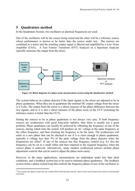
One of the oscilla<strong>to</strong>rs will be the source being tested and the other will be a reference source<br />
whose performance is known <strong>to</strong> be better than the source under test. The sources are<br />
combined in a mixer and the resulting output signal is filtered and amplified by a Low <strong>Noise</strong><br />
Amplifier (LNA). A Fast Fourier Transform (FFT) Analyzer or a Spectrum Analyzer<br />
typically measures the output from the mixer.<br />
Source<br />
under<br />
test<br />
Mixer<br />
Reference<br />
source<br />
Low<br />
pass<br />
filter<br />
LNA<br />
Spectrum analyzer<br />
or<br />
FFT analyzer<br />
Figure 14: Block diagram of a phase noise measurement system using the Quadrature method<br />
The system behaves as a phase detec<strong>to</strong>r if the input signals <strong>to</strong> the mixer are adjusted <strong>to</strong> be in<br />
phase quadrature. When they are in quadrature the nominal DC output voltage from the mixer<br />
is 0 Volts. The output from the mixer is a direct measure of the phase difference between the<br />
two signals, and so it is also a direct measure of the phase noise of the UUT (assuming the<br />
reference source is better than the UUT).<br />
Setting the sources <strong>to</strong> be in phase quadrature is not always very easy. If both frequency<br />
sources are synthesizers with good long-term stability, then there is usually not a great<br />
problem. <strong>Phase</strong> quadrature can usually be achieved by offsetting the frequency of one of the<br />
sources, during which time the system will produce an AC voltage at the same frequency as<br />
the offset frequency, and then resetting the frequency <strong>to</strong> be the same. The synthesizers will<br />
settle <strong>to</strong> a new phase that can be checked <strong>to</strong> see if it is close enough <strong>to</strong> phase quadrature,<br />
typically a voltage less than 5% of the peak voltage from the phase detec<strong>to</strong>r when the<br />
frequencies are offset 9 . If one of the sources has fine frequency control (e.g. 0.1 Hz) the<br />
frequency can be set <strong>to</strong> a small offset and then returned <strong>to</strong> the required frequency when the<br />
correct phase is achieved. Alternatively, many modern synthesized sources include phase<br />
adjustment controls that can be used <strong>to</strong> adjust the phase more easily.<br />
However, in the many applications, measurements are undertaken under less than ideal<br />
conditions, and a feedback system has <strong>to</strong> be used <strong>to</strong> maintain phase quadrature. The feedback<br />
system forms a phase locked loop that controls the frequency/phase of one of the oscilla<strong>to</strong>rs <strong>to</strong><br />
9 This assumes the signal is larger than any residual offsets from the phase detec<strong>to</strong>r. More on this can be found in the section on measurement<br />
uncertainty.<br />
21