DCX ISO/VDMA Catalog - Numatics
DCX ISO/VDMA Catalog - Numatics
DCX ISO/VDMA Catalog - Numatics

You also want an ePaper? Increase the reach of your titles
YUMPU automatically turns print PDFs into web optimized ePapers that Google loves.
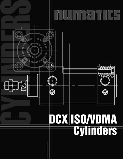
<strong>DCX</strong> <strong>ISO</strong>/<strong>VDMA</strong><br />
FEATURES<br />
• Removeable Rod Gland<br />
• Available with BSPP 1179 Ports<br />
• 32mm – 200mm Bore Sizes<br />
• Double Acting<br />
• Magnetic Thru-Wall Sensors<br />
• Cylindicator Ready Available<br />
• Adjustable Cushioning<br />
• To DIN/<strong>ISO</strong> 6431 and <strong>VDMA</strong> 24562<br />
• High Strength, Industion Hardened Steel<br />
(100,000 psi minimum yield) Piston Rod Has A<br />
Ground, Polished and Hard Chrome Plated Surface<br />
Providing Maximum Life Of Bushing And Seals.<br />
• Round Aluminum Cylinder Tubing With “Hard-Coat” ID<br />
• Seals Of Carboxilated Nitrite<br />
• Lifetime Lubrication<br />
• Designed To Meet <strong>DCX</strong> Specifications<br />
Conforms to BSPP 1179-1 Port, 228-1 Thread<br />
TECHNICAL DATA<br />
• Ports – G 1/8 to G 3/4 (1/8 NPTF to 3/4 NPTF)<br />
• Temperature – -20°C to +80°C (-4°F to 176°F)<br />
• Medium Temperature – max. 80°C (max. 176°F)<br />
• Operating Pressure – min. 0.8 bar/max 10 bar<br />
12 psig to 150 psig<br />
• Medium – Filtered, lubricated,<br />
or lubricated compressed air<br />
HOW TO ORDER<br />
D M 032 / 0220 000 A1<br />
SERIES<br />
D = Designed to meet<br />
<strong>DCX</strong> Specifications<br />
VERSION<br />
M = Double acting with magnetic<br />
G = Double acting with magnetic<br />
and cylindicator<br />
BORE DIAMETER IN mm<br />
(32-200)<br />
/ = BSPP 1179 N = NPTF Ports G = G Ports<br />
(position 1, 2, 3 & 4 except GG model = 2, 3 & 4)<br />
Cylinder stroke in mm<br />
DIMENSIONS<br />
CYLINDER MOUNTING ACCESSORIES<br />
000 = Basic no mount X0<br />
C01 = Foot bracket VC01<br />
CF2 = Front flange mount VC02<br />
CR2 = Rear flange mount VC02<br />
C03 = Foot bracket inside VC03<br />
C07 = Eye bracket VC07<br />
C08 = Clevis Bracket, wide clevis VC08<br />
C09 = Pivot ZC9<br />
(Standard; pivot in the center of cylinder<br />
tube, if position of pivot should be<br />
different, give dimension XI.)<br />
C13 = Oscillating joint bracket VC13<br />
C14 = Oscillating bracket, narrow clevis VC14<br />
CWB Mounting for Welker Bearing<br />
SPECIAL<br />
OPTIONS<br />
A1 = No Options<br />
RB = A1 and Rod Boot<br />
00 = Stainless Steel Rod<br />
SH = SU and Rod Boot<br />
*Dimension for DM model/Dimension for DG model.
OPTIONS<br />
<strong>DCX</strong> Model - Cylindicator Ready<br />
<strong>Numatics</strong> Actuator offers this series in a cylindicator ready version, proximity sensor, in addition to the<br />
magnet installed on the piston. This version incorporates two M6x1 tapped holes spaced 35mm apart for<br />
mounting the sensor at position #1. As well as having the hole for the cylindicator tapped 3/8" NPT and<br />
supplied with a port plug, regardless of cylinder port option.<br />
Probe Length: When ordering "G" version of this cylinder the following is a table of the probe lengths for<br />
the in-port proximity switches.<br />
Note: All cylinders utilize captive spacers to maintain standard probe lengths.<br />
Bore Size<br />
32mm – 80mm<br />
100mm<br />
125mm – 160mm<br />
200mm<br />
Probe Length<br />
26mm<br />
32mm<br />
52mm<br />
73mm<br />
Stroke to Go: These Cylindicator ready cylinders are designed to have stroke to go, which means that<br />
the proximity switch will activate before the cylinder reaches end of is stroke in either direction. The standard<br />
distances of stroke to go are shown in the following table.<br />
Bore Size<br />
32mm – 63mm<br />
80mm and up<br />
Rod End<br />
13mm ± 2mm<br />
14mm ± 2mm<br />
Cap End<br />
8mm ± 2mm<br />
12mm ± 2mm<br />
Rod Boot Information<br />
Specials option RB and SH add a rod boot to the cylinder, which requires an extra amount of rod extension<br />
to accommodate the rod boot.<br />
Required Extra Rod Extension:<br />
32mm-63mm Bore<br />
Extra Rod Extension = [.104 x Stroke (mm)] + 13mm<br />
80mm-200mm Bore<br />
Extra Rod Extension = [.059 x Stroke (mm)] + 13mm<br />
Note: The extra rod extension must be allowed for when determining mounting dimensions. For trunnion<br />
mounted cylinders this rod extension is added to the XI.<br />
Rod Boot Outside Dimensions:<br />
Below is a chart with the diameters of the rod boots for the <strong>ISO</strong>/<strong>VDMA</strong> cylinders.<br />
Bore Diameter (mm)<br />
32<br />
40<br />
50<br />
63<br />
80<br />
100<br />
125<br />
160<br />
200<br />
Rod Boot Outside Diameter<br />
2.25"<br />
2.25"<br />
2.63"<br />
2.63"<br />
3.38"<br />
3.38"<br />
3.75"<br />
4.13"<br />
4.13"<br />
Note: The Rod boot outside diameter on 32mm and 40mm cylinders is larger than the<br />
cylinder end cap square.
WORLD HEADQUARTERS<br />
USA<br />
<strong>Numatics</strong>, Incorporated<br />
46280 Dylan Drive<br />
Novi, Michigan 48377<br />
P: 1-888-<strong>Numatics</strong><br />
1-888-686-2842<br />
Canada<br />
<strong>Numatics</strong>, Ltd<br />
P: 519-452-1777<br />
Mexico<br />
<strong>Numatics</strong> de Mexico S.A. de C.V.<br />
P: 52-222-284-6176<br />
For a comprehensive listing of all <strong>Numatics</strong> production and distribution facilities worldwide, visit:<br />
www.numatics.com<br />
© <strong>Numatics</strong> Inc. 2008<br />
LT-G3<strong>Catalog</strong> 1.0<br />
10M-TGI-12/08