

Water hammer arrester - Caleffi
Water hammer arrester - Caleffi
Water hammer arrester - Caleffi

You also want an ePaper? Increase the reach of your titles
YUMPU automatically turns print PDFs into web optimized ePapers that Google loves.
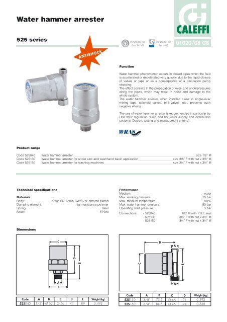
<strong>Water</strong> <strong>hammer</strong> <strong>arrester</strong><br />
525 series<br />
Product range<br />
REGI STERED BSI EN ISO 9001:2000<br />
Function<br />
Cert. n° FM 21654<br />
UNI EN ISO 9001:2000<br />
Cert. n° 0003<br />
CALEFFI<br />
01020/08 GB<br />
<strong>Water</strong> <strong>hammer</strong> phenomenon occurs in closed pipes when the fluid<br />
is accelerated or decelerated very quickly, due to the rapid closure<br />
of valves or taps or as a consequence of a circulation pump<br />
stopping.<br />
The effect consists in the propagation of over- and underpressures<br />
along the pipes, which may result in noise and damage to the<br />
whole system.<br />
The water <strong>hammer</strong> <strong>arrester</strong>, when installed close to single-lever<br />
mixing taps, solenoid valves, ball valves, etc., prevents such<br />
negative effects.<br />
The use of water <strong>hammer</strong> <strong>arrester</strong> is recommended in particular by<br />
UNI 9182 regulation “Cold and hot water supply and distribution<br />
systems. Design, testing and management criteria”.<br />
Code 525040 <strong>Water</strong> <strong>hammer</strong> <strong>arrester</strong> size 1/2” M<br />
Code 525130 <strong>Water</strong> <strong>hammer</strong> <strong>arrester</strong> for under sink and washhand basin application size 3/8” F with nut x 3/8” M<br />
Code 525150 <strong>Water</strong> <strong>hammer</strong> <strong>arrester</strong> for washing machines size 3/4” F with nut x 3/4” M<br />
Technical specifications<br />
Materials<br />
Body: brass EN 12165 CW617N, chrome plated<br />
Damping element: high resistance polymer<br />
Spring: steel<br />
Seals: EPDM<br />
Dimensions<br />
Code<br />
525040<br />
A<br />
1/2”<br />
B<br />
Ø 52<br />
C<br />
A<br />
B<br />
C<br />
Ø 46<br />
D<br />
D<br />
74<br />
ANTISHOCK<br />
E<br />
E<br />
89<br />
Weight (kg)<br />
0,492<br />
Performance<br />
Medium: water<br />
Max. working pressure: 10 bar<br />
Max. medium temperature: 90°C<br />
Max. water <strong>hammer</strong> pressure: 50 bar<br />
Operating start pressure: 3 bar<br />
Connections: - 525040 1/2” M with PTFE seal<br />
- 525130 3/8” F with nut x 3/8” M<br />
- 525150 3/4” F with nut x 3/4” M<br />
Code<br />
525130<br />
525150<br />
C<br />
A<br />
3/8”<br />
3/4”<br />
D<br />
B<br />
75,5<br />
84,5<br />
C<br />
Ø 46<br />
Ø 46<br />
A<br />
A<br />
B<br />
D<br />
71<br />
74<br />
Weight (kg)<br />
0,492<br />
0,538
The water <strong>hammer</strong> phenomenon<br />
In domestic water systems, water <strong>hammer</strong> phenomenon occurs<br />
when a pipe is closed rapidly by a device such as a single-lever<br />
mixing tap, solenoid valve, ball valve, etc.. The abruptness of the<br />
operation creates a perturbation in the water pressure which<br />
propagates along the pipe in the form of an overpressure wave.<br />
The perturbation starts from the check device, travels upstream,<br />
reflects against other devices or elbows in the pipe and returns<br />
downstream, damping progressively. The overpressure thus adds<br />
to the existing pressure in the pipe (as visible in the next page<br />
diagram), causing the following problems:<br />
- breakage of pipes, tanks and hoses<br />
- wear of seals, connecting welds and sanitary appliances<br />
- damage to shut-off, check and regulating equipments<br />
- high noise and powerful vibrations in both the pipes and the<br />
structures.<br />
The amount of the overpressure is influenced by numerous factors,<br />
which make the phenomenon difficult to reproduce under<br />
laboratory conditions:<br />
- equipment closing times<br />
- length, diameter and material of the pipe<br />
- velocity of the water.<br />
For the practical purpose of calculating the water <strong>hammer</strong><br />
overpressure, the following formula combines the most common<br />
variables in a domestic water system:<br />
2 · v<br />
Δp = –––––––– 1 · L<br />
g · t<br />
Δp = overpressure due to water <strong>hammer</strong> (m w.g.)<br />
v 1 = water velocity at time of closure start (m/s)<br />
L = length of pipe (m)<br />
g = acceleration of gravity (9,81 m/s 2)<br />
t = valve closing time (s)<br />
We can briefly indicate the physical significance of the “closing<br />
time” (better defined as “phase time”) with the following formula:<br />
2 · L<br />
t* = –––––––– (2)<br />
v2 t* = valve phase time (s)<br />
L = length of pipe (m)<br />
v2 = velocity of the perturbation propagation (m/s) (as a function of<br />
the medium, pipe material, inner diameter and thickness of<br />
the pipe).<br />
For mechanical devices such as single-lever mixing taps, solenoid<br />
valves, ball valves, etc., all closing times t ≤ t* are defined “sudden<br />
operations” and induce a water <strong>hammer</strong> in the pipe with an<br />
overpressure at the maximum intensity, which is the same for any<br />
operating time. On the other hand, a closing time t > t* is defined<br />
“slow operation” and causes a less intense water <strong>hammer</strong> effect,<br />
which may even be negligible.<br />
By setting t = t* within the formula (1), we obtain the maximum<br />
overpressure Δp value for the water <strong>hammer</strong> effect.<br />
This will be evident from the following graph.<br />
Δp<br />
Δp max.<br />
Overpressure<br />
Sudden<br />
operation<br />
(1)<br />
t*<br />
(phase time)<br />
formula valid for t > t*, [ see next definition ]<br />
Slow<br />
operation<br />
Closing time<br />
t<br />
Overpressure Δp (bar)<br />
Numerical example: pipe length 10 m, diameter equivalent to 1/2”,<br />
steel, copper and PE-X pipes with water velocity v 1 = 2 m/s. We<br />
give the values of the velocity of the perturbation propagation v 2,<br />
sudden operating times t* (phase time) and the overpressure Δp<br />
obtained with the formulas.<br />
L (m) v 1(m/s) v 2 (m/s) t* (ms) Δp (m w.g.) Δp (bar)<br />
Steel 10 2 1411 14,2 288 28,8<br />
Copper 10 2 1400 14,3 285 28,5<br />
PE-X 10 2 885 22,6 180 18<br />
Due to the greater stiffness of metal pipes, the velocity of the<br />
perturbation v 2 is greater than in plastic pipes and close to the<br />
velocity of sound in water (1420 m/s at 7°C). From these results, it<br />
is evident that plastic pipes for domestic water systems are more<br />
easily subject to water <strong>hammer</strong>, since they have a longer phase<br />
time t* than metal pipes. In practice, this means that closing<br />
operating times must be slower than in metal pipes. Although the<br />
overpressure values Δp for plastic pipes are lower than those for<br />
metal pipes (since they are less stiff, they partially dampen the<br />
water <strong>hammer</strong>), such overpressures can nonetheless stress the<br />
pipes beyond their resistance limit. Furthermore, in wall<br />
installations, the presence of a corrugated sheath or insulation<br />
influences the stiffness of plastic pipes, making the calculation of<br />
the water <strong>hammer</strong> even more complicated.<br />
From the example given, it is clear that the use of a water <strong>hammer</strong><br />
<strong>arrester</strong>, already useful for metal pipes, is even more advisable for<br />
domestic water systems with plastic pipes, especially if installed<br />
externally.<br />
The graph at the bottom of the page shows the influence of the<br />
various parameters on the overpressure in copper pipes at the time<br />
of the pipe closure. The three curves were obtained setting a<br />
closing time t equal to the phase time t* of a 100 m pipe of size<br />
20x1.<br />
We can draw the following conclusions:<br />
1) The longer the pipe, the greater the phase time t* and hence<br />
operations must be slower to prevent water <strong>hammer</strong> (formula<br />
(2)).<br />
2) For a given operating time t and medium velocity v 1, the longer<br />
the pipe, the greater the Δp caused by the operation<br />
(formula (1)).<br />
3) For a given medium velocity v 1 and length of pipe, larger<br />
diameters yield a slightly lower Δp (formula (1), but the<br />
difference is close to be negligible).<br />
4) For a given pipe length and operating time t, if the medium<br />
velocity v 1 increases, the Δp generated by the operation also<br />
increases (formula (1) and graph at foot of page).<br />
80<br />
70<br />
60<br />
50<br />
40<br />
30<br />
20<br />
10<br />
0<br />
1<br />
Copper pipe v 2 (m/s) t* (ms) 100 m pipe<br />
20x1 1393 143,5<br />
Overpressure in copper pipe 20x1<br />
Diagram obtained by setting the<br />
operation time t = t* = phase time<br />
of the 100 m pipe<br />
20x1 v1 = 1 m/s<br />
20x1 v1 = 2 m/s<br />
20x1 v1 = 5 m/s<br />
10<br />
Pipe length (m)<br />
100
Operating principle<br />
The <strong>Caleffi</strong> 525 series water <strong>hammer</strong> <strong>arrester</strong> is composed of a<br />
cylinder (1) divided into two chambers (2) and (3) by a piston with<br />
two o-ring seals (4). The closed chamber (2) contains air and acts<br />
as a damper due to the compressibility of the air. The open<br />
chamber (3) is connected directly to the pipe and fills with the<br />
system water. The water thrust on the piston is counteracted both<br />
by the air pressure variation in the chamber (2) and by the contrast<br />
spring (5) housed behind the piston in the air chamber.<br />
The oscilloscope graph reveals the following:<br />
- speed of the pressure increase<br />
- oscillatory character of the phenomenon<br />
- continuance of high pressure in the pipe even after the water<br />
<strong>hammer</strong><br />
- effectiveness of the water <strong>hammer</strong> <strong>arrester</strong>.<br />
2<br />
1<br />
3<br />
Construction details<br />
Reduced dimensions<br />
<strong>Water</strong> <strong>hammer</strong> <strong>arrester</strong>s are easy to install in the system, preferably<br />
in the vicinity of the shut-off devices which originate the<br />
overpressure to damp.<br />
Maintenance free<br />
Compared to pneumatic <strong>arrester</strong>s, <strong>Caleffi</strong> 525 series <strong>arrester</strong>s,<br />
since mechanical, are maintenance free.<br />
Foodsafe elastomers and other materials<br />
The elastomers used in the seals and the other materials comply<br />
with the compatibility requirements for use with potable water as<br />
required by WRAS certifications.<br />
Reference standards<br />
Article 15 of UNI 9182 (IT) “Cold and hot water supply and<br />
distribution systems. Design, testing and management criteria”,<br />
specifies that: “All cold and hot water distribution systems must be<br />
equipped with water <strong>hammer</strong> <strong>arrester</strong> of the mechanical (spring) or<br />
hydropneumatic (permanent or serviceable air cushion) type...”<br />
The installation of the water <strong>hammer</strong> <strong>arrester</strong> must also comply with<br />
the “Guidelines for the prevention and control of Legionnaire’s<br />
Disease”, as set out by the Ministry of Health and adopted by the<br />
Regional State Conference on 4.4.2000. The <strong>arrester</strong>s must be<br />
installed in such a way as not to create zones of stagnant water,<br />
which may be difficult to reach for the purposes of disinfection.<br />
5<br />
4<br />
Overpressure<br />
<strong>Water</strong> <strong>hammer</strong> <strong>arrester</strong> - effectiveness<br />
Reducer<br />
set<br />
pressure<br />
Certified performance<br />
The <strong>Caleffi</strong> 525 series water<br />
<strong>hammer</strong> <strong>arrester</strong> has been<br />
tested by KIWA (NL) to verify<br />
the conformity to the<br />
performance requirements for<br />
water <strong>hammer</strong> devices<br />
(reference standard BRL<br />
K632/02). The laboratory tests<br />
showed that the <strong>Caleffi</strong><br />
525 series provides a water<br />
<strong>hammer</strong> overpressure<br />
damping ratio of more than<br />
60%.<br />
Installation<br />
Sudden flow rate stop<br />
After the repeated oscillations, the<br />
pressure in the pipe remains high<br />
Registration of water <strong>hammer</strong> phenomenon<br />
Effect with water <strong>hammer</strong> <strong>arrester</strong><br />
BRL K632/02<br />
2000-06-02<br />
1999 Copyright, KIwa N.V.<br />
Niets uit deze uitgave mag<br />
verveelvoudigd en/of openbaar<br />
gemaakt worden door middel van<br />
druk, fotocopie, microfilm of op<br />
welke andere wijze dan ook, zonder<br />
voorafgaande schriftelijke<br />
toestemming van de uitgever.<br />
Het gebruik van deze<br />
Beoordelingsrichtlijn door derden,<br />
voor welk doel dan ook, is<br />
uitsluitend toegestaan nadat een<br />
schriftelijke overeen komst met Kiwa<br />
is gesloten waarin het gebruiksrecht<br />
is geregeld.<br />
Bindend verklaring<br />
Deze beoordelingsrichtlijn is door de<br />
directeur Certificatie en Keuringen<br />
van Kiwa bindend verklaard. per<br />
2 juni 2000.<br />
Time<br />
The <strong>Caleffi</strong> 525 series water <strong>hammer</strong> <strong>arrester</strong> must be installed as<br />
close as possible to the device which gives rise to the water<br />
<strong>hammer</strong> by suddenly shutting off the water flow, so as to damp the<br />
resulting overpressure as soon as possible. It may be installed<br />
horizontally, vertically or upside down.<br />
For better results, the installation of the <strong>Caleffi</strong> 525 series should<br />
include the following:<br />
- installation at the public network inlet of a pressure reducing<br />
valve to keep the system pressure at 3-4 bar, which is the optimal<br />
value for the operation of the water <strong>hammer</strong> <strong>arrester</strong> as well as<br />
the sanitary appliances;<br />
- reduction of the water velocity in the pipes. The water velocity<br />
directly affects the overpressure in case of rapid closure of the<br />
pipe.<br />
Erkenning<br />
Kiwa N.V<br />
Certificatie en Keuringen<br />
Sir Winston Churchill-laan 273<br />
Postbus 70<br />
2280 AB Rijswijk<br />
Tel. 070 - 41 444 00<br />
Tel. 070 - 41 444 20<br />
Internet www.kiwa.nl<br />
Beoordelingsrichtlijn<br />
voor het Kiwa productcertificaat voor<br />
<strong>Water</strong>slagdempers
The recommended solution is that shown below, where the water<br />
<strong>hammer</strong> <strong>arrester</strong> is installed either next to the end user service or at<br />
the main connection of a distribution manifold for a small group of<br />
domestic appliances.<br />
Installation recommendations<br />
The <strong>Caleffi</strong> 525 series water <strong>hammer</strong> <strong>arrester</strong>s are designed for<br />
single service installation (under washhand basins) or small groups<br />
of services, such as in a bathroom supplied by a domestic<br />
manifold. For larger scale water <strong>hammer</strong> problems, the solutions<br />
are different and must be designed to fit the particular case. One<br />
possible solution to water <strong>hammer</strong> may be to install an expansion<br />
vessel to act as an <strong>arrester</strong>.<br />
The traditional approach of installing water <strong>hammer</strong><br />
<strong>arrester</strong>s at the top of rising column, requires a review in<br />
the light of legislation about Legionnaire’s Disease.<br />
Although this solution was effective in attenuating water<br />
<strong>hammer</strong>, it is counterproductive in terms of system disinfection<br />
(both thermal and chemical) since it creates two types of hard to<br />
reach dead zones:<br />
- sections of pipe connecting the hot water rising pipes with the<br />
water <strong>hammer</strong> <strong>arrester</strong>s above the recirculation connections;<br />
- zones of stagnant water inside the water <strong>hammer</strong> <strong>arrester</strong>s<br />
themselves.<br />
SPECIFICATION SUMMARIES<br />
When installing the water <strong>hammer</strong> <strong>arrester</strong> under sinks and<br />
washhand basins, code 525130, create a space of 5-6 cm between<br />
the copper pipes and the threaded section of the shut-off valves.<br />
The radial connections enable water <strong>hammer</strong> <strong>arrester</strong> to be rotated<br />
to fit the available space.<br />
<strong>Water</strong> <strong>hammer</strong><br />
<strong>arrester</strong><br />
525 series<br />
<strong>Water</strong> <strong>hammer</strong> <strong>arrester</strong>. Threaded connections: 525040 1/2” M with PTFE seal on thread, 525130 3/8” F with<br />
nut x 3/8” M, 525150 3/4” F with nut x 3/4” M. Chrome plated brass body, high resistance polymer damping element, stainless<br />
steel spring, EPDM seals. Medium water. Maximum water <strong>hammer</strong> pressure 50 bar. Operating start pressure<br />
3 bar. Maximum working pressure 10 bar. Maximum medium temperature 90°C.<br />
We reserve the right to make changes and improvements to the products and related data in this publication, at any time and without prior notice.<br />
Dead<br />
zones<br />
INADVISABLE<br />
INSTALLATION<br />
CALEFFI<br />
CALEFFI S.P.A. · I · 28010 FONTANETO D’AGOGNA (NO) · S.R. 229, N.25 · TEL. +39 0322 8491 R.A. · FAX +39 0322 863723<br />
· www.caleffi.com · info@caleffi.com ·<br />
© Copyright 2008 <strong>Caleffi</strong>


