Installation Instructions - Durkopp Adler AG
Installation Instructions - Durkopp Adler AG
Installation Instructions - Durkopp Adler AG

You also want an ePaper? Increase the reach of your titles
YUMPU automatically turns print PDFs into web optimized ePapers that Google loves.
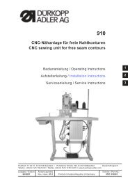
540-100-1<br />
CNC-Doppelsteppstich-Knopflochautomat<br />
CNC double lockstitch buttonholer<br />
Bedienanleitung / Operating <strong>Instructions</strong><br />
Aufstellanleitung / <strong>Installation</strong> <strong>Instructions</strong><br />
Serviceanleitung / Service <strong>Instructions</strong><br />
1<br />
2<br />
3<br />
Postfach 17 03 51, D-33703 Bielefeld Potsdamer Straße 190, D-33719 Bielefeld Deutsch/Englisch<br />
Telefon +49 (0) 5 21/ 59 25-00 Telefax+49(0)521/9252435 www.duerkopp-adler.com<br />
Ausgabe / Edition: Änderungsindex Teile-Nr.:/Part-No.:<br />
09/2009 Rev. index: 01.0 Printed in Federal Republic of Germany 0791 540001
Alle Rechte vorbehalten.<br />
Eigentum der Dürkopp <strong>Adler</strong> <strong>AG</strong> und urheberrechtlich geschützt. Jede, auch auszugsweise<br />
Wiederverwendung dieser Inhalte ist ohne vorheriges schriftliches Einverständnis der Dürkopp <strong>Adler</strong> <strong>AG</strong><br />
verboten.<br />
All rights reserved.<br />
Property of Dürkopp <strong>Adler</strong> <strong>AG</strong> and copyrighted. Reproduction or publication of the content in any manner,<br />
even in extracts, without prior written permission of Dürkopp <strong>Adler</strong> <strong>AG</strong>, is prohibited.<br />
Copyright 2009 - Dürkopp <strong>Adler</strong> <strong>AG</strong>
Foreword<br />
This instruction manual is intended to help the user to become familiar<br />
with the machine and take advantage of its application possibilities in<br />
accordance with the recommendations.<br />
The instruction manual contains important information on how to<br />
operate the machine securely, properly and economically. Observation<br />
of the instructions eliminates danger, reduces costs for repair and<br />
down-times, and increases the reliability and life of the machine.<br />
The instruction manual is intended to complement existing national<br />
accident prevention and environment protection regulations.<br />
The instruction manual must always be available at the machine/sewing<br />
unit.<br />
The instruction manual must be read and applied by any person that is<br />
authorized to work on the machine/sewing unit. This means:<br />
– Operation, including equipping, troubleshooting during the work<br />
cycle, removing of fabric waste,<br />
– Service (maintenance, inspection, repair) and/or<br />
– Transport.<br />
The user also has to assure that only authorized personnel work on the<br />
machine.<br />
The user is obliged to check the machine at least once per shift for<br />
apparent damages and to immediatly report any changes (including the<br />
performance in service), which impair the safety.<br />
The user company must ensure that the machine is only operated in<br />
perfect working order.<br />
Never remove or disable any safety devices.<br />
If safety devices need to be removed for equipping, repairing or<br />
maintaining, the safety devices must be remounted directly after<br />
completion of the maintenance and repair work.<br />
Unauthorized modification of the machine rules out liability of the<br />
manufacturer for damage resulting from this.<br />
Observe all safety and danger recommendations on the machine/unit!<br />
The yellow-and-black striped surfaces designate permanend danger<br />
areas, eg danger of squashing, cutting, shearing or collision.<br />
Besides the recommendations in this instruction manual also observe<br />
the general safety and accident prevention regulations!
General safety instructions<br />
The non-observance of the following safety instructions can cause<br />
bodily injuries or damages to the machine.<br />
1. The machine must only be commissioned in full knowledge of the<br />
instruction book and operated by persons with appropriate training.<br />
2. Before putting into service also read the safety rules and<br />
instructions of the motor supplier.<br />
3. The machine must be used only for the purpose intended. Use of<br />
the machine without the safety devices is not permitted. Observe all<br />
the relevant safety regulations.<br />
4. When gauge parts are exchanged (e.g. needle, presser foot, needle<br />
plate, feed dog and bobbin) when threading, when the workplace is<br />
left, and during service work, the machine must be disconnected<br />
from the mains by switching off the master switch or disconnecting<br />
the mains plug.<br />
5. Daily servicing work must be carried out only by appropriately<br />
trained persons.<br />
6. Repairs, conversion and special maintenance work must only be<br />
carried out by technicians or persons with appropriate training.<br />
7. For service or repair work on pneumatic systems, disconnect the<br />
machine from the compressed air supply system (max. 7-10 bar).<br />
Before disconnecting, reduce the pressure of the maintenance unit.<br />
Exceptions to this are only adjustments and functions checks made<br />
by appropriately trained technicians.<br />
8. Work on the electrical equipment must be carried out only by<br />
electricians or appropriately trained persons.<br />
9. Work on parts and systems under electric current is not permitted,<br />
except as specified in regulations DIN VDE 0105.<br />
10. Conversion or changes to the machine must be authorized by us<br />
and made only in adherence to all safety regulations.<br />
11. For repairs, only replacement parts approved by us must be used.<br />
12. Commissioning of the sewing head is prohibited until such time as<br />
the entire sewing unit is found to comply with EC directives.<br />
13. The line cord should be equipped with a country-specific mains<br />
plug. This work must be carried out by appropriately trained<br />
technicians (see paragraph 8).<br />
It is absolutely necessary to respect the safety<br />
instructions marked by these signs.<br />
Danger of bodily injuries !<br />
Please note also the general safety instructions.
Contents<br />
Page:<br />
Part 2: <strong>Installation</strong> <strong>Instructions</strong> Class 540-100-1<br />
1. Scope of delivery. ............................................. 3<br />
2. General and Transportation Safety<br />
2.1 Ringbolt ................................................... 3<br />
3. Equipment<br />
3.1 Structure of equipment ........................................... 4<br />
3.2 Available equipment ............................................ 5<br />
4. Optional equipment<br />
4.1 Positioningaids............................................... 7<br />
5. Assembling the sewing automat<br />
5.1 Makingthetabletop ............................................ 8<br />
5.2 Mounting the frame ............................................. 9<br />
5.3 Completion and mounting of table top .................................. 10<br />
5.4 Settingtheworkingheight......................................... 11<br />
5.5 Setting up the machine head ....................................... 11<br />
5.5.1 Lengthwise installation ........................................... 11<br />
5.5.2 Widthwiseinstallation............................................ 11<br />
5.5.3 Swivel device (optional) .......................................... 12<br />
5.5.4 Needle cooler (optional) .......................................... 13<br />
5.6 Mounting the control unit. ......................................... 15<br />
5.7 Mounting the waste container ....................................... 15<br />
5.8 Mounting the maintenance unit and the set value initiator ..................... 15<br />
5.9 Mounting the pedal and the traction rod ................................ 15<br />
2<br />
6. Electrical connection<br />
6.1 Plug connections at the multiple pin strip (4-fold) ........................... 16<br />
6.2 Plug connections at the multiple pin strip (15 fold) .......................... 17<br />
6.3 Potential compensation .......................................... 17<br />
6.4 Control connection to main switch .................................... 18<br />
7. Pneumatic connection<br />
7.1 Connecting the maintenance unit .................................... 19<br />
7.2 Connecting the waste container ..................................... 19<br />
8. Oil lubrication<br />
8.1 Filling the oil reservoir ........................................... 20<br />
9. Software installation<br />
9.1 Standard delivery .............................................. 21<br />
9.2 Softwareinstallation ............................................ 21<br />
9.2.1 General .................................................... 21<br />
9.2.2 Loading the program ............................................ 22<br />
9.2.3 Dongle-Update via Internet ........................................ 23<br />
9.3 Language setting .............................................. 23<br />
10. Sewing test ................................................. 24
8<br />
1<br />
2<br />
5<br />
11<br />
12<br />
4<br />
7<br />
9<br />
3<br />
10<br />
6
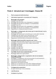
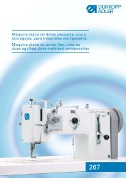
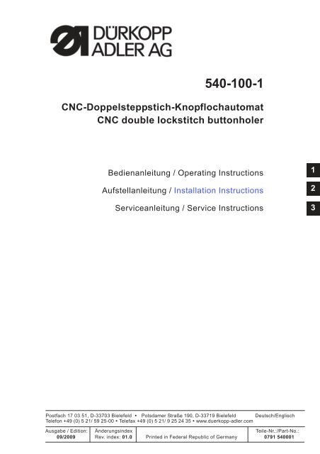
1. Scope of delivery<br />
The scope of delivery is dependent upon your order.<br />
Please check that all necessary parts are present.<br />
– 1 Machine head<br />
– 2 Control<br />
– 3 Maintenance unit<br />
– 4 Set value initiator<br />
– 5 Waste container<br />
– 6Tractionrod<br />
– 7Mainswitch<br />
– 8 Thread stand<br />
– Small parts in the accessories pack<br />
Only with delivery of frame (optional)<br />
– 9Frame<br />
– 10 Pedal<br />
– 11 Table top<br />
– 12 Drawer<br />
2<br />
2. General and Transportation Safety<br />
ATTENTION !<br />
The sewing automat 540 must only be installed by trained<br />
specialist staff !<br />
Transport securing devices<br />
If you have bought an assembled buttonholer; the following transport<br />
securing devices have to be removed:<br />
Securing tapes and wood battens at machine head, table and stand.<br />
2.1 Ring bolt<br />
The ring bolt makes it easier to lift the automat onto the frame. You can<br />
lift the automat using a ceiling crane or two people can lift the automat<br />
using a stable bar putting it through the ring bolt. The ring bolts are in<br />
the accessories pack.<br />
– Screw the ring bolt in the case lid of the machine head.<br />
– Lift the machine head onto the table plate.<br />
– Remove the ring bolt.<br />
3
3. Equipment<br />
3.1 Structure of Equipment<br />
Equipment: E 126/22<br />
Cutting<br />
Throat plate/basket<br />
1 = Cutting equipment with slit<br />
in the throat plate<br />
1 = blouses, shirts<br />
raised throat plate (0,6 mm); basket sole<br />
cross toothed<br />
2 = working clothes, heavy material<br />
flat throat plate; basket sole cross toothed<br />
3 = ties, cuffs<br />
flat throat plate; basket sole cross toothed,<br />
narrow<br />
4 = polo shirts<br />
flat throat plate; basket sole cross toothed,<br />
single side narrow, sewing basket steep sided<br />
5 = ladies outer wear, working clothes, sports and leisure<br />
wear with varying material thickness throat plate<br />
not raised;<br />
basket sole layered with Vulkollan foam<br />
to even out level differences<br />
6 = knitwear<br />
throat plate sharply raised (1,6 mm); basket sole<br />
toothed<br />
Stitch row width<br />
Sewing area and basket length<br />
3 = stitch row width max. 3 mm<br />
4 = stitch row width max. 4 mm<br />
6 = stitch row width max. 6 mm<br />
22 = Buttonhole length to max. 22 mm<br />
35 = Buttonhole length to max. 35 mm<br />
48 = Buttonhole length to max. 48 mm<br />
70 = Buttonhole length to max. 70 mm<br />
3.1.1 Sewing automat equipment components<br />
The components for up-to-date equipment can be found at<br />
www.duerkopp-adler.com in the Download area.<br />
4
3.2 Available equipment<br />
540 E 113/22 Sewing equipment for buttonholes in shirts and blouses,<br />
closely woven material, max. buttonhole width 3 mm, max.<br />
buttonhole length 22 mm.<br />
540 E 114/22 Sewing equipment for buttonholes in shirts and blouses,<br />
closely woven material, max. buttonhole width 4 mm, max.<br />
buttonhole length 22 mm.<br />
540 E 114/35 Sewing equipment for buttonholes in shirts and blouses,<br />
closely woven material, max. buttonhole width 4 mm, max.<br />
buttonhole length 35 mm.<br />
540 E 154/22 Sewing equipment for buttonholes in ladies outer wear,<br />
working clothes, sportswear and casual wear with cloth<br />
presser basket compensating the height differences, max.<br />
buttonhole width 4 mm, max. buttonhole length 22 mm.<br />
540 E 154/35 Sewing equipment for buttonholes in ladies outer wear,<br />
working clothes, sportswear and casual wear with cloth<br />
presser basket compensating the height differences, max.<br />
buttonhole width 4 mm, max. buttonhole length 35 mm.<br />
540 E 156/35 Sewing equipment for buttonholes in ladies outer wear,<br />
working clothes, sportswear and casual wear with cloth<br />
presser basket compensating the height differences, max.<br />
buttonhole width 6 mm, max. buttonhole length 35 mm.<br />
2<br />
540 E 133/22 Sewing equipment for buttonholes in collars of shirts and<br />
blouses and cuffs, with a narrow cloth presser basket,<br />
max. buttonhole width 3 mm, max. buttonhole length 22<br />
mm.<br />
540 E 134/22 Sewing equipment for buttonholes in collars of shirts and<br />
blouses and cuffs, with a special cloth presser basket , max.<br />
buttonhole width 4 mm, max. buttonhole length 22 mm<br />
540 E 146/22 Sewing equipment for buttonholes in Polo shirts, max.<br />
buttonhole width 6 mm, max. buttonhole length 22 mm.<br />
540 E 166/22 Sewing equipment for buttonholes in woven and knitted<br />
fabrics, max. buttonhole width 6 mm, max. buttonhole<br />
length 22 mm.<br />
540 E 166/35 Sewing equipment for buttonholes in woven and knitted<br />
fabrics, max. buttonhole width 6 mm, max. buttonhole length<br />
35 mm.<br />
540 E 126/22 Sewing equipment for buttonholes in working clothes,<br />
medium weight material, max. buttonhole width 6 mm, max.<br />
buttonhole length 22 mm.<br />
540 E 126/35 Sewing equipment for buttonholes in working clothes,<br />
medium weight material, max. buttonhole width 6 mm, max.<br />
buttonhole length 35 mm.<br />
540 E 126/48 Sewing equipment for buttonholes in working clothes,<br />
medium weight material, max. buttonhole width 6 mm, max.<br />
buttonhole length 48 mm.<br />
540 E 126/70 Sewing equipment for buttonholes in seat belt openings in<br />
stroller and infant safety seat, max. buttonhole width 6 mm,<br />
max. buttonhole length 70 mm.<br />
5
4. Optional equipment<br />
0540 211324 Cloth presser basket coated with Vulkollan (only for E<br />
113/22) and smooth material slider for buttonholes in shirts<br />
and blouses, prevents impressions in sensitive material.<br />
0540 211424 Cloth presser basket coated with Vulkollan (only for E<br />
114/22) and smooth material slide for buttonholes in shirts<br />
and blouses, prevents impressions in sensitive material.<br />
0540 211434 Cloth presser basket coated with Vulkollan (only for E<br />
114/35) and smooth material slide for buttonholes in shirts<br />
and blouses, prevents impressions in sensitive material.<br />
0540 590064 Swivel device for rapid change between lengthwise and<br />
widthwise installation, for a flexible mode of operation.<br />
0540 590014 Pneumatic needle cooler.<br />
9822 510026 Halogen tripod – sewing light incl. transformer, 1 x<br />
190-240V/12V sec. = 20 Watt (additionally needed are a<br />
table clamp and a connection kit).<br />
9822 510027 Table clamp (for sewing light 9822 510026).<br />
9870 001021 Sewing lamp connection kit (electrical connection for<br />
sewing light 9822 510026).<br />
6
4.1 Positioning aids<br />
Part No.<br />
0540 590144<br />
Spacing ruler with lateral guide for linen buttonholes in the front welt of<br />
men’s shirts and ladies’ blouses.<br />
2<br />
Part No.<br />
0540 590154<br />
Template positioning aid for collar tips, collar welts, cuffs, double cuffs<br />
and shirt flaps.<br />
The enclosed cardboard templates (5 pieces) are to be cut according<br />
to the form of the piece of clothing that is to be sewn. By turning the<br />
template only one template is needed for the sewing process, f. e. first<br />
sew the left collar welts and then the right collar welts with it.<br />
7
5. Assembling the sewing automat<br />
5.1 Making the table top<br />
If you are manufacturing your own table top then use the<br />
measurements in figure 1.<br />
Part number: 0700 054003<br />
1 Punch mark on the bottom<br />
2 Table plate bottom<br />
1<br />
2<br />
Fig. 1<br />
8
5.2 Mounting the frame<br />
– Mount the frame as shown in figure 2<br />
– To ensure a safe standing, all 4 feet have to have contact with the<br />
ground.<br />
– Screw the oil can onto the frame bar.<br />
2<br />
Fig. 2<br />
9
5.3 Completion and mounting of table top<br />
If you are mounting the table top yourself then please use the<br />
measurements in figure 2.<br />
– Screw cable channel 1 onto the table top.<br />
– Screw the mount for drawer 2 onto the table top.<br />
– Screw the main switch 3 onto the table top.<br />
– Fasten the table top onto the frame with four wood<br />
screws (B8 x 35).<br />
3<br />
1<br />
2<br />
Fig. 2<br />
10
5.4 Setting the working height<br />
The working height is adjustable.<br />
– Loosen both screws 5 on each of the frame bars.<br />
– Set the desired working height. Ensure that if possible both sides<br />
are pulled out or pushed in evenly.<br />
– Tighten both screws 5 again.<br />
5<br />
5.5 Setting up the machine head<br />
When taking the machine head out of the transport box, do not grab<br />
hold of the blocks, the cloth press plate or the control panel. Make sure<br />
that the oil reservoir is taped up to prevent that oil escapes during the<br />
set up.<br />
The machine head can be mounted lengthwise or widthwise. A swivel<br />
device is optionally available allowing lengthwise or widthwise<br />
installation to be changed quickly.<br />
2<br />
Fig. 1<br />
5.5.1 Lengthwise installation<br />
– Place the machine head on the table plate according to figure 1.<br />
– Feed all cables and hoses through the bore hole in the table top.<br />
– Set the machine head and screw it to the table top, according to<br />
figure 2, using 4 hexagonal screws .<br />
Fig. 2<br />
5.5.2 Widthwise installation<br />
– Place the machine head on the table plate according to figure 1.<br />
– Feed all cables and hoses through the bore hole in the table top.<br />
– Set the machine head and screw it to the table plate, according to<br />
figure 3, using 4 hexagonal screws .<br />
Fig. 3<br />
11
5.5.3 Swivel device (optional)<br />
– Loosen all cables and hoses, connected to the machine head<br />
under the table top.<br />
– Unscrew the fastening screws of the machine head under the table<br />
top.<br />
– Screw on the L-bracket 10 for the thread stand on the rear of the<br />
bed plate. Please use the provided screws 1 (2x), washer 2 (4x)<br />
und nuts 3 (2x).<br />
– Set aside the machine head (Fig. 1)<br />
Note:<br />
Make sure that the oil reservoir is taped up to avoid oil leak.<br />
– Fix the plastic fittings 4 with the nut 5 on the hinged plate 6.<br />
– Slide the felt 7 over the fitting 4.<br />
– Feed all cables and hoses through the fitting 4.<br />
For this purpose, the housing of the plug x120b must be<br />
dismantled.<br />
– Screw the hinged plate 6 under the bed plate.<br />
For this purpose, screw the threaded pin 8 (4x) on the rubber<br />
feet of the bed plate and secure the hinged plate using the falt<br />
nuts 9 (4x). After tightening the threaded pin, those must be flush<br />
with. They should in any case not be sticking out of the nuts.<br />
– Feed all cables and hoses through the bore hole in the table top.<br />
– Set the machine head with the swivel device on the bore holes of<br />
the table top.<br />
– Connect the cables and the hoses.<br />
– Screw the thread stand on the L-bracket 10.<br />
– Arrest the machine head lengthwise or widthwise using the set<br />
screw 11.<br />
Fig. 1<br />
12
5.5.4 Needle cooler (optional)<br />
Function<br />
The needle cooler operates parallel to the scissors pivoting cylinder.<br />
This means that the needle cooler is active while the scissors are<br />
swung out.<br />
21<br />
25<br />
23<br />
22<br />
24<br />
<strong>Installation</strong><br />
– Screw the throttle 21 into the tap hole of the scissors block.<br />
– Push the blower pipe 22 with its long arm into the throttle nozzle.<br />
The position of the air outlet can be varied by turning and pulling<br />
out the blower pipe.<br />
– Cut the pneumatic line 23 leading to the pivoting cylinder 5 cm<br />
underneath the arm outlet.<br />
– Insert the Y-piece.<br />
– Lay a new pneumatic line from the connection 24 on the scissors<br />
block to the Y-piece.<br />
– Shut the throttle 21 by turning the throttle screw 25 clockwise.<br />
– Switch the machine on.<br />
– Skip to the service menu.<br />
– Select the menu item T3.1.1 outputs. Activate the output Y2 for the<br />
swinging out of the scissors.<br />
– The throttle 21 of the needle cooler now receives compressed air.<br />
Adjust the desired air-flow by opening the throttle screw 25.<br />
– Quit the service menu by actuating the ESC key.<br />
– Test the function of the scissors swinging out by sewing a test<br />
seam.<br />
2<br />
Attention!<br />
Do not open the throttle completely. If the air-flow on the needle<br />
cooler gets too strong, it impairs the swinging out of the needle<br />
thread scissors.<br />
13
Notes:<br />
14
5.6 Mounting the control unit<br />
– Mount the control unit (DAC III) onto the table plate using 4 wood<br />
screws according to figure 2 on page 10. The side with the bushes<br />
for the motors (three bushes, one under the other) has to point to<br />
the right side.<br />
5.7 Mounting the waste container<br />
1<br />
2<br />
3<br />
– Remove cover 1 of the waste container.<br />
– Take the filter fleece 2 out of cover 1.<br />
– Screw cover 1 onto the table plate with two wood screws.<br />
– Refit the filter fleece 2 into the cover 1.<br />
– Refit the fleece clamping plate.<br />
– Finally stick the container 4 onto the cover 1.<br />
4<br />
2<br />
5.8 Mounting the maintenance unit and the set value initiator<br />
– Screw plate 5 onto the set value initiator 6.<br />
– Screw the set value initiator plate 6 to the maintenance unit<br />
6 L-bracket 7 on the cross strut of the frame 8 according to figure 4.<br />
5<br />
7<br />
5.9 Mounting the pedal and the traction rod<br />
8<br />
– Screw pedal 9 onto the frame strut 10.<br />
For ergonomic reasons the pedal center should be directly under<br />
the needle.<br />
– Fasten the traction rod 11 to the set value initiator 12 and the<br />
pedal 9.<br />
– Loosen screw 13 on the traction rod 11.<br />
– Set the length of the traction rod 11 so that pedal 9, without any<br />
pressure on it, has an inclination of about 10°.<br />
– Tighten screw 13 again.<br />
9<br />
12 13 11<br />
10<br />
15
6. Electrical connection<br />
6.1 Plug connections at the multiple pin strip (4-fold)<br />
1<br />
2<br />
3<br />
x20<br />
x30<br />
x40<br />
Connect the plug connectors of the linen buttonhole automat as<br />
follows:<br />
– 4-pole<br />
Plug connector 1 Sewing motor connector<br />
– 5-pole<br />
Plug connector 2 Stepping motor for the X-drive<br />
– 5-pole<br />
Plug connector 3 Stepping motor for Y-drive<br />
16
6.2 Plug connections at the multiple pin strip (15 fold)<br />
8<br />
4<br />
5<br />
6<br />
10<br />
7<br />
9<br />
Connect the plug connectors of the buttonhole automat,<br />
the set value initiator and the control panel as follows:<br />
2<br />
x140b<br />
x140t<br />
x300b<br />
x170<br />
x120b<br />
x110<br />
– REF-signals<br />
Light barrier plug /sensor<br />
on plug connector 4<br />
Note: 8-pole plug is coded.<br />
– Plug PWM (optional with the electronic thread<br />
tensioner)<br />
Magnetic plugs on plug connector 8<br />
Note: 8-pole plug is coded.<br />
– Encoder plug sewing motor<br />
Encoder plug signal sewing motor<br />
on plug connector 5<br />
– Control panel plug<br />
Control panel plug<br />
on plug connector 6<br />
– Plug I/O 1-8<br />
Operating device plug (pedal switch)<br />
via adapter 9 on plug connector 7<br />
– Test-Interface 10<br />
Dongle<br />
6.3 Potential compensation<br />
– Screw the potential compensation cable onto the<br />
control panel.<br />
11<br />
17
6.4 Control connection to main switch<br />
CAUTION !<br />
All work that needs to be carried out on the electrical installation of the<br />
linen buttonhole automat is only allowed to be carried out by an<br />
electrician or other qualified personal.<br />
The mains plug is to be unplugged!<br />
2 1 4 3<br />
5<br />
– Remove rotary knob 1.<br />
To do this loosen the screw 2 in the rotary knob.<br />
– Remove the cover 3 from the main switch.<br />
To do this use a screwdriver to unlock the latch in bore hole 4.<br />
– Place the cable from the control box in the cable channel.<br />
– Feed the cable into the main switch.<br />
– Connect the cable cores of the control box to the screws “T1" and<br />
“T2".<br />
– Connect the earth connection of the control box to the main switch.<br />
– Refit the cover to the main switch.<br />
– Refit the rotary knob and tighten it.<br />
18
7. Pneumatic connection<br />
7.1 Connecting the maintenance unit<br />
9<br />
– Connect the air hose 6 to the coupling.<br />
– Connect the hose nozzle 7 with an air hose onto its air supply<br />
connection.<br />
A pneumatic connection kit for the connection onto the existing air<br />
pressure network is available under order number: 0797 003031.<br />
– Connect the cable 9 to the pneumatic switch 8.<br />
6<br />
8<br />
7<br />
2<br />
CAUTION!<br />
The operating pressure is 6 bar. Check the maintenance unit to see<br />
whether 6 bar are indicated! If necessary, adjust the pressure on the<br />
maintenance unit to 6 bar.<br />
7.2 Connecting the waste container<br />
– Connect the air hose 8 (the thinner one of the two black air hoses)<br />
to the waste container.<br />
– Connect the hose 9 to the waste container. Hose 9 is used to<br />
exhaust cutting waste.<br />
8 9<br />
19
8. Oil lubrication<br />
Caution: Danger of injury !<br />
Oil can cause skin eruption.<br />
Avoid protracted contact with the skin.<br />
In the event of contact, thoroughly wash the affected area.<br />
ATTENTION !<br />
The handling and disposal of mineral oils is subject to legal<br />
regulations.<br />
Deliver used oil to an authorized collecting station.<br />
Protect your environment.<br />
Take care not to spill oil.<br />
Fill up the oil reservoirs exclusively with lubricating oil<br />
DA-10 or an equivalent oil with the following specification:<br />
– Viscosity at 40°C: 10 mm²/s<br />
– Ignition point: 150°C<br />
The oil can be bought at the sales points of DÜRKOPP ADLER <strong>AG</strong><br />
under the following parts numbers:<br />
250-ml-Container: 9047 000011<br />
1-Litre-Container: 9047 000012<br />
2-Litre-Container: 9047 000013<br />
5-Litre-Container: 9047 000014<br />
8.1 Filling the oil reservoir<br />
– Fill the oil reservoirs 1 and 2 through the hole in the inspection<br />
glasses.<br />
– The oil level has to be between min. and max.<br />
1 2<br />
20
9. Software installation<br />
9.1 Standard delivery<br />
With delivery of the sewing automat only the test software is installed<br />
in the control unit, which allows the loading of specific sewing software<br />
from the boot-dongle. The boot-dongle is in the machine head<br />
accessories pack.<br />
CAUTION!<br />
Only use the boot-dongle, that comes with the machine head.<br />
Using a dongle that contains the software of another machine class<br />
can cause damage to the sewing automat!<br />
9.2 Software installation<br />
9.2.1 General<br />
Loading a specific sewing software in the DACIII control unit is<br />
possible with the help of the “Programmed Dongle”. The “Programmed<br />
Dongle” has a label indicating the class and software version.<br />
Such a loading (booting) may be used in order to provide several<br />
DACIII control unit with a sewing software (first installation) or to install<br />
a newer machine software (update).<br />
With the delivery of the machine only the test software (allowing the<br />
loading of sewing software) is installed in the control unit.<br />
The test software offers no further functions. If the test software gets<br />
damaged during the loading process, it is no longer possible to load a<br />
software using a dongle.<br />
In such a case use a PC with a loader cable.<br />
The detailed procedure for this is described at the homepage of<br />
Dürkopp <strong>Adler</strong> <strong>AG</strong> “www.duerkopp-adler.com” among the section of<br />
“Download Area” and “Software”.<br />
2<br />
CAUTION !<br />
Turn off the main switch before connecting the dongle.<br />
21
9.2.2 Loading the program<br />
– Turn the machine off at the main switch.<br />
– Insert the dongle 2 into the socket X110 (TEST-Interface) 1 of the<br />
control unit (see pictures).<br />
– Switch on the main switch. The Software will be loaded. The<br />
loading process takes less than 60 seconds.<br />
– During the loading process do not remove the dongle and do not<br />
switch off the machine.<br />
– The machine proceeds with a warm start after the software is<br />
loaded.<br />
– Remove the dongle 2.<br />
– If necessary confirm the software version (caution: the machine<br />
software must match the machine class).<br />
The sub menu for the input of basket width and basket length (T1.4)<br />
will automatically be shown on the control panel. The length and width<br />
of the sewing basket has to be entered here. This setting only needs to<br />
be done with the initial installation.<br />
– Press the OK key.<br />
– Select the basket length of the sewing basket that is to be used<br />
with the arrow keys .<br />
If you are using your own sewing basket choose ´X´ as basket<br />
length and press the OK key. Set the desired value with the arrow<br />
keys . Select the position to be edited with the keys . Atthe<br />
end press the OK key.<br />
– With the arrow key select the menu point basket width.<br />
Press the OK key.<br />
– Select the basket length of the sewing basket with the arrow<br />
keys.<br />
If you are using your own sewing basket, choose ´X´ as basket<br />
width and press the OK key. Select the desired value with the<br />
arrow keys . Select the position to be edited with the keys .<br />
At the end press the OK key.<br />
– Press the ESC key. The main menu will be shown.<br />
CAUTION!<br />
Incorrect setting of the basket length and basket width causes<br />
damage to the sewing automat.<br />
– The machine is now ready for use.<br />
1<br />
2<br />
22
Important !<br />
During the loading process do not remove the dongle and do not switch<br />
off the machine (you will damage the Software)!<br />
Remove the dongle before the next switch-on, otherwise the sewing<br />
software will be reloaded again.<br />
9.2.3 Dongle-Update via Internet<br />
Dongles can be updated with programs available from the Dürkopp<br />
<strong>Adler</strong> homepage. Please open our homepage<br />
“www.duerkopp-adler.com” where you will find the relevant programs<br />
in the “Download” - section. Prerequisite is our auxiliary download<br />
software “Dongle Copy” which is available in the same section together<br />
with instructions for easy use.<br />
9.3 Language setting<br />
The menu language can only be changed after the basket length and<br />
basket width have been set during the initial installation of the sewing<br />
software. The choices are English (standard setting), German and<br />
parameter. To change the menu language proceed as follows:<br />
– Press the F key.<br />
The menu point input code will be shown.<br />
– Enter technician code 25483. Change the value with the arrow<br />
keys , select the position to be changed with the arrow keys<br />
. Confirm by pressing the OK key.<br />
– Select the menu point User Settings with the arrow keys<br />
. PresstheOK key<br />
– Select the menu point Language with the arrow keys . Press<br />
the OK key.<br />
– Select the desired language (German, English, Parameter) with the<br />
arrow keys .<br />
Press the OK key. A tick is shown behind the chosen language.<br />
– Press the ESC key to complete. The main menu will be shown.<br />
2<br />
23
10. Sewing test<br />
After completion of the assembly, a sewing test should be made.<br />
– Wind up bobbin thread (see operating instructions chapter 3.2)<br />
Caution: Danger of injury !<br />
Switch off main switch.<br />
Thread in the needle and bobbin thread only when the sewing automat<br />
is switched off.<br />
– Thread in the needle thread (see operating instructions<br />
chapter 3.1).<br />
– Place the bobbin and its housing (see operating instructions<br />
chapter 3.2 and 3.3).<br />
– Switch on main switch.<br />
The control unit is initialized.<br />
– Choose a workpiece to be processed.<br />
– Begin with a low speed at first (see operating instructions).<br />
Gradually increase the speed.<br />
– Check that the buttonhole meets the desired requirements.<br />
If not: Alter the thread tension (see operating instructions<br />
chapter 3.7).<br />
If needed please check also the setting instructions described<br />
in the service instructions.<br />
24