910 aufst - Durkopp Adler AG
910 aufst - Durkopp Adler AG
910 aufst - Durkopp Adler AG

You also want an ePaper? Increase the reach of your titles
YUMPU automatically turns print PDFs into web optimized ePapers that Google loves.
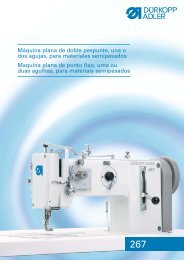
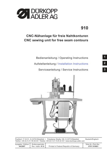
<strong>910</strong>CNC-Nähanlage für freie NahtkonturenCNC sewing unit for free seam contoursBedienanleitung / Operating InstructionsAufstellanleitung / Installation InstructionsServiceanleitung / Service Instructions123Postfach 17 03 51, D-33703 Bielefeld Potsdamer Straße 190, D-33719 Bielefeld Deutsch/EnglischTelefon +49 (0) 5 21/ 59 25-00 Telefax+49(0)521/9252435 www.duerkopp-adler.comAusgabe / Edition: Änderungsindex Teile-Nr.:/Part-No.:04/2007 Rev. index: 01.0 Printed in Federal Republic of Germany 0791 <strong>910</strong>001
Alle Rechte vorbehalten.Eigentum der Dürkopp <strong>Adler</strong> <strong>AG</strong> und urheberrechtlich geschützt. Jede, auch auszugsweiseWiederverwendung dieser Inhalte ist ohne vorheriges schriftliches Einverständnis der Dürkopp <strong>Adler</strong> <strong>AG</strong>verboten.All rights reserved.Property of Dürkopp <strong>Adler</strong> <strong>AG</strong> and copyrighted. Reproduction or publication of the content in any manner,even in extracts, without prior written permission of Dürkopp <strong>Adler</strong> <strong>AG</strong>, is prohibited.Copyright 2007 - Dürkopp <strong>Adler</strong> <strong>AG</strong>
ForewordThis instruction manual is intended to help the user to become familiarwith the machine and take advantage of its application possibilities inaccordance with the recommendations.The instruction manual contains important information on how tooperate the machine securely, properly and economically. Observationof the instructions eliminates danger, reduces costs for repair anddown-times, and increases the reliability and life of the machine.The instruction manual is intended to complement existing nationalaccident prevention and environment protection regulations.The instruction manual must always be available at the machine/sewingunit.The instruction manual must be read and applied by any person that isauthorized to work on the machine/sewing unit. This means:– Operation, including equipping, troubleshooting during the workcycle, removing of fabric waste,– Service (maintenance, inspection, repair) and/or– Transport.The user also has to assure that only authorized personnel work on themachine.The user is obliged to check the machine at least once per shift forapparent damages and to immediatly report any changes (including theperformance in service), which impair the safety.The user company must ensure that the machine is only operated inperfect working order.Never remove or disable any safety devices.If safety devices need to be removed for equipping, repairing ormaintaining, the safety devices must be remounted directly aftercompletion of the maintenance and repair work.Unauthorized modification of the machine rules out liability of themanufacturer for damage resulting from this.Observe all safety and danger recommendations on the machine/unit!The yellow-and-black striped surfaces designate permanend dangerareas, eg danger of squashing, cutting, shearing or collision.Besides the recommendations in this instruction manual also observethe general safety and accident prevention regulations!
General safety instructionsThe non-observance of the following safety instructions can causebodily injuries or damages to the machine.1. The machine must only be commissioned in full knowledge of theinstruction book and operated by persons with appropriate training.2. Before putting into service also read the safety rules andinstructions of the motor supplier.3. The machine must be used only for the purpose intended. Use ofthe machine without the safety devices is not permitted. Observe allthe relevant safety regulations.4. When gauge parts are exchanged (e.g. needle, presser foot, needleplate, feed dog and bobbin) when threading, when the workplace isleft, and during service work, the machine must be disconnectedfrom the mains by switching off the master switch or disconnectingthe mains plug.5. Daily servicing work must be carried out only by appropriatelytrained persons.6. Repairs, conversion and special maintenance work must only becarried out by technicians or persons with appropriate training.7. For service or repair work on pneumatic systems, disconnect themachine from the compressed air supply system (max. 7-10 bar).Before disconnecting, reduce the pressure of the maintenance unit.Exceptions to this are only adjustments and functions checks madeby appropriately trained technicians.8. Work on the electrical equipment must be carried out only byelectricians or appropriately trained persons.9. Work on parts and systems under electric current is not permitted,except as specified in regulations DIN VDE 0105.10. Conversion or changes to the machine must be authorized by usand made only in adherence to all safety regulations.11. For repairs, only replacement parts approved by us must be used.12. Commissioning of the sewing head is prohibited until such time asthe entire sewing unit is found to comply with EC directives.13. The line cord should be equipped with a country-specific mainsplug. This work must be carried out by appropriately trainedtechnicians (see paragraph 8).It is absolutely necessary to respect the safetyinstructions marked by these signs.Danger of bodily injuries !Please note also the general safety instructions.
IndexPage:Part 2: Installation Instructions cl. <strong>910</strong>1. Scope of delivery. ............................................. 32. General notes and securing devices ................................. 33. Mounting the stand and the control cabinet3.1 Tabletops................................................... 53.2 Mounting the parts of the stand ..................................... 53.3 Completingthetabletop.......................................... 63.4 Connecting the control box to the main switch ............................. 83.5 Mounting the stand and the reference value transmitter ....................... 93.6 Mounting the oil collector sump ...................................... 103.7 Adjustingtheworkingheight ....................................... 114. Mounting the sewing unit4.1 Mounting the oil pan ............................................ 124.2 Assemblyofthesewingunit........................................ 134.3 Mounting the control panel. ........................................ 144.4 Potential compensation .......................................... 154.5 Mounting the cover hood. ......................................... 1625. Connecting the plug connections to the control box5.1 Plug connections at the multiple pin strip (4-fold) ........................... 175.2 Plug connections at the multiple pin strip (15-fold) ......................... 185.3 Wiring..................................................... 196. Mounting the thread reel holder .................................... 197. Changing the sewing foot and the fabric clamps ......................... 208. Mounting the eye protection ...................................... 219. Oil lubrication9.1 Filling up oil. ................................................. 229.2 Oiling wicks and felt part (connecting rod) ............................... 239.3 Oiling the hook path. ............................................ 2410. Putting into operation10.1 Installationofthemachinesoftware................................... 2510.1.1 General notes ................................................ 2510.1.2 Loading the program ............................................ 2510.1.3 Dongle update via Internet. ........................................ 2610.3 Seamprogram................................................ 2710.4 Sewingtest ............................................. 2811. Optional equipment11.1 Sewinglamp................................................. 291
123410958762
1. Scope of deliveryThe scope of delivery is dependent on your order.Please check before the assembly whether all required parts areavailable.This description is valid for a sewing unit the individual components ofwhich are completely delivered by Dürkopp <strong>Adler</strong> <strong>AG</strong>.– 1 Machine head incl. oil panSetofparts(electric)with:– 2 Control panel– 5 Mains switch– 6 DAC controlDürkopp-<strong>Adler</strong> accessories with:– 3 Thread reel holder– Protectice cover (without illustration)– 8 Stand (optional)– 7 Pedal and rods (optional)– 4 Table top (optional)– 9 Oil collector sump– 10 Drawer (optional)22. General notes and securing devicesATTENTION !The sewing unit must only be assembled by trained specialist staff.Securing devicesIf you have bought an assembled sewing unit, the following securingdevices have to be removed:– Tapes and battens at machine head, table and stand.3
4 punch-marks fordrywall screwsPunch-marks from the underside1 x on this spot only4
3. Mounting the stand and the control cabinet3.1 Table topsThe cutouts of self-manufactured table tops must have the dimensionsindicated in the sketch.Caution: Risk of injury !The table tops must have the necessary load-bearing capacity andstability.3.2 Mounting the parts of the stand2321– Mount the individual parts of the stand as shown in the illustration.– Turn the adjusting screw 3 to ensure the stability of the stand.The stand must rest on the floor with all four feet.– Screw pedal 2 on stand strut 1.– Align pedal laterally.Shift the pedal sideways so that it is positioned centrally to the oilpan.The stand strut is provided with slotted holes for aligning the pedal.5
3.3 Completing the table top6 5 4 3 2 1– Place the table top on a worktop upside down.– Screw the main switch 6 on the underside of the table top on theleft.– Screw the cable duct 5 tight behind the main switch 6.– Screw the cable duct 2 tight to the left of the lead-through 1.– Put the connecting lead 4 in the cable duct.– Fasten the connecting lead 4 by means of strain relief 3.7– Mount the socket kit 7.– Connect the cable wires at the mains switch to the clamps L1 andL2 (see page (8).– Connect the protective switch in the mains switch.6
8– Place the control box 8 on the underside of the table top andposition it in such a way that the side with the four sockets points tothe left (towards the thread reel holder).– Screw the control box with four screws on the punch-marked spotat the underside of the table top.27
3.4 Connecting the control box to the main switchATTENTION !Work of every kind on the electric equipment of the sewing unit mustonly be carried out by electricians or correspondingly trainedpersonnel.The mains plug has to be pulled out!2 1 4 3– Take off the switching knob 1.For this purpose loosen the screw 2 in the knob.– Remove the cover 3 from the main switch.For this purpose unlock the locking bar in drill-hole 4 with ascrewdriver.– Run the cable from the control box into the cable duct.– Insertthecableinthemainswitch.– Connect the cable wires of the control box to the screws “T1" andT2".– Connect the protective conductor of the control box in the mainswitch.5– Put the cover on the mains switch again.– Put on the switching knob 1 and screw it tight.– Put the cover on the cable duct.8
3.5 Mounting the stand and the reference value transmitter312452– Put the stand on the table top and screw it tight.– Screw the set value initiator 1 with the mounting strap 2 to thestand brace.– Hook in the ball cups of the pedal bars 3 at the pedal and the setvalue initiator 1.– Screw the potential compensation cable 4 onto the mountingstrap 2.– Screw the potential compensation cable 4 of the set value initiatoronto the control unit using the screw 5.9
3.6 Mounting the oil collector sump1– Insert the holder for the oil collector sump in the drill-hole of thetable top.– Screw the oil collector sump 1 in.10
3.7 Adjusting the working height122The working height is adjustable between 750 and 950 mm (measuredup to the top edge of the table top).– Loosen the screws 1 at both spars of the stand.In order to avoid jamming pull out or push in both sides of the tabletop equally.The scales 2 at the outside of the spars serve as adjusting aid.– Tighten both screws 1.11
4. Mounting the sewing unit4.1 Mounting the oil pan2341– Lay the oil pan 1 on the table top 3, align it and screw it tightthrough the two through-bores 2 with two wood screws.– Push the screw (in the accessories) through the drill-hole 4 andtighten it with washer and nut.12
4.2 Assembly of the sewing unit4 3 2 18 7 6 5The small parts for setting up the sewing unit are included in theaccessories.– Place the sewing unit 1 on the oil pan 4.– Fasten the sewing unit on the left and on the right with the fixtures5 and 8.For this purpose screw the fixtures 5 and 8 tight with the screws 9,the sheets 11 and the counternuts 10.– Insert the machine head support 6 in the drill-hole of the table top.– Tilt the sewing unit sideways.– Run the connecting cables 2 under the table top through theopening 3.– Tilt the sewing unit back.2995810111013
4.3 Mounting the control panel4 3 2 1– Screw the control panel 4 on the sewing unit with angle 3.Lay rubber washers between the mounting angle of the controlpanel and the cast housing.– Connect the connecting cable 2 to the control panel.14
4.4 Potential compensation13 2– From the control 1 to the machine head 2– From the machine head 2 to the oil pan 3215
4.5 Mounting the cover hood3 2 14– Place the cover hood 2 on the fitting spring 4 from above.– Lay the cable 3 of the control panel in the gap 5 of the cover hoodbefore.– Screw the cover hood on the sewing unit with two screws throughthe drill-holes 1.3 516
5. Connecting the plug connections to the control box5.1 Plug connections at the multiple pin strip (4-fold)1232Connect the plug connections of the sewing unit as follows:– Plug connection 1 sewing motor plug (4-pole)– Plug connection 2 step motor for the X-drive (5-pole)– Plug connection 3 step motor for the Y-drive (5-pole)17
5.2 Plug connections at the multiple pin strip (15-fold)7612345Connect the plug connections of the sewing unit, the control panel andthe reference value transmitter as follows:– Plug of light barrier /sensorto plug connection 1 (REF-signals)Note: The 8-pole plug is encoded.– Plug of magnets to plug connection 6 (PWM)Note: The 8-pole plug is encoded.– Plug of encoder signal sewing motorto plug connection 2 (encoder sewing motor)– Plug of control panelto plug connection 3 (control panel)– Plug of control elements (pedal switch)via adapter 5 to plug connection 4(I/O 1-8)– Plug 7 for safe connection to the socket (SaveStop)18
5.3 Wiring2In order to make it possible to tilt the machine head back the cablesleading from the head through the opening in the table top either to themultiple pin strip (15-fold) at the control box or to the cable duct mustbe long enough. For this purpose the cables must be laid to form agreat bend 2 with the help of some cable clips.26. Mounting the thread reel holder– Insert the thread reel holder in the drill-hole of the table top andscrew it tight with nuts and washers.Mount and align the thread reel arms and the thread guides.The thread reel arms and the thread guides have to be positionedvertically one upon the other.19
7. Changing the sewing foot and the fabric clamps2 16 5 4 3The sewing unit <strong>910</strong> is delivered with two sewing feet.Caution: Risk of injury !Switchthemainswitchoff.Change the sewing equipment only with the main switch switched off.Changing the sewing foot– Unscrew screw 2.– Change sewing foot 1.– Insert screw 2 and tighten.Disassembling the upper fabric clamp– Unscrew screws 4.– Remove fabric clamp 3.Disassembling the lower fabric clamp– Unscrew screws 6.– Remove clamping plate 5.The assembly is done in reverse order.20
8. Mounting the eye protection4321Caution: Risk of injury !The sewing unit must not be operated without eye protection.2– Tighten the eye protection 1 at the sewing unit 4 with the fasteningangle 2 and the two screws 3.21
9. Oil lubricationCaution: Risk of injury !Oil can cause skin eruption.Avoid a longer contact with the skin.Wash yourself thoroughly after a contact.ATTENTION !The handling and disposal of mineral oils is subject to legalregulations.Deliver used oil to an authorized collecting station.Protect your environment.Be careful not to spill any oil.Fill up the oil reservoirs exclusively with lubricating oil DA-10 or anequivalent oil with the following specification:– Viscosity at 40° C: 10 mm 2 /s– Ignition point: 150° CDA-10 can be bought at the sales points ofDÜRKOPP-ADLER <strong>AG</strong> under the following parts numbers:250 ml container: 9047 0000111-Litre container: 9047 0000122-Litre container: 9047 0000135-Litre container: 9047 0000149.1 Filling up oil124 3Oil reservoir for lubricating the sewing unit– Fill up oil through the drill-holes 1 and 4.– Check the oil level at the inspection glasses 2 and 3.The oil level must be above the red mark of both inspectionglasses.22
9.2 Oiling wicks and felt part (connecting rod)2 1ATTENTION !When assembling the machine and after longer idle times the wicksand the felt part 1 have to be soaked with some oil.2– Screw off the bobbin plate.– Soak felt 1 and 2 with oil.– Put on the bobbin plate and tighten.23
9.3 Oiling the hook path21Oiling the hook path– Flap down the hook cover.– Give a drop of oil between driver 2 and path 1.– Close the hook cover.ATTENTION !When assembling the machine and after longer idle times the hookpath and the connecting rod have to be lubricated.Caution: Risk of injury !Switchthemainswitchoff.Lubricate the sewing unit only when it is switched off.24
10. Putting into operation10.1 Installation of the machine software10.1.1 General notesWith the help of the “dongle with program” a specific sewing softwarecan be loaded on a DACIII control. The “dongle with program” ismarked by a label indicating the machine class and the softwareversion.Such a loading process (booting) can e.g. be used to provide anindividual DACIII control with a sewing software (first installation) or toload a new sewing software (update).When delivering an individual control this is provided with a checksoftware only enabling the loading of a sewing software. The checksoftware does not allow further functions. If this check software isdestroyed by an incorrect loading process, it will not be possible anymore to load a software by means of a dongle. In this case a PC with aloader cable has to be used.Please find a detailed description of the procedure on the homepage ofDürkopp <strong>Adler</strong> <strong>AG</strong> “www.duerkopp-adler.com” under the category“Download Area” and “Software”.ATTENTION !Switch off the main switch before connecting the dongle!210.1.2 Loading the program– Switchthemainswitchoff.– Plug the dongle 2 in the bushing X110 (dongle) 1 of the control(see illustrations on page 26).– Switch the main switch on. The software is loaded. The loadingprocess will last less than 60 seconds.Note !Do not pull out the dongle or switch the machine off during the loadingprocess (otherwise the software will be destroyed)!– After loading the software the machine will make a warm start.– The basic screen appears.25
– Pull the dongle 2 out now.ATTENTION !The software must be compatible with the machine class.If the software version does not correspond to the machine class, donot confirm.Switch the machine off and repeat the loading process with the correctsoftware version.2110.1.3 Dongle update via InternetThe dongle can be updated via the Internet. For this purpose call upthe homepage of Dürkopp <strong>Adler</strong> <strong>AG</strong> “www.duerkopp-adler.com”. Underthe category “Download Area” and “Software” you will find thedownload service programs and the corresponding machine software.The instructions available on this page describe the exact procedurefor updating the dongle.26
10.2 Seam programIf no seam program is stored in the control, the following message willbe indicated when the sewing unit is switched on for the first time:– Press the “ESC” key.The main menu appears.– Create a new seam program by teach-in or load a seam programfrom the dongle (see operating instructions).227
10.3 Sewing testAfter finishing the assembly work a sewing test should be made.– Plug the mains plug in.– Wind up the bobbin thread (see operating instructions chapter 7.5)Caution: Risk of injury!Switchthemainswitchoff.Thread in the needle thread and the bobbin thread only with the sewingmachine switched off.– Thread in the needle thread (see operating instructionschapter 7.1).– Insert the bobbin thread winder (see operating instructionschapter 7.6).– Switchthemainswitchon.The control is initialised.– Select the material to be processed.– Make the sewing test first at low speed and then at continuouslyincreasing speed.– Check whether the seam pattern corresponds to the desiredrequirements.If the requirements are not met, alter the thread tensions (seeoperating instructions chapters 7.2 and 7.7).If necessary, also check the adjustments indicated in the serviceinstructions and correct them, if required.– Check the oil level at both inspection glasses during the operationof the sewing unit.28
11. Optional equipment11.1 Sewing lamp3 2 1For the sewing unit <strong>910</strong> the sewing lamp 1 (order no.9822 510026) and the table clamp 3 (order no. 9822 510027) areavailable.– Clamp the sewing lamp on the table top 2.– Push the plug in the socket under the table top.229
Note:30