
Create successful ePaper yourself
Turn your PDF publications into a flip-book with our unique Google optimized e-Paper software.
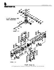
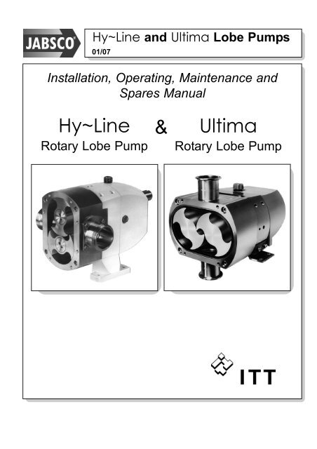
Hy~Line and Ultima <strong>Lobe</strong> <strong>Pumps</strong><br />
01/07<br />
Installation, Operating, Maintenance and<br />
Spares Manual<br />
Hy~Line<br />
Rotary <strong>Lobe</strong> Pump<br />
&<br />
Ultima<br />
Rotary <strong>Lobe</strong> Pump
Hy~Line and Ultima <strong>Lobe</strong> <strong>Pumps</strong><br />
01/07<br />
Contents<br />
1. INTRODUCTION<br />
1.01 Safety<br />
1.02 Principle of operation<br />
1.03 Operating conditions<br />
1.04 Model numbering system<br />
1.05 Inspection upon receipt<br />
2. INSTALLATION<br />
2.01 Operating limitations<br />
2.02 Location & Positioning<br />
2.03 Drives<br />
2.04 Baseplate<br />
2.05 Guards and safety<br />
2.06 Electrical<br />
2.07 Pipework<br />
2.08 Enlarged rectangular inlet<br />
2.09 Temperature control jackets<br />
2.10 Seals and flushing<br />
2.11 Seal materials<br />
2.12 End Cover relief valve<br />
2.13 End cover barrier<br />
2.14 Overload protection<br />
3. LUBRICATION<br />
4. START UP & ROUTINE CHECKS<br />
4.01 Start up<br />
4.02 Daily Checks<br />
4.03 Weekly Checks<br />
4.04 Monthly Checks<br />
4.05 Six Monthly Checks<br />
4.06 Annual Checks<br />
5. CLEANING AND STERILIZING<br />
5.01 Cleaning in place (CIP) & Manual<br />
cleaning<br />
5.02 Sterilizing in place (SIP)<br />
6. INSPECTION AND REPAIR<br />
6.01 End cover<br />
6.02 Rotors<br />
6.03 Mechanical shaft seals - single primary<br />
6.04 Mechanical shaft seals - single flushed<br />
6.05 Mechanical shaft seals - double<br />
6.06 Seal housings<br />
6.07 Single o-ring seal<br />
6.08 Double o-ring seal<br />
6.09 Multi-Lip seal<br />
6.10 Rotor case<br />
6.11 Rotor clearance - checking &<br />
adjustment<br />
6.12 End cover relief valve<br />
6.13 Thermal jacket –end cover<br />
6.14 Thermal jacket –pump head<br />
6.15 Thermal jacket –rotor case<br />
6.16 Bearing housing - inspection & repair<br />
6.17 Gearbox shafts and gears<br />
6.18 Bearing set-up and pre-load<br />
7. MODEL NUMBER BUILD CODE<br />
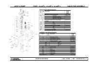
8. PARTS LIST AND EXPLODED<br />
DIAGRAMS<br />
8.01 Parts List<br />
8.02 Hy~Line Exploded Diagram<br />
8.03 Ultima Exploded Diagram<br />
8.04 Hy~Line 3 Size Sectional View<br />
8.05 Options & Extras - Sectional Views<br />
DECLARATION OF INCORPORATION<br />
Warranty: All products of the company are sold and all services of the company are offered subject to the company’s warranty and terms and conditions of sale, copies of which will be furnished upon request.<br />
The information provided herein is for guidance only, it does not constitute a guarantee of the performance or specification of any individual product or component.<br />
©Copyright 2000 ITT Industries - Jabsco 43010-0201
Hy~Line and Ultima <strong>Lobe</strong> <strong>Pumps</strong><br />
01/07<br />
Page 1<br />
Jabsco Hy~Line and Ultima<br />
Rotary <strong>Lobe</strong> <strong>Pumps</strong><br />
Installation Operating and<br />
Maintenance Manual<br />
1. INTRODUCTION<br />
Hy~Line and Ultima are positive<br />
displacement rotary lobe pumps designed to<br />
pump delicate, viscous and particle-laden<br />
fluids as well as thin liquids which require an<br />
all stainless steel pump. They share many<br />
common features but the construction of<br />
Ultima differs to provide an exceptionally<br />
high standard of hygiene and cleanability.<br />
This entire manual applies to both pump<br />
ranges, except:<br />
It is essential that anyone who will install,<br />
operate, or be involved with this equipment<br />
shall read the whole of this manual before<br />
installing the pump, as it contains<br />
important safety information. Failure to<br />
follow these instructions could result in<br />
damage to the pump or injury to yourself<br />
or other people.<br />
Adherence to the procedures and<br />
specifications outlined in the following<br />
chapters will assist in providing economical<br />
and reliable operation throughout the life of<br />
the pump.<br />
If service or repair other than that described<br />
in this manual should become necessary,<br />
contact your supplier for assistance.<br />
Any pump returned to the supplier for any<br />
reason must be fully cleaned and<br />
decontaminated and accompanied by<br />
details of what fluids have been pumped,<br />
including full Health and Safety information<br />
(MSDS sheets) if any of those fluids are<br />
hazardous.<br />
All figures in brackets ( ) throughout this<br />
manual refer to the component key numbers<br />
used on the cross-sectional drawings and<br />
the spare parts lists.<br />
1.01 SAFETY<br />
Throughout this manual your attention is<br />
drawn to certain procedures which must be<br />
followed to ensure safe operation and<br />
servicing of this product.<br />
DO NOT ignore safety instructions.<br />
DO NOT remove, by-pass or tamper<br />
with safety devices.<br />
DO NOT use this equipment if the<br />
end cover (122) is removed, guards<br />
are missing or inlet & outlet<br />
pipework is not connected.<br />
DO NOT forget the hazards of<br />
moving parts, high fluid pressure,<br />
extremes of temperature,<br />
hazardous liquids, electricity.<br />
Always isolate and lock-out pump<br />
drive motor before inspecting or<br />
servicing pump.
Hy~Line and Ultima <strong>Lobe</strong> <strong>Pumps</strong><br />
01/07<br />
Page 2<br />
1.02 PRINCIPLE OF OPERATION<br />
Hy~Line and Ultima pumps have 2 rotors<br />
which turn in opposite directions. Fluid<br />
enters the pump from the inlet port and fills<br />
the space between the rotors. This fluid is<br />
carried around the outside of the rotors and<br />
is forced out of the discharge port as the<br />
rotor lobes mesh together see Figure 1.<br />
Each rotor is supported on a shaft and when<br />
the pump is running within its operating<br />
limits, the rotors never touch the inside of<br />
the rotor case, or each other.<br />
Figure 1<br />
Principle of<br />
Operation<br />
(Showing<br />
Vertical<br />
Mounting)<br />
1.03 OPERATING CONDITIONS<br />
Hy~Line and Ultima pumps are designed<br />
using modern design techniques and<br />
manufactured from high quality materials.<br />
However, there are certain limitations to the<br />
operating conditions of the pump to ensure<br />
long life and trouble-free running. During<br />
pump selection and specification these<br />
limitations are taken into account and must<br />
not be exceeded.<br />
Every pump is supplied with a Performance<br />
Data Sheet which gives details of these<br />
limitations. These are:-<br />
Maximum Pressure<br />
Maximum Temperature<br />
Maximum Viscosity<br />
Maximum Particle Size<br />
Maximum Speed<br />
Maximum Input Shaft Torque<br />
Maximum Input Shaft Radial Load<br />
These limitations and performance<br />
characteristics vary from one pump size to<br />
another, and from one pump specification to<br />
another within the same pump size.<br />
Take particular care over the following:-<br />
Materials: Ensure that all the fluids to be<br />
pumped, including cleaning and sterilizing<br />
agents, are compatible with the materials<br />
from which the pump is constructed.<br />
See section 2.10 for details of shaft or seal<br />
types and section 2.11 for alternative seal<br />
materials, i.e. seal faces and elastomers.
Hy~Line and Ultima <strong>Lobe</strong> <strong>Pumps</strong><br />
01/07<br />
Page 3<br />
Hy~Line and Ultima pumps can be used for<br />
duties other than those for which each pump<br />
was originally selected but the new<br />
application must be checked against the<br />
Performance Data Sheet to ensure safe and<br />
reliable operation. Unless you have<br />
experience in the use of this Data Sheet, we<br />
strongly recommend that, if a change of duty<br />
is required, you contact the distributor who<br />
supplied the unit or the manufacturer.<br />
Change of duty means changing any of the<br />
parameters listed above.<br />
1.04 MODEL NUMBERING SYSTEM<br />
A metal plate is fixed to the pump showing<br />
model number and serial number.<br />
a) Remove packing material from<br />
container and check contents against<br />
packing list. Look carefully for small<br />
parts and special tools included.<br />
b) Check the pump for any physical<br />
damage sustained in shipping. If loss<br />
or damage is found, notify your<br />
carrier and supplier immediately.<br />
c) Use lifting equipment as necessary<br />
when unpacking heavy items. See<br />
Performance Data Sheet for weights<br />
of bareshaft pumps. Drives and<br />
baseplates will increase weight<br />
above those shown.<br />
The MODEL NUMBER gives important<br />
information about the specification of the<br />
pump, see Section 8 for details. It is<br />
important that the pump specification is<br />
established using Section 8 before any work<br />
is carried out on the pump or parts are<br />
ordered.<br />
The SERIAL NUMBER is unique to each<br />
pump.<br />
Both numbers should be quoted with all<br />
queries or orders for spares.<br />
1.05 INSPECTION UPON RECEIPT<br />
All Hy~Line and Ultima pumps are factory<br />
inspected and tested before packing and<br />
shipping, to ensure safe delivery and<br />
satisfactory service. We would, however,<br />
recommend that you carry out the following<br />
actions upon receipt of your lobe pump:-
Hy~Line and Ultima <strong>Lobe</strong> <strong>Pumps</strong><br />
01/07<br />
Page 4<br />
2. INSTALLATION<br />
Careful attention to correct installation of<br />
Hy~Line and Ultima lobe pumps, and<br />
recognition of certain limitations to the<br />
operating conditions of the pump, will<br />
ensure long life and trouble-free running.<br />
Failure to follow these instructions<br />
could result in personal injury or<br />
loss of life. Take particular care over<br />
the following:-<br />
2.01 OPERATING LIMITATIONS<br />
PRIMING: Hy~Line and Ultima pumps are<br />
not truly self-priming and should be installed<br />
in a “flooded inlet” pipe arrangement i.e. with<br />
the pump lower than the level of liquid to be<br />
pumped and with the supply pipe falling<br />
continuously to the pump with no loops.<br />
PRESSURE: Do not operate the pump<br />
above the maximum differential pressure<br />
shown on the Performance Data Sheet, not<br />
even for a few seconds, as damage to the<br />
pump components will result, leading to<br />
metal particles in the pumped fluid,<br />
ineffective cleaning and possibly complete<br />
pump seizure.<br />
NEVER run the pump against a closed<br />
valve. Note that the pressure limit<br />
varies with temperature.<br />
SOLIDS: Hy~Line and Ultima lobe pumps<br />
can handle soft solids in suspension but will<br />
be damaged by hard particles. Take care<br />
pumping solids, crystals, etc.<br />
Never allow metal parts to enter pump, e.g.<br />
weld metal, screws, tools, etc. as these will<br />
stop the pump, leading to damaged rotors,<br />
rotorcase and shafts.<br />
CAVITATION: The pumps cannot operate<br />
without sufficient pressure of liquid at the<br />
inlet port to supply the pump. Normally<br />
atmospheric pressure is sufficient but the<br />
actual pressure needed (Nett Inlet Pressure<br />
Required or NIPR), is higher for:-<br />
High Viscosities<br />
High Temperature<br />
High Pump Speeds<br />
Volatile Liquids<br />
Insufficient inlet pressure will cause the<br />
pump to cavitate leading to low<br />
performance, noise and short pump life.<br />
Ensure inlet pipes are short, large bore and<br />
do not collapse under vacuum. Refer to<br />
Performance Data Sheet for Nett Inlet<br />
Pressure Required (NIPR) charts. If in doubt<br />
consult your supplier before operating the<br />
pump.<br />
2.02 LOCATION & POSITIONING<br />
Pump should be located:<br />
• As close as possible to the fluid source<br />
and as low as possible to maximize the<br />
nett inlet pressure available to the pump.<br />
• In a clear area allowing access all around<br />
pump and drive for easy servicing.<br />
• With space above for lifting equipment if<br />
required.<br />
• With port axis vertical if pump is required<br />
to be self draining.
Hy~Line and Ultima <strong>Lobe</strong> <strong>Pumps</strong><br />
01/07<br />
Page 5<br />
All Hy~Line and Ultima pumps are equally<br />
suitable for both directions of rotation.<br />
Hy~Line and Ultima lobe (not LH32 or<br />
LH34) pumps can be rotated to give vertical<br />
or horizontal port orientation with high/low or<br />
left/right input shaft positions. This is<br />
achieved with the bolt-on feet and<br />
re-positionable gear cover. (see Figure 2)<br />
To change any pump from vertical to<br />
horizontal pipework or vice versa, a<br />
conversion kit containing the required feet<br />
and other components is available.<br />
To convert a pump from high shaft to low<br />
shaft, it is necessary only to reverse the feet<br />
and timing gear cover positions as follows.<br />
If the pump is required to fully self drain, the<br />
pump must be installed with vertical pipe<br />
orientation as shown in Fig 2.<br />
Figure 2<br />
Foot Change<br />
Remove key (29) from the drive shaft end.<br />
Remove the 2 bolts (18) from the gear cover<br />
(11) and slide the cover off of the shaft end,<br />
being careful not to damage the inside of the<br />
lip seal on the edges of the keyway in the<br />
shaft. Rotate the cover to the desired<br />
position and re-fit. It is wise to fit new sealing<br />
washers (19) to the heads of the bolts<br />
before re-fitting. Remove the 4 retaining<br />
screws (21) from the feet and re-position the<br />
feet in the desired position. Re-fit the bolts.<br />
For LH72, 74, 76 <strong>Pumps</strong> - Replacement<br />
feet for vertical seal.<br />
For LH32 and LH34 <strong>Pumps</strong>:<br />
The LH32 and LH34 size pumps are factory<br />
built with HORIZONTAL PORT orientation<br />
with top shaft position. They cannot be<br />
modified for alternative mountings. To<br />
enable VERTICAL PORT orientation it will<br />
be necessary to mount the pump on an<br />
angle bracket (‘L’-Bracket). A special gear<br />
cover will be required.<br />
Horizontal Pipe Orientation,<br />
low shaft drive position<br />
Horizontal Pipe Orientation,<br />
high drive shaft position<br />
Vertical pipe orientation
Hy~Line and Ultima <strong>Lobe</strong> <strong>Pumps</strong><br />
01/07<br />
Page 6<br />
2.03 DRIVES<br />
Hy~Line and Ultima lobe pumps can be<br />
supplied in bareshaft form i.e. without a<br />
drive motor. Drives must be selected and<br />
supplied to suit each individual application.<br />
The prime mover will most likely be an<br />
electric motor but hydraulic or air motors<br />
may also be suitable.<br />
Pay attention to special motor requirements.<br />
e.g. Explosion/flame proof<br />
Hose proof/splash proof<br />
High ambient temperature<br />
Frequent stop/starts<br />
Materials of construction<br />
Provision of a variable motor speed (e.g. by<br />
frequency inverter), is always recommended<br />
to enable flow to be accurately set, to<br />
accommodate changes in fluid viscosity,<br />
temperature or required flow rate, or to run<br />
pump faster for cleaning. Variable speed<br />
motors must selected to accommodate the<br />
full power and torque requirements<br />
throughout the operating speed range.<br />
Transmission to the pump shaft will normally<br />
be by one of the following:<br />
a) Direct Coupling: If synchronous motor<br />
speeds can be matched to the required<br />
pump speed, the drive can be via a<br />
proprietary flexible shaft coupling. A torque<br />
limiting coupling can protect the pump<br />
against overload.<br />
In all cases the coupling manufacturer’s<br />
limits should be adhered to. See<br />
Performance Data Sheet to calculate<br />
torque. Pump and motor shafts should be<br />
accurately aligned in accordance with the<br />
coupling manufacturer’s instructions.<br />
Ultima only: When providing drives for<br />
Ultima pumps it is important to note that the<br />
rotors (57) are retained by tie-rods (26 & 27)<br />
which fit through the hollow shafts (24 & 25).<br />
Careful consideration should be made when<br />
installing drives and couplings so that<br />
access to the tie-rod nuts (87) and tie-rods is<br />
readily available for maintenance purposes.<br />
Use of a spacer type coupling is<br />
recommended.<br />
b) Reduction Gearbox: For pump speeds<br />
lower than synchronous motor speeds, a<br />
proprietary gearbox or geared motor may be<br />
fitted. Variable ratio units are available to<br />
allow pump speed to be adjusted. Coupling<br />
to the pump will be as in (a) above.<br />
Maximum shaft radial load stated on<br />
Performance Data Sheet must not be<br />
exceeded.<br />
2.04 BASEPLATE<br />
The pump and drive will normally be<br />
mounted on a common baseplate or frame<br />
which must be strong and rigid enough to<br />
withstand the drive reaction forces as well<br />
as to support the equipment without<br />
vibration. Ensure base is level - distortion<br />
could affect coupling alignment. Always<br />
check pump to drive alignment after<br />
installation and before starting pump. For<br />
maximum hygiene the pump feet should be<br />
sealed to the base.
Hy~Line and Ultima <strong>Lobe</strong> <strong>Pumps</strong><br />
01/07<br />
Page 7<br />
2.05 GUARDS AND SAFETY<br />
All moving parts must be guarded. Local<br />
safety regulations and codes of practice will<br />
specify the minimum acceptable standard<br />
but as a guide:<br />
• Couplings, belts and pulleys must be<br />
enclosed to prevent fingers, clothing or<br />
tools from touching moving parts.<br />
• Guards must be made from corrosion<br />
resistant materials.<br />
• Guards in hazardous areas must be<br />
made from non -sparking material.<br />
• Guards must be securely fixed.<br />
• Pump must not be operated with guards<br />
removed.<br />
Ensure motor rating plate<br />
corresponds to supply.<br />
Ensure rating of motor and controls<br />
are adequate for duty, especially if<br />
application details have changed<br />
from original specification - see<br />
Performance Curves to calculate<br />
power.<br />
Allow for exceptional circumstances,<br />
e.g. cold start-up.<br />
Provide adequate motor overload<br />
protection.<br />
2.06 ELECTRICAL<br />
Electricity can cause injury or death -<br />
follow good practice and local regulations.<br />
In particular: -<br />
Connect electric motor in<br />
accordance with the manufacturer’s<br />
recommendations.<br />
All electrical work must be carried<br />
out by competent personnel to local<br />
safety regulations and codes of<br />
practice.<br />
Take special note of requirements of<br />
the area, e.g. hose-down, high<br />
humidity, explosion proof, etc.<br />
Provide facility to isolate motor<br />
during maintenance, service and<br />
cleaning of pump.
Hy~Line and Ultima <strong>Lobe</strong> <strong>Pumps</strong><br />
01/07<br />
Page 8<br />
2.07 PIPEWORK<br />
Pipe runs and sizes should be established at<br />
the time the pump is selected. When<br />
installing pump do not deviate from this<br />
design without rechecking pump selection:-<br />
• Keep pipe runs short and pipe diameters<br />
large; pipes may need to be larger<br />
diameter than pump ports especially<br />
when pumping viscous liquids.<br />
• Inlet pipe must be as short as possible<br />
and as large as possible to prevent<br />
cavitation.<br />
• Use large radius bends and full bore<br />
valves. Avoids globe or needle valves on<br />
viscous fluids.<br />
• Fit isolation valves each side of the pump<br />
to simplify maintenance.<br />
• Fit vacuum/pressure gauges each side of<br />
pump to monitor pressure conditions.<br />
Once process is established (and will not<br />
change), these can be removed.<br />
• Avoid filters on the inlet side of pump if<br />
possible. A clogged filter will cause<br />
cavitation. A strainer - maximum hole size<br />
50 microns - will help to protect pump<br />
from damage by particles but must be<br />
kept clear.<br />
• Support pipework - do not allow weight of<br />
pipe (and the fluid within) to be taken on<br />
pump ports.<br />
• Fit expansion joints if necessary to<br />
prevent thermal expansion forces being<br />
transmitted to pump.<br />
• Ensure all pipe joints are adequately<br />
sealed to be a) Air-tight under vacuum b)<br />
Liquid tight under pressure and c) Steam<br />
tight where applicable.<br />
• Take special precautions when pumping<br />
hazardous, hot, toxic or bacteriological<br />
fluids - special joints (e.g. aseptic) and<br />
high specification seals may be required.<br />
• Use hot water/steam jackets or electrical<br />
resistance tape to heat pipes carrying<br />
liquids which thicken when cool. Provide<br />
an interlock to prevent pump from running<br />
unless liquid in pipes is at correct<br />
temperature to avoid over pressure,<br />
cavitation. or excessive drive shaft loads.<br />
2.08 ENLARGED RECTANGULAR INLET<br />
The weight of the hopper (and the product it<br />
contains) must be supported separately and<br />
not allowed to rest entirely on the pump as<br />
this would affect the rotor clearances<br />
leading to pump seizure. The mating flange<br />
of a hopper or screw feeder should be<br />
machined to the identical dimensions of the<br />
rectangular inlet and sealed. This will avoid<br />
ledges where product could ‘hang up’.<br />
Ensure effective flow of viscous material into<br />
the pump.
Hy~Line and Ultima <strong>Lobe</strong> <strong>Pumps</strong><br />
01/07<br />
Page 9<br />
2.09 TEMPERATURE-CONTROL<br />
JACKETS<br />
<strong>Pumps</strong> are available with an optional<br />
jacketed end cover (<strong>Pumps</strong> without end<br />
cover pressure relief valve fitted), pump<br />
head jackets fitted to top and bottom of<br />
endcover (can be used with end cover<br />
pressure relief valve) or jackets fitted to the<br />
sides of the rotor case (Hy~Line pumps<br />
only). These allow hot or chilled water, hot<br />
oil or steam to be piped to the pump to<br />
maintain product temperature in the pump or<br />
to heat the pump prior to starting.<br />
Application limits are:<br />
Jacket Pressure:<br />
Temperature:<br />
2.10 SEALS AND FLUSHING<br />
2 bar (30 psi).<br />
130ºC (265ºF).<br />
Three basic types of mechanical face shaft<br />
seal are available on the Hy~Line and<br />
Ultima pumps. The correct type should<br />
have been selected when the pump was<br />
originally selected but you must establish<br />
that the seal fitted is suitable for the<br />
application before starting pump. (See<br />
Section 8.01 to identify seal type by pump<br />
model number). Provide flushing system as<br />
required.<br />
There are also 3 types of seals which are<br />
not mechanical face type, these are the<br />
Single O-ring seal, Double O-ring seal<br />
and the Multi Lip Seal.<br />
Single O-ring Seals utilise a single Viton O-<br />
ring on each shaft which are working under<br />
dynamic conditions. This type of seal<br />
requires a constant supply of pumped<br />
product in order to avoid burning up of the<br />
O-rings by dry running. They do not require<br />
any additional services or special<br />
installation. If dry running will be<br />
experienced then the double O-ring seal<br />
should be used. See below...<br />
The Double O-ring Seal is similar to the<br />
single O-ring seal, above, but have two<br />
Viton O-rings per shaft. They can be treated<br />
in the same way as a flushed mechanical<br />
seal i.e. will need the provision of a flushing<br />
system, See Flushed Mechanical Seals<br />
below.<br />
An alternative to flushing the Double O-ring<br />
seal is to grease pack the area between the<br />
O-rings. This ensures that the O-rings can<br />
be run without product in the pump chamber<br />
i.e. run dry, as they will be lubricated by the<br />
grease. A method for 'topping up' the grease<br />
will be required e.g. grease nipples.<br />
Multi Lip Seals are supplied complete with<br />
a grease injection system and require no<br />
additional services.<br />
The Single Mechanical Seal is suitable for<br />
many clean fluids which do not require a<br />
more sophisticated seal type. (See Figure<br />
3).<br />
Figure 3:<br />
Single<br />
Mechanical<br />
Seal
Hy~Line and Ultima <strong>Lobe</strong> <strong>Pumps</strong><br />
01/07<br />
Page 10<br />
Note that code 2, silicon carbide-on-silicon<br />
carbide, seals are not recommended for<br />
steam-purged applications as the seal faces<br />
can bind together - see Cleaning and<br />
Sterilizing.<br />
<strong>Pumps</strong> fitted with single seals require no<br />
special installation but pumps must never be<br />
run completely dry for more than 30<br />
seconds, as this will cause excessive<br />
heating of the seal faces. Use flushed seals<br />
in pumps that need to run dry.<br />
The Flushed Mechanical Seals fitted to<br />
Hy~Line and Ultima pumps are run with a<br />
low-pressure liquid flush between the<br />
primary mechanical seal and a lip seal to<br />
form a barrier between the pump and the<br />
atmosphere. This allows the pump to be<br />
used for applications where the single seal<br />
is unsuitable.<br />
Flushed seals are used when:<br />
Figure 4:<br />
Flushed<br />
Single Seal<br />
• Pumped fluid changes state in contact<br />
with air, e.g. crystallises, forms a film,<br />
dries out or precipitates solids. The flush<br />
dissolves and rinses away the small<br />
amount of reside which could build up on<br />
the edges of the seal faces<br />
• Pumped fluid is close to its boiling point<br />
e.g. water over 80°C (175°F). The<br />
flushing fluid is used to cool the seal<br />
faces.<br />
• Pumped fluid is temperature sensitive and<br />
degrades when heated by the shearing<br />
action of the seal faces. The flushing fluid<br />
is used to cool the seal faces.<br />
• Pump must run “dry”, i.e. no liquid in pump<br />
chamber.<br />
• Pump is under high vacuum.<br />
• A low pressure sterile barrier is required.<br />
A low-pressure flushing fluid system<br />
must be installed as follows:-<br />
• Liquid must be compatible with the<br />
pumped fluid; water is the most commonly<br />
used liquid.<br />
• Pressure shall typically be 0.5 bar (7 psi)<br />
gauge. Maximum of 1.0bar (14.5 psi)<br />
gauge.<br />
• Temperature shall be maximum of 70ºC<br />
(160ºF) for water, less for volatile liquids<br />
(maximum 20ºC (68ºF) below boiling point<br />
of liquid).<br />
• Flow rate shall preferably be 2 to 3<br />
litres/min. (0.5 to 0.75 US gal/min) per<br />
seal.<br />
• Flush fluid should be connected to flow in<br />
at the lowest point on the seal housing<br />
and out at the highest point to vent air<br />
pockets.<br />
• Pipework should be as shown in the<br />
diagram (see figure 4a).
Hy~Line and Ultima <strong>Lobe</strong> <strong>Pumps</strong><br />
01/07<br />
Page 11<br />
They are used with:<br />
Figure 4a: Suggested Low Pressure<br />
Flushing System<br />
The double mechanical seals fitted to<br />
Hy~Line and Ultima provide the facility to<br />
contain a high pressure fluid behind the<br />
primary seal. This allows the pump to be<br />
used for applications where the single seal<br />
is unsuitable. Double seals Codes 1 and 4<br />
are run with a fluid between the primary and<br />
secondary mechanical seals to form a<br />
barrier between the pump and the<br />
atmosphere.<br />
For LH32 and LH34 <strong>Pumps</strong>:<br />
Double mechanical shaft seals are not<br />
available on the LH32 or LH34 size pumps.<br />
Figure 5:<br />
Double<br />
Mechanical<br />
Seal<br />
Double Mechanical Seal with a low<br />
pressure liquid flush when:<br />
• The pumped fluid is toxic or hazardous<br />
and must not escape from pump even in<br />
minute quantities.<br />
• The system can be installed as in figure<br />
4a but must be capable of withstanding<br />
the full pressure within the pumped fluid<br />
pipe system.<br />
Double Mechanical Seal with a high<br />
pressure liquid flush when:<br />
• The pumped fluid has no lubricating<br />
properties and cannot be allowed onto<br />
seal faces<br />
• Pumped fluid is highly viscous, i.e. over<br />
150,000 cps.<br />
• A high pressure sterile liquid barrier is<br />
required.<br />
When the double seal is used with a highpressure<br />
liquid flush for the reasons<br />
described above, a flushing system must be<br />
installed as follows:<br />
• The flushing liquid used must itself be<br />
compatible with the pumped fluid and<br />
must itself not require a complex seal, i.e.<br />
must be non hazardous, non abrasive and<br />
lubricating.<br />
• Flush liquid must be at a pressure of 1 bar<br />
(15psi) above the discharge pressure of<br />
the Jabsco lobe pump and should flow at<br />
35 to 55 litres/hour (10 to 15 US gal/hour)<br />
per seal.
Hy~Line and Ultima <strong>Lobe</strong> <strong>Pumps</strong><br />
01/07<br />
Page 12<br />
• Flush fluid should be connected to flow in<br />
at the lowest point on the seal housing<br />
and out at the highest point to vent air<br />
pockets.<br />
See drawing for suggested liquid flush<br />
system (see figure 5a).<br />
• The pressure of steam should be as low<br />
as possible consistent with the desired<br />
temperature<br />
• Steam should be connected in at the<br />
highest point on the seal housing and out<br />
at the lowest point to allow any<br />
condensate to drain from the lowest point<br />
• See figure 6 for suggested steam<br />
connection.<br />
STEAM IN<br />
1.5 bar max.<br />
“Steam Traps”<br />
Figure 6:<br />
Steam Barrier<br />
Flush System<br />
For Double<br />
Mechanical<br />
Seal<br />
Figure 5a: High Pressure Liquid Supply<br />
System for Double Seals<br />
Double Mechanical Seal with steam<br />
when:<br />
No bacteria or contamination can be allowed<br />
to enter pump, i.e. an aseptic system. A<br />
steam barrier system must be installed as<br />
follows:<br />
• Wherever possible, sterile liquid e.g.<br />
steam condensate should be used as a<br />
flush. Condensate should be connected<br />
to flow in at the lowest point on the seal<br />
housing and out at the highest point to<br />
vent air pockets.<br />
Silicon carbide on silicon carbide<br />
seals are not recommended for steam<br />
flushed applications.<br />
• Where steam is essential, great care must<br />
be taken with the design of pipework,<br />
steam traps and controls.<br />
• Steam must be clean, filtered and wet, i.e.<br />
not superheated.
Hy~Line and Ultima <strong>Lobe</strong> <strong>Pumps</strong><br />
01/07<br />
Page 13<br />
2.11 MECHANICAL SEAL MATERIALS<br />
SEAL FACES<br />
All primary seals are available with carbonon-silicone<br />
carbide faces (Codes 3, 4 or 5)<br />
for non abrasive fluids and silicon carbideon-silicon<br />
carbide faces (Codes 1, 2 or 7) for<br />
abrasive fluids containing crystals, powders<br />
or particles or when no particles of wear can<br />
be allowed to enter the pumped fluid.<br />
Silicon carbide-on-silicon carbide (Code 1, 2<br />
or 7) seals are not recommended for steam<br />
flushed applications.<br />
Hy~Line only: Carbon on stainless steel<br />
single seals (Code 8) are available for nonabrasive<br />
and lubricating fluids.<br />
All secondary double mechanical seals<br />
(Codes 1 or 4) are with carbon on silicon<br />
carbide faces.<br />
ELASTOMERS<br />
Product contacting primary elastomers must<br />
be selected to be compatible with the<br />
product and the process operation.<br />
Consideration must be given to chemical<br />
compatibility, temperatures and material<br />
standards. Hy~Line and Ultima are<br />
available in a selection elastomers, see<br />
below.<br />
Hy~Line<br />
Nitrile- food grade<br />
EPDM- FDA grade<br />
Viton- FDA grade<br />
PTFE<br />
Ultima<br />
EPDM- FDA grade<br />
Viton- FDA grade<br />
PTFE<br />
Consult supplier for more information.<br />
2.12 END COVER RELIEF VALVE<br />
Hy~Line pumps can be fitted with an end<br />
cover relief valve which can be set to protect<br />
the PUMP ONLY from overpressure. This<br />
valve is not designed to protect the system<br />
or to provide long term by-pass of liquid. If<br />
this is required then an IN-LINE relief valve<br />
should be fitted which can by-pass the liquid<br />
back to the suction vessel during<br />
overpressure situations.<br />
The maximum pressure rating of the pump<br />
is stated on the Performance Data Sheet.<br />
The relief valve should be set so that is fully<br />
open before it reaches this pressure. Be<br />
aware that there may be a piece of<br />
equipment in the system that is limited to a<br />
lower pressure than the pump. If this is the<br />
case then the pump end cover relief valve<br />
should be set so that the pump cannot<br />
exceed this pressure.<br />
Setting the relief valve :<br />
This should be done, if possible, using the<br />
liquid to be pumped.<br />
1. Screw the adjusting screw (135)<br />
clockwise so that enters the housing as<br />
far as possible. This ensures that the<br />
valve is fully closed.<br />
2. A pressure gauge is required to be fitted<br />
in the pipe sysytem directly after the<br />
pump.<br />
3. Start the pump running.<br />
4. Increase the pressure on the pump by<br />
closing a valve downstream or by<br />
increasing the pump speed. Continue<br />
until the desired relief valve pressure<br />
setting is achieved.<br />
5. MAKE SURE THAT THE MAXIMUM<br />
PRESSURE OF THE PUMP IS NOT<br />
EXCEEDED. CHECK THE<br />
PERFORMANCE DATA SHEET.
Hy~Line and Ultima <strong>Lobe</strong> <strong>Pumps</strong><br />
01/07<br />
Page 14<br />
6. Start unscrewing the adjusting screw<br />
(135) counter-clockwise until the<br />
pressure gauge reading starts to drop.<br />
7. If a small rod/pencil/pen is inserted into<br />
the end of the adusting screw until it<br />
contacts the end of the valve guide (134)<br />
it is possible to feel the movement of the<br />
valve.<br />
The valve is now set.<br />
8. Check the relief valve setting by opening<br />
the downstream valve or reducing the<br />
pump speed. It will be necessary to<br />
reduce the pressure to approximately<br />
10% of the set pressure to ensure full<br />
closure of the relief valve. Alternatively<br />
stop the pump.<br />
9. Re-start the pump or increase the<br />
pressure as before (see paragraph 4).<br />
10.The relief valve should open at the set<br />
pressure.<br />
11.Make further adjustments as necessary.<br />
Figure 7:<br />
Ultima<br />
Barrier End<br />
Cover<br />
Figure 8 :<br />
Liquid<br />
Barrier<br />
System<br />
for Barrier<br />
End<br />
Cover<br />
2.13 END COVER BARRIER (CODE 5)<br />
Ultima pumps may also be fitted with an end<br />
cover to accommodate a barrier of sterile<br />
liquid or steam. This offers additional<br />
security when no bacteria or contamination<br />
can be allowed to enter pump, i.e. an<br />
aseptic system. (see figure 7)<br />
Liquid Barriers: The flushing liquid used<br />
must itself be compatible with the pumped<br />
fluid. Fluid should be connected to flow in at<br />
the lowest point on endcover and out at the<br />
highest point to vent air pockets. Barrier fluid<br />
maximum pressure for the end cover is<br />
2 bar. (see figure 8).<br />
Steam Barriers: The pressure of steam<br />
should be as low as possible consistent with<br />
the desired temperature. Steam should be<br />
connected in at the highest point on the end<br />
cover and out at the lowest point to allow<br />
any condensate to drain from the lowest<br />
point. (see figure 6).<br />
2.14 OVERLOAD PROTECTION<br />
To prevent injury to personnel or damage to<br />
pump or system caused by excessive<br />
pressures, a protection device should be<br />
fitted such as:-
Hy~Line and Ultima <strong>Lobe</strong> <strong>Pumps</strong><br />
01/07<br />
Page 15<br />
a) Pressure switch or sensor wired to stop<br />
the drive motor. Ideally, the motor should be<br />
fitted with a brake.<br />
b) Pressure relief valve or bursting disc fitted<br />
downstream of the pump and piped to direct<br />
excess fluid away safely.<br />
c) Pressure protection device fitted to pump<br />
end cover. Hy~Line pumps can be ordered<br />
with this already fitted or this can be ordered<br />
from your supplier and easily fitted in place<br />
of the standard pump end cover.<br />
d) Torque limiting coupling between drive<br />
and pump shaft.<br />
e) Motor current sensor.<br />
Note: The level of protection provided by<br />
methods a) b) and c) above is superior to<br />
that provided by methods d) and e) which<br />
can be difficult to set accurately, especially<br />
when pumping viscous fluids.<br />
Protection devices must be set to operate<br />
at, or below, the safe operating pressure of<br />
the pump or of the system, whichever is the<br />
lower. (See performance data sheet). Note<br />
that maximum pressure varies with<br />
temperature.<br />
3. LUBRICATION<br />
Jabsco Hy~Line and Ultima pumps have oil<br />
lubricated shaft bearings and timing gears.<br />
<strong>Pumps</strong> are supplied without oil in the<br />
bearing housing.<br />
Before starting they must be filled with any<br />
of the following grades of oil, or equivalent<br />
gear oil for the relevant ambient<br />
temperature:<br />
Ambient Temperature Oil Grade<br />
-18ºC to 0ºC (0ºF to 32ºF) EP 150<br />
0ºC to 30ºC (32ºF to 86ºF EP 220<br />
30ºC to 80ºC (86ºF to 180ºF) EP 320<br />
Examples: Shell: Vitrea , BP: Energol CS,<br />
Castrol: Magna<br />
Refer to Performance Data Sheet for oil<br />
capacity.<br />
• After the first 120 hours of service drain<br />
the lubricating oil from the bearing<br />
housing and refill with fresh oil of the<br />
correct grade.<br />
• Check oil level regularly and top up as<br />
necessary. Any substantial oil losses<br />
should be investigated immediately.<br />
• Oil should be changed every 12 months<br />
or 2500 hours running.<br />
• When pumping hot liquids or when<br />
bearing housing temperatures exceed<br />
80ºC (180ºF) during operation use a high<br />
temperature synthetic oil and change oil<br />
every 6 months or 1000 hours running.
Hy~Line and Ultima <strong>Lobe</strong> <strong>Pumps</strong><br />
01/07<br />
Page 16<br />
4. START UP & ROUTINE<br />
CHECKS<br />
4.01 START UP<br />
Before starting pump for the first time or<br />
after servicing or maintenance work, check<br />
the following - failure to do so could damage<br />
equipment or cause injury to personnel.<br />
• All pump head and mounting bolts are<br />
tight.<br />
• All pipe connections are secure.<br />
• All guards, safety and protection devices,<br />
are in place and effective.<br />
• Flushing fluid, if required, is flowing - see<br />
Section 2.10.<br />
• All valves are open - NEVER run pump<br />
against a closed valve.<br />
• Pipes and pump head, if heated, are to<br />
normal operating temperature.<br />
• Pump and pipes are clear of welding flash<br />
or other debris.<br />
NEVER use Hy~Line or Ultima pumps<br />
to flush the system the first time. Flush<br />
the whole system with suitable cleaning<br />
agents before starting the Hy~Line or<br />
Ultima pump, using another more<br />
suitable pump if necessary. Be aware<br />
that heavy or metal debris tends to<br />
collect at the lowest point in the system.<br />
• Pump is correctly lubricated - see<br />
Section 3.<br />
• Motor is wired for correct direction of<br />
rotation - see Figure 9.<br />
DIRECTION OF<br />
DRIVE SHAFT<br />
Horizontal Ports<br />
Top Shaft Drive<br />
Clockwise<br />
Counter<br />
Clockwise<br />
Figure 9.<br />
Direction of<br />
rotation -<br />
viewed from<br />
pump head.<br />
(Principles<br />
applies to all<br />
mounting<br />
orientations)<br />
Clockwise<br />
Counter<br />
Clockwise<br />
Left to Right Right to Left Left to Right Right to Left<br />
Horizontal Ports<br />
Right to Left Left to Right Right to Left Left to Right<br />
Bottom Shaft Drive<br />
Vertical Ports<br />
Bottom to<br />
Top (up)<br />
DIRECTION OF FLOW<br />
VIEWED FROM<br />
PUMP HEAD END<br />
Top to Bottom<br />
(down)<br />
VIEWED FROM<br />
DRIVE SHAFT END<br />
Top to Bottom<br />
(down)<br />
Bottom to<br />
Top (up)<br />
When possible, start pump slowly and<br />
increase speed gradually.<br />
• Listen for unexpected noises.<br />
• Check for leaks.<br />
• Check that pump gives desired flow rate<br />
at normal operating speed.<br />
• Do not continue to run pump if fluid is not<br />
flowing; dry running can damage seals -<br />
see Section 2.10.<br />
• Observe pump during first few hours of<br />
operation - check for noises and<br />
excessive heating of pump bearing<br />
housing, i.e. if above 80°C (176°F), unless<br />
pumping hot liquids when 110°C (230°F)<br />
may be reached.<br />
• If operating at high speeds or with hot<br />
liquids, surface temperatures can exceed<br />
50°C (122°F), safety labels may be<br />
required to comply with local safety<br />
regulations.
Hy~Line and Ultima <strong>Lobe</strong> <strong>Pumps</strong><br />
01/07 Page 17<br />
All pumps and equipment surfaces<br />
which become hot, i.e. above 60°C<br />
(140°F), during operation should<br />
carry warning labels.<br />
4.02 DAILY CHECKS<br />
• Visual checks of all joints for signs of<br />
leakage of product, flushing liquid (if<br />
used) and oil from the gearbox.<br />
• Listen and look for any unusual noises,<br />
vibration or temperature change.<br />
• If minor problems are identified these<br />
should be rectified at the end of the shift<br />
and if major they should be attended to at<br />
once.<br />
4.03 WEEKLY CHECKS<br />
• As Daily Checks.<br />
• Remove end cover of pump and inspect<br />
for signs of damage or wear. Repair or<br />
replace as necessary.<br />
• If the main product shaft seals are of the<br />
O-ring type or multi lip seal type inspect<br />
them for signs of wear. Replace or plan<br />
for replacement as necessary.<br />
• Check lubrication level and top up as<br />
necessary. This must be done with the<br />
pump stopped.<br />
• Check lubrication level on drive unit and<br />
top up as necessary. Follow the<br />
manufacturer's instructions.<br />
4.04 MONTHLY CHECKS<br />
• As Weekly Checks.<br />
• Remove end cover and rotors and<br />
inspect seal faces for wear and condition<br />
of elastomers. Replace as necessary or<br />
note for planned maintenance.<br />
• If an end cover relief valve is fitted check<br />
its function. If the relief valve is not<br />
operating on a regular basis the<br />
diaphragm may have a tendency to stick.<br />
4.05 SIX MONTHLY CHECKS<br />
• As Monthly Checks.<br />
• Change end cover O-ring (Hy~Line) or<br />
end cover gasket (Ultima).<br />
4.06 ANNUAL CHECKS<br />
• Possible change mechanical seals if<br />
fitted.<br />
• Replace lip seal on mechanical seal flush<br />
housings.<br />
• Replace end cover relief valve<br />
diaphragm.<br />
• Change O-rings on O-ring type shaft<br />
seals or lip seals on Multi lip type shaft<br />
seals.<br />
• Change all L-cups, O-rings and/or<br />
gaskets on pump head.<br />
• Inspect gearbox oil seals and gearcover<br />
gasket for signs of leakage and replace<br />
as necessary.<br />
• Check bearing wear by seeing if there is<br />
any movement of the shaft side to side or<br />
forwards and backwards. If movement is<br />
perceived remove gear cover and<br />
dismantle bearings for inspection,<br />
replace if necessary.<br />
• Drain and change oil in pump gearbox.<br />
By ensuring a visual inspection daily and<br />
regular checks at planned intervals, pumps<br />
can be maintained to maximum<br />
performance for many years.
Hy~Line and Ultima <strong>Lobe</strong> <strong>Pumps</strong><br />
01/07<br />
Page 18<br />
5. CLEANING &<br />
STERILIZATION<br />
Hy~Line and Ultima pumps are designed<br />
for use with products that require the<br />
process equipment and pumps to be<br />
cleaned. The standard (level) of cleaning or<br />
sanitization required depends on the needs<br />
of the process and product. This information<br />
is provided for guidance only. It is the<br />
responsibility of the pump user to satisfy<br />
him/herself that the cleaning protocol<br />
chosen is adequate to achieve the desired<br />
levels of cleanliness and Jabsco cannot<br />
accept any responsibility for contamination<br />
or loss.<br />
In order to clean the pump it must either be<br />
dismantled (manual cleaning), or cleaned in<br />
place (CIP) as part of the procedure for<br />
cleaning the entire process. The higher the<br />
standard required, the more sophisticated<br />
the cleaning process. Hy~Line pumps can<br />
be cleaned and sterilised in place, i.e. by<br />
flushing through with cleaning agents and/or<br />
steam, without the need to dismantle pump.<br />
Equally the pump can be quickly stripped to<br />
gain access to all fluid contact surfaces for<br />
manual cleaning or inspection if required.<br />
Ultima pumps offer an exceptionally high<br />
standard of in-place cleaning but are less<br />
suitable for manual (strip) cleaning.<br />
5.01 CLEANING IN PLACE (CIP) AND<br />
MANUAL OR STRIP CLEANING<br />
Cleaning Systems<br />
The type of cleaning system used depends<br />
partly on the level of cleaning required but<br />
also on what is to be removed. Organic<br />
materials such as oils, fats, proteins need a<br />
different system to inorganic materials such<br />
as mineral salts. Detergent manufacturers<br />
can give advice on the correct use of<br />
chemicals and temperature. CIP usually<br />
needs a velocity of 1.5 m/sec (5 ft/sec)<br />
through the pipeline to achieve the turbulent<br />
flow required.<br />
Procedure For Cleaning In Place (CIP)<br />
Each pump is supplied in a generally clean<br />
condition but it is the responsibility of the<br />
user to establish suitable cleaning and<br />
sterilizing regimes appropriate to the fluid<br />
and process. These should be implemented<br />
before the pump is first used and as often as<br />
require thereafter. The following guidelines<br />
will help with effective cleaning of both<br />
Hy~Line and Ultima pumps and minimise<br />
risk of damage to the pump.<br />
1. Rinse through system with a suitable<br />
liquid, usually water at approximately<br />
50°C (120°F), as soon as possible<br />
after completion of process to remove<br />
bulk of residues before they dry onto<br />
surfaces.<br />
2. If CIP will not be carried out<br />
immediately after rinsing, leave pump<br />
and system full of rinse liquid.<br />
3. Choose chemical cleaning agents to<br />
suit the nature of the contamination to<br />
be removed and use them in<br />
accordance with manufacturer’s<br />
recommended dilution, temperature<br />
and circulation time but do not exceed<br />
90°C (195°F). Confirm compatibility<br />
with pump materials of construction.
Hy~Line and Ultima <strong>Lobe</strong> <strong>Pumps</strong><br />
01/07<br />
Page 19<br />
4. CIP fluid flow should result in a mean<br />
pipeline velocity of at least 1.5 m/sec.<br />
(5 ft/sec).<br />
If using the lobe pump to circulate the<br />
CIP fluid, refer to the Performance<br />
Data Sheet for pump speed to give<br />
required flow, taking account of<br />
pressure losses through pipework.<br />
Note that all pumps are more<br />
susceptible to cavitation when<br />
pumping hot liquids. Ensure adequate<br />
Net Inlet Pressure available.<br />
If using a separate pump to circulate<br />
CIP fluids, the lobe pump may need to<br />
be rotated at a speed sufficiently high<br />
to allow the fluid to pass freely through.<br />
If sufficient pipe velocity cannot be<br />
achieved, fit a by-pass loop to divert<br />
excess flow past the pump.<br />
CIP fluid pressures must equal or<br />
exceed process pressure at all points<br />
in the system to ensure fluid reaches<br />
all contact surfaces. It may be<br />
necessary to restrict flow in discharge<br />
pipework to achieve this but do not<br />
exceed differential pressure and<br />
temperatures shown on pump<br />
Performance Data Sheet. A minimum<br />
differential pressure of 1 bar is<br />
recommended for effective cleaning.<br />
5. After CIP, rinse through with<br />
neutralisers and clean water to remove<br />
all traces of cleaning agents.<br />
Do not pass cold liquid through pump<br />
immediately after hot - allow<br />
temperature to change slowly. Failure<br />
to observe can result in pump seizure.<br />
Procedure for Manual Cleaning<br />
See elsewhere in this manual for<br />
procedures to dismantle and re-assemble<br />
fluid contact parts. Ultima pumps are not<br />
intended to be manually cleaned - Instead<br />
specify a Hy~Line pump which is designed<br />
to be stripped more easily for cleaning.<br />
Take care not to scratch or damage<br />
pump parts. One part of the seal face<br />
remains in the rotor when it is<br />
removed. Be extremely careful not to<br />
damage this seal face.<br />
Do not use steel abrasive wool or brushes<br />
on fluid wetted surfaces as particles may<br />
become embedded in the surface and cause<br />
corrosion.<br />
Use suitable cleaning agents in accordance<br />
with their manufacturer’s instructions<br />
regarding temperatures, dilutions, skin<br />
contact precautions and other safety<br />
information. Thoroughly clean all fluid<br />
contact surfaces and rinse as required.<br />
As a minimum it will be necessary to remove<br />
the end cover and rotors. Re-assemble<br />
pump in accordance with this manual.<br />
5.02. STERILIZING IN PLACE<br />
It is possible to pass steam through the<br />
complete assembled system to sterilize the<br />
internal surfaces without dismantling the<br />
pump.
Hy~Line and Ultima <strong>Lobe</strong> <strong>Pumps</strong><br />
01/07<br />
Page 20<br />
To achieve 100% sterility, it is important to<br />
steam through for a period long enough for<br />
the coldest part of the system to reach the<br />
correct temperature and hold for the time<br />
period required to kill off the organisms.<br />
Procedure for Sterilizing In Place (SIP)<br />
If using chemical sanitizers, follow<br />
guidelines as for CIP above. If using steam,<br />
pump specification must be chosen at time<br />
of selection noting:<br />
• EPDM elastomers offer best resistance to<br />
repeated steam contact but will need to<br />
be changed periodically.<br />
• PTFE (Teflon) is least suitable for steam<br />
contact - PTFE end cover joints may need<br />
to be replaced every time the pump is<br />
sterilized.<br />
Pump should be mounted with the port axis<br />
vertical to avoid collecting liquid pools.<br />
1. Thoroughly clean pump and process<br />
lines prior to sterilization.<br />
2. If pump is fitted with sterile barriers<br />
(on seals, end cover) for the purpose<br />
of maintaining sterility, barrier fluid<br />
must be connected throughout SIP<br />
cycle to avoid re-infection.<br />
3. Pass clean, wet steam through<br />
system until all component<br />
temperatures have stabilised. Steam<br />
must be free of scale, rust and<br />
particles - a filter may be necessary.<br />
Typically steam will be at 121°C<br />
(250°F) and 1 bar (15 psi). Soak time,<br />
to bring the pump up to temperature,<br />
is typically 20 minutes but this should<br />
be established, e.g. using<br />
thermocouples, as the required soak<br />
time will vary with individual<br />
installations.<br />
Do not rotate the lobe pump during<br />
this heating phase.<br />
Do not loosen or remove any pump<br />
components or pipe connections<br />
during steam sterilisation as escaping<br />
steam may cause serious injury.<br />
4. Continue to pass wet steam through<br />
the lobe pump and process lines<br />
during the hold time. Hold time will<br />
be determined by the user to achieve<br />
desired level sterility. Typically this<br />
will be between 20 and 60 minutes.<br />
The lobe pump should not be rotated<br />
during this hold time unless<br />
absolutely essential to achieve<br />
sterility, due to increased risk of pump<br />
seizure. All pump components will<br />
normally reach desired temperature<br />
by thermal conduction without<br />
rotating the pump.<br />
If essential, the lobe pump can be<br />
rotated by hand during hold time -<br />
beware of danger of hot surfaces - or<br />
at a maximum of 50 rpm but only if<br />
the pump is fitted with either:<br />
Single carbon/silicon carbide seals<br />
(Code 3) - or - Flushed or double<br />
seals (codes 1, 4, 5 or 7) provided a<br />
liquid flush, e.g. condensate, is<br />
connected and operating at a<br />
pressure above the steam pressure<br />
within the pump during SIP.
Hy~Line and Ultima <strong>Lobe</strong> <strong>Pumps</strong><br />
01/07<br />
Page 21<br />
Figure 10<br />
Hy~line End Cover<br />
Figure 10a<br />
Ultima End Cover<br />
Figure 10b Ultima<br />
Barrier End Cover<br />
Figure 10c End Cover<br />
Joint Ring<br />
If the lobe pump is fitted with single<br />
silicon carbide/silicon carbide seals<br />
(Code 2) it must not be rotated<br />
during hold time as the seal faces<br />
can bind together.<br />
5. At the end of hold time, pump must<br />
be allowed to cool naturally or can be<br />
purged with sterile air/inert gas.<br />
Pump must not be rotated during<br />
cooling.<br />
6. Do not allow cool liquid to enter the<br />
lobe pump before pump temperature<br />
has fallen to 60°C (140°F) or lower.<br />
If the pump is fitted with silicon<br />
carbide/silicon carbide seals (Code 1, 2 or<br />
7), flood it with liquid to lubricate the seals<br />
before rotating it.<br />
6. INSPECTION AND REPAIR<br />
Hy~Line and Ultima pumps need no<br />
adjustment during normal operation. It is<br />
advisable though to check oil levels and<br />
inspect pump head components (especially<br />
seals and joints) periodically so that they<br />
may be cleaned or replaced before they fail<br />
in service.<br />
All primary fluid contact components of the<br />
pump can be inspected and serviced without<br />
removing the pump rotor case from the<br />
bearing carrier and without removing either<br />
the pump or drive unit from the baseplate,<br />
as follows:-<br />
For your safety:<br />
Before commencing any repair or<br />
inspection, isolate power to pump<br />
and drive motor, depressurise, drain<br />
and isolated pipework, seal flush and<br />
temperature control jackets (if fitted).<br />
6.01 END COVER<br />
(see figures 10, 10a, 10b and 10c)<br />
Removal<br />
Before removing the end cover (122),<br />
ensure the pump & drive are isolated, the<br />
pump is cool enough to safely touch,<br />
drained of any fluids (take special care with<br />
hazardous fluids) and ensure that pump,<br />
seal flushing system and jackets are<br />
isolated and depressurised.<br />
If end cover is fitted with a pressure relief<br />
valve refer to the relevant section 2.13. Then<br />
proceed as follows:-
Hy~Line and Ultima <strong>Lobe</strong> <strong>Pumps</strong><br />
01/07<br />
Page 22<br />
ATTENTION: The end cover is heavy,<br />
take care to support it when removing<br />
the bolts (123).<br />
a) Remove bolts (123) and remove cover. If<br />
it is stuck tap carefully sideways with a<br />
soft hammer, do not lever off.<br />
b) Do not damage face of cover or joint<br />
ring(s); place face upwards on a<br />
clean surface.<br />
Re-fitting:-<br />
a) Hy~Line only: Make sure end cover<br />
O-ring groove is clean, then insert the<br />
O-ring (120), ensuring that it seats<br />
evenly.<br />
a) Ultima only: Fit end cover joint ring<br />
(121) in rotor case as figure 11a & 11b.<br />
Press in, in 4 places first, see figure 11c,<br />
then press in the rest to avoid forming<br />
loops.<br />
b) To refit, reverse the procedure, ensuring<br />
the end cover is correctly located on rotor<br />
case before tightening screws to the<br />
correct torque. (See performance data<br />
sheet).<br />
6.02 ROTORS<br />
Removal<br />
Disconnect pump from motor drive. Remove<br />
end cover - see section 6.01.<br />
a) Hy~Line only: The rotors are secured by<br />
special slotted screws (59) sealed by<br />
O-rings (58). Lock the pump rotors with a<br />
soft spacer - a plastic block (180) is<br />
provided for this purpose. (see also<br />
figure 11). Use only the special tool (181)<br />
supplied to loosen and retighten. Both<br />
screws have a right-hand thread.<br />
Withdraw rotors carefully to avoid seal<br />
damage by contact between shaft ends<br />
and seals faces which are located on the<br />
back of the rotors.<br />
a) LH72, 74, 76 & Tanker <strong>Pumps</strong>: Lock the<br />
pump rotors with a soft spacer - A plastic<br />
block (180) is provided for this purpose<br />
(see also Fig.11). Use only the special<br />
tool (181) supplied to loosen and<br />
retighten the hygienic cap (59A) both<br />
screws have a right-hand thread.<br />
Remove the three bolts holding the<br />
rotors onto the shaft using an allen key.<br />
Withdraw rotors carefully to avoid seal<br />
damage by contact between shaft ends<br />
and seal faces which are located on the<br />
back of the rotors.<br />
a) Ultima only: The rotors in Ultima pumps<br />
are held in place with tie-rods (26 and<br />
27) which have threaded ends and pass<br />
through the hollow shafts (24 and 25).<br />
The tie rods are secured with nuts (87)<br />
and washers (88). To remove rotors<br />
proceed as follows:<br />
Lock the pump rotors with a soft spacer -<br />
a plastic block (180) is provided for this<br />
purpose. See also figure 11. Loosen and<br />
remove tie-rod nuts (87) and washers<br />
(88).<br />
Push the tie-rod (26 & 27) through the<br />
shaft to release the rotors (57) from the<br />
shafts (24 and 25). A soft mallet may be<br />
used on the end of the tie-rod, however<br />
care must be taken not to damage the<br />
thread.<br />
Once the rotor and tie-rod are removed<br />
from the shaft the rotor (57) can be<br />
removed by unscrewing it from the tierod<br />
(26 and 27) which should be held in<br />
a soft jaw vice. Ensure that the tie-rods<br />
are kept with correct rotor and shaft.
Hy~Line and Ultima <strong>Lobe</strong> <strong>Pumps</strong><br />
01/07<br />
Page 23<br />
b) Keep each rotor with its respective shaft<br />
to ensure correct mating of sealing<br />
faces on re-assembly - you may wish to<br />
mark or label the components at this<br />
stage.<br />
c) Take care not to damage the rotors and<br />
especially the smooth face of the<br />
mechanical seal (80) which is pressed in<br />
the back. Do not attempt to remove the<br />
seat unless you intend to fit a new seal<br />
(80) or cup rubber (83).<br />
Figure 11<br />
Rotor Locking and<br />
Retainer<br />
Removal/Refitting<br />
To loosen<br />
bottom rotor<br />
To tighten<br />
bottom rotor<br />
Re-fitting<br />
a) Inspect the rotor screws (59), seals (58),<br />
rotor cavities and internal mating threads.<br />
Thoroughly clean any soil using a stiff<br />
beaker brush or equivalent with a suitable<br />
cleaning agent followed by an anti-bacterial<br />
solution.<br />
b) With the seal and cup rubber correctly<br />
fitted within the back of the rotor, clean and<br />
dry the seal faces with a soft tissue before<br />
re-fitting. Do not lubricate seal faces.<br />
c) Slide the rotor assemblies into their<br />
respective shafts. When fitting each rotor it<br />
should slide freely on its drive splines.<br />
(LH72, 74, 76 & Tanker pumps - Locate<br />
rotors on pin)<br />
d) Hy~Line pumps - refit the O-ring (58) to<br />
the rotor screw (59) and lubricate the bore in<br />
the front of the rotor. Lock the rotors using<br />
a soft spacer and refit the screw. Retighten<br />
using the special tool provided to the torque<br />
specified in Figure 11a.<br />
d) LH72, 74, 76 & Tanker <strong>Pumps</strong> - Lock<br />
the rotors using a soft spacer and re-fit the<br />
three rotor bolts to torque specified in<br />
Fig.11a. Re-fit the O-ring (58) to the<br />
hygienic cap and lubricate the bore in the<br />
front of the rotor. Retighten using the special<br />
tool provided to the torque specified in<br />
Figure 11a.<br />
d) Ultima pumps - secure the tie-rod with<br />
the washer and nut. Lock the rotors using a<br />
soft spacer and tighten nut to the torque<br />
specified in the Performance Data Sheet.<br />
Pump Size<br />
LH/LU 32/34<br />
LH/LU 42/44<br />
LH/LU 52/54<br />
LH/LU 62/64<br />
LT62/64 (tri-bolt)<br />
LH72/74/76 (tri-bolt)<br />
Figure 11a<br />
Torque<br />
18NM<br />
55NM<br />
55NM<br />
100NM<br />
Hygienic Cap 20NM<br />
Bolts 25NM<br />
Hygienic Cap 40NM<br />
Bolts 50NM<br />
6.03 MECHANICAL SHAFT SEALS –<br />
SINGLE SEAL & PRIMARY SEAL<br />
OF A DOUBLE SEAL<br />
When the rotors have been removed (see<br />
Section 6.02) the primary seals can be<br />
inspected for wear, cracks, chips, scratches<br />
or signs of burning caused by running dry.<br />
Inspect rubber joints for damage or<br />
deterioration. Clean the seal faces with soft<br />
lint-free tissue before re-assembly.
Hy~Line and Ultima <strong>Lobe</strong> <strong>Pumps</strong><br />
01/07<br />
Page 24<br />
It is advisable to purchase and fit new<br />
elastomer trim kits from your local distributor,<br />
when removing and re-fitting seal faces. As a<br />
precaution it is also advisable to have a<br />
spare set of seal faces available as these<br />
parts are very brittle and are easily broken.<br />
c) Only remove the rotary seal seat (80) from<br />
the back of the rotor (56 & 57) if you intend<br />
to fit a new seal or cup rubber (83). Gently<br />
prise out the seat from the rotor using two<br />
blunt screwdrivers. (See figure 13).Seat<br />
materials are brittle, eye protection is<br />
To dismantle mechanical seals:<br />
a) Carefully remove the static seal seats<br />
(80) from their bores in the rotor case (51),<br />
by inserting the special seal removal tool<br />
(182) carefully between the outside diameter<br />
of each seal seat and the bore in the rotor<br />
case. Push back the joint ring with the end of<br />
the tool and rotate the tool by 90 degrees,<br />
until the hooked end locks in position behind<br />
the seal seat. Working the tool gently around<br />
the circumference of the seal, carefully pull<br />
the seal face out. (See figure 12) Take great<br />
care not to scratch or damage the smooth<br />
face of the seal. Keep each seal with its<br />
respective shaft to ensure correct mating of<br />
the seal faces on re-assembly.<br />
b) The joint ring (83) may come out with the<br />
seal face. If not, then remove it from the<br />
rotorcase bore and keep it together with the<br />
seal face. You may wish to label the<br />
Figure 12<br />
Seal Seat<br />
Removal<br />
components.<br />
Note: static seal seats can also be accessed<br />
from the back of the rotorcase after removing<br />
the rotorcase and seal housings (see section<br />
6.06).<br />
Figure 13<br />
Seal Removal from Rotor<br />
recommended.<br />
For LH32 & LH34 <strong>Pumps</strong><br />
Note: Double mechanical shaft seals are not<br />
available on the LH32 or LH34 size pumps<br />
a) Pull the static faces (80) from their bores<br />
in the rotor case (51), removing the joint ring<br />
(83) with each seal face. Take care not to<br />
scratch or damage the smooth face of the<br />
seal. If you intend to re-use these faces keep<br />
each seal with it’s respective shaft to ensure<br />
correct mating of mating of seal faces on reassembly<br />
- you may wish to label the<br />
components.<br />
b) Only remove the seal seat from the back<br />
of the rotor (56 & 57) if you intend to fit a new<br />
seal or cup rubber (83)<br />
Make up or purchase a sleeve as shown in<br />
Fig 13a. Press sleeve down onto visible<br />
edge of the cup rubber. This will force the<br />
rubber down into the seal bore in the rotor.<br />
The seal face will be pushed out of it’s bore.<br />
Do not lever out the seal face with<br />
screwdrivers or similar tools as seal<br />
materials are brittle and are easily damaged<br />
or broken. Eye protection is advised.
Hy~Line and Ultima <strong>Lobe</strong> <strong>Pumps</strong><br />
01/07<br />
Page 25<br />
If the seal face is to be re-used, note which<br />
way up it was fitted - seal faces are not<br />
reversible.<br />
Figure 13a<br />
A B C D<br />
42.85 40.1 31 60<br />
Dimensions in mm<br />
To Re-assemble Mechanical Seals:<br />
Note: if refitting previously used seal faces<br />
ensure that rotary and static faces are in<br />
their original pairs.<br />
Fit the seal face with the narrow face<br />
track into the rotorcase. The seal face<br />
with the wide face track should be<br />
fitted into the rotor.<br />
a) Fit the joint ring (83) to static primary seal<br />
face and lubricate bore in the rotor case with<br />
a suitable lubricant compatible with the<br />
pumped fluid and the elastomer. Do not use<br />
mineral-oil based lubricants on EPDM joints.<br />
b) Align slots in seal face with ‘dogs’ of drive<br />
plate in seal housing; a small cut-out is<br />
provided so one drive dog can be seen (See<br />
figure 14). Push each seal seat in straight;<br />
when correctly fitted, seal seats should slide<br />
freely against the resistance of their springs.<br />
Figure 14<br />
Fitting Stationary Seat<br />
Undue pressure is not required or<br />
recommended as seals are precision<br />
components. Be sure not to damage the<br />
joint ring (83), if difficulty is experienced put<br />
the joint ring into the rotorcase bore then<br />
push the seal seat into the bore.<br />
Note: if the rotorcase has been removed<br />
(see section 6.10), static seal seats should<br />
be inserted into the rotorcase, before<br />
mounting the rotorcase onto the bearing<br />
housing.<br />
c) To fit seal seat to rotor (56 & 57), first<br />
insert cup rubber (83) into the rotor (do not<br />
lubricate), ensure alignment with drive pin.<br />
(see figure 15). If PTFE trim is fitted, insert<br />
the rubber washer first followed by the PTFE<br />
sleeve. Note that the sleeve is slightly<br />
tapered and will be easier to fit if the narrow<br />
side is inserted first. Then lubricate outside<br />
diameter of seal seat. (do not use mineral-oil<br />
based lubricants on EPDM joints) Align drive<br />
pin with one of the three slots in seal seat.<br />
Engage the leading edge of the seal seat<br />
into the cup rubber or PTFE sleeve. Push<br />
down evenly until seal seat rests squarely<br />
on bottom of seal bore in rotor. Do not<br />
damage seat face. When correctly fitted,<br />
the seat is parallel with the back face of the<br />
rotor and must not be tilted. Any “run-out” of
Hy~Line and Ultima <strong>Lobe</strong> <strong>Pumps</strong><br />
01/07<br />
Page 26<br />
the seat will cause leakage of the seal.<br />
Assembly of the seal is now complete.<br />
Carefully clean all seal faces with a soft lintfree<br />
cloth and to remove all dust and grease.<br />
Figure 15 Cup<br />
Rubber<br />
Insertion in<br />
Rotor<br />
It may be necessary to use a compatible<br />
solvent to remove oil or grease.<br />
It is not normally necessary to remove the<br />
seal housings (86) from the back of the rotor<br />
case except to check condition of springs<br />
(82) and drive plates (81). If re-fitting seal<br />
housings, align the 3 slots in outer edge of<br />
drive plate with the 3 pins. When fitted,<br />
ensure drive plate can slide freely against<br />
spring pressure. (See section 6.06).<br />
For LH32 and LH34 pumps:<br />
a) Check the coil springs are in place in the<br />
seal housings. Fit the joint ring (83) to the<br />
seal face and lubricate the bore in the seal<br />
housings with a suitable lubricant<br />
compatible with the pumped fluid and<br />
process. Do not use mineral-based<br />
lubricants on EPDM elastomer joints;<br />
silicone grease is suitable.<br />
b) Align one slot in the rear of the static seal<br />
face with the pin in the seal housing and<br />
push the face back firmly against the coils<br />
springs It should be free to 'spring'<br />
backwards and forwards.<br />
c) To fit the seat to the rotor, first fit a new<br />
cup rubber (83) to the seal face. Ensure the<br />
seal face is the correct way round, ie the<br />
smooth working face exposed. Note - the<br />
back (non-working) face of the seal is<br />
identified with a groove or white mark.<br />
d) Lubricate the outside diameter of the cup<br />
rubber with a suitable lubricant (as para.a)<br />
above), and press the face evenly into the<br />
rotor. Use a soft sleeve made from Nylon as<br />
shown in Fig 13b and fit it into the end of the<br />
tool as shown in Fig 13a, or use your fingers<br />
to do this in order to avoid damage to the<br />
seal face. When correctly fitted the seal face<br />
should be 'flush' with the back face of the<br />
rotor and MUST NOT be tilted. Any 'run-out'<br />
of the seal face could cause seal leakage.<br />
The cup rubber SHOULD NOT stand 'proud'<br />
of the back face of the rotor.<br />
A B C<br />
30.9 40.0 6.5<br />
Dimensions in mm<br />
A<br />
6.04 SHAFT SEALS - SINGLE FLUSHED<br />
C<br />
Figure 15a - Cup Rubber Dimensions<br />
<strong>Pumps</strong> fitted with flushed seals have lip<br />
seals fitted in order to retain a flushing or<br />
barrier fluid. To service lip seals it is<br />
necessary to remove the rotor case (51) -<br />
see section 6.04 - Then proceed as follows:<br />
Removal:<br />
a) Remove seal housings (89) from back of<br />
B
Hy~Line and Ultima <strong>Lobe</strong> <strong>Pumps</strong><br />
01/07<br />
Page 27<br />
rotor case. (See section 6.06).<br />
b) Press lip seals out of housings.<br />
c) Check that surface of shaft where lip seal<br />
runs is smooth and is not grooved.<br />
For LH32 and LH34 models:<br />
Check that the surface of the sleeve where<br />
the lip seal runs is smooth and not grooved.<br />
If necessary replace the sleeve by lightly<br />
heating the sleeve to break the bond of the<br />
adhesive and then, with a flat bladed<br />
screwdriver, prising the sleeve off the shaft.<br />
Re-assembly:<br />
a) Push new lip seals into housings.<br />
Assemble spacer collar, wave spring and<br />
drive plate as shown on figure 16. (Also see<br />
section 6.06).<br />
b) When re-fitting seal housings, align the 3<br />
slots in outer edge of drive plate with the 3<br />
pins. When fitted, ensure drive plate can<br />
slide freely against spring pressure.<br />
c) You may wish to insert the joint ring (83a)<br />
and static primary seal seats at this point<br />
(see section 6.03).<br />
d) When re-fitting rotor case to bearing<br />
housing, take care that lip seals and<br />
mechanical seals (80) are not damaged by<br />
the shaft splines or shaft ends.<br />
Re-assembly:<br />
a) Push new lip seals into the seal housings.<br />
b) Fit the O-rings into the grooves in the<br />
outside diameter of the housings<br />
c) Assemble the seal housings (89) into the<br />
rear of the rotor case (51) and clamp in<br />
position using the six clamp washers (84)<br />
and screws (85).<br />
d) If the shaft sleeves have been removed,<br />
fit new sleeves. These need to be glued to<br />
the shaft by spraying the area of the shaft<br />
were the sleeve is to fit and also the inside<br />
bore of the sleeve itself with<br />
LOCTITE TM Activator 7471. Then smear a<br />
generous amount of LOCTITE TM 635 to the<br />
area of the shaft where the sleeve is to fit.<br />
Slide the sleeves onto the shafts up to the<br />
shoulder on the shaft, note that the sleeve<br />
cannot be pushed fully against the shoulder<br />
because of the radius in the corner. The<br />
sleeve should be fitted with the chamfered<br />
end towards the front of the pump. Rotate<br />
the sleeve on the shaft to ensure that the<br />
LOCTITE TM forms a seal as well as a bond.<br />
Leave for 5 minutes to allow the bonding<br />
process to occur.<br />
e) Continue by following the instructions in<br />
section 6.06 for assembly of the mechanical<br />
seal.<br />
Figure 16<br />
Single<br />
Flushed<br />
Mechanical<br />
Seal<br />
6.05 SHAFT SEALS - DOUBLE<br />
MECHANICAL
Hy~Line and Ultima <strong>Lobe</strong> <strong>Pumps</strong><br />
01/07<br />
Page 28<br />
(See section 6.03 for servicing of primary<br />
(product) seal face.)<br />
<strong>Pumps</strong> fitted with double seals have<br />
secondary seals in order to retain a flushing<br />
or barrier fluid. To service primary seals see<br />
section 6.03. To service secondary seals it<br />
is necessary to remove the rotor case - see<br />
Section 6.10 - Then proceed as follows:<br />
Note: Not available on LH32 and LH34<br />
pumps.<br />
Removal:<br />
a) Remove static<br />
Figure 17<br />
Double<br />
Mechanical<br />
Seal<br />
faces from housings. (95)<br />
b) If fitting new O-rings (93) prise them out<br />
of the housing (95).<br />
c) Pull rotary seats (92) off of their shafts.<br />
Take care not to scratch or damage the<br />
smooth faces of the seals. Keep each seal<br />
with its respective shaft to ensure correct<br />
mating of seal faces on re-assembly - you<br />
may wish to label the components at this<br />
stage.<br />
d) If fitting new O-rings (93) prise them out<br />
of their seal face (92). It is not normally<br />
necessary to remove the seal housings (86)<br />
from the back of the rotor case except to<br />
check condition of springs (82) and drive<br />
plates (81) (See section 6.06).<br />
Re-assembly:<br />
a) To re-assemble, place O-ring (93) in<br />
double seal housing (95), lubricate outside<br />
of static seat with a suitable lubricant<br />
compatible with the barrier fluid. Align slots<br />
in seal face with dogs of drive plate (81) in<br />
seal housing (see figure 15) and push seat<br />
fully in. The seat should slide freely against<br />
the plate (81) and wave spring (82).<br />
b) If fitting double seals to a pump for the<br />
first time, e.g. retrofitting a single seal pump,<br />
gently tap or press the support ring (92)<br />
square up against the shoulder on each<br />
shaft.<br />
c) Fit soft washer (92a) in place on support<br />
ring.<br />
d) Fit O-ring (93) to rotary seal seat (92).<br />
Gently push seal seat squarely on to shaft,<br />
aligning hole in rear of seal face with pin on<br />
the support ring.<br />
e) Clean seal faces with soft lint-free tissue<br />
to remove any grease or dust - do not<br />
lubricate. Refit rotor case taking care that<br />
shafts do not damage secondary seal faces.<br />
(See section 6.10)<br />
6.06 SEAL HOUSINGS<br />
It is not normally necessary to remove the<br />
seal housings (89 or 95) from the back of the<br />
rotor case except to check condition of<br />
springs (82) and drive plates (81). If required<br />
to do so, proceed as follows:<br />
Note: Seal housings vary for single (86),<br />
flushed (89) & double seals (95) (See<br />
section 2.10).<br />
Removal:
Hy~Line and Ultima <strong>Lobe</strong> <strong>Pumps</strong><br />
01/07<br />
Page 29<br />
a) Remove end cover (see section 6.01),<br />
rotors (see 6.02), rotorcase (see 6.04).<br />
b) Position rotorcase (51) face down on a<br />
clean smooth surface, seal housings (89 or<br />
95) uppermost. Taking care not to damage<br />
the front of the rotorcase.<br />
c) If double seals are fitted remove static<br />
seal seats (92) from the housings (95),<br />
keeping mating seal faces together. You<br />
may wish to label the components. (See<br />
section 6.05).<br />
d) Loosen screws (85) by half a turn and<br />
rotate excentric clamp plate (84) by half a<br />
turn. Carefully withdraw the seal housings.<br />
Note the position of drive plates, wave<br />
springs and backing rings.<br />
e) Inspect components for wear, replace as<br />
required.<br />
Re-fitting:<br />
For single flushed seal housings refer to<br />
section 6.05 for lip seal replacement.<br />
a) Single or Single Flushed Seal -<br />
Assemble wave spring (82) followed by<br />
drive plate (81). Ensure that the 3 slots on<br />
the outer edge of the drive plate locate on<br />
the 3 pins in the housing. Drive plate should<br />
be assembled with drive 'dog' side last.<br />
a) Double Seal -Assemble one drive plate<br />
(94) with drive 'dog' side entering first and<br />
the 3 slots on the outer edge locating on the<br />
3 pins in the housing. Assemble wave spring<br />
(82) followed by the second drive plate (81).<br />
Ensure that the 3 slots on the outer edge of<br />
the drive plate locate on the 3 pins in the<br />
housing. Drive plate should be assembled<br />
with drive 'dog' side last ie opposing<br />
direction to first drive plate.<br />
b) For flushed or double seals, position<br />
O-ring (91) on to the step on the outside<br />
diameter of the seal housing.<br />
c) Holding seal housing (86), drive plate(s)<br />
(81 & 94) and wave spring (82), together;<br />
position housing assembly into bore on back<br />
of rotorcase to fit flat with rear face of<br />
rotorcase.<br />
d) Hold in position and rotate clamp plates<br />
(84) half a turn in order to retain the housing.<br />
Tighten screws (85) finger tight only<br />
e) Ensure drive plate(s) is free to move.<br />
Tighten housing screws to correct torque.<br />
6.07 SINGLE O-RING SEAL<br />
(Hy~Line Option only)<br />
This seal is designed such that it can be<br />
maintained without removing the rotor case.<br />
It will be neccesary to remove the end cover<br />
to gain access to the seals.<br />
Removal :<br />
a) Remove the rotor retaining screws (59),<br />
being careful not to lose the O-rings (58).<br />
Withdraw the rotors from their shafts. The<br />
rotor has a small sleeve (96) inserted into<br />
the rear face, this should come out together<br />
with the rotor. If it does not then it will be<br />
necessary to remove this sleeve from the<br />
rear of the rotor case.<br />
b) Remove the sleeve from the rotor and the<br />
O-ring (99) from the groove in the sleeve.<br />
c) To replace the dynamic O-ring (100)<br />
simply pull it out from the bore in the rear of<br />
the rotor case.<br />
d) If it is necessary to replace the seal
Hy~Line and Ultima <strong>Lobe</strong> <strong>Pumps</strong><br />
01/07<br />
Page 30<br />
housing (97) or O-ring (101) loosen the nut<br />
(98) until it disengages with the housing.<br />
Pull the housing out from the front of the<br />
rotor case and remove the O-ring from it's<br />
groove.<br />
Re-assembly:<br />
a) If the housing (97) has been removed,<br />
refit a new O-ring (101) to the groove in the<br />
outer diameter of the housing.<br />
b) Lubricate the O-ring and slide the housing<br />
into the rear of the rotor case until it engages<br />
with the retaining nut (98). Tighten the nut.<br />
c) Fit a new O-ring (99) into the groove in the<br />
sleeve.<br />
d) Lubricate the O-ring and slide the sleeve<br />
(96) into the rotor. Make sure the drive pin in<br />
the rotor is located in the hole in the sleeve.<br />
e) Lubricate the dynamic O-ring (100) and fit<br />
into the seal housing.<br />
f) Slide the rotor onto the shaft ensuring that<br />
the leading end of the sleeve slides<br />
smoothly through the dynamic O-ring.<br />
g) Re-fit the rotor retaining screw and O-ring<br />
to the rotor and tighten to the correct torque<br />
(See Performance Data Sheet).<br />
6.08 Double O-Ring Seal<br />
(Hy~Line option only)<br />
This seal is designed such that the primary<br />
dynamic O-ring can be replaced without<br />
removing the rotor case. It will be necessary<br />
to remove the end cover to gain access to<br />
the seals. Before disassembling the seal<br />
ensure that the flushing system, if fitted, is<br />
switched off.<br />
a) Remove the rotor retaining screws (59),<br />
being careful not to lose the O-rings (58).<br />
Withdraw the rotors from their shafts. The<br />
rotor has a small sleeve (97) inserted into<br />
the rear face, this should come out together<br />
with the rotor. If it does not then it will be<br />
necessary to remove this sleeve from the<br />
rear of the rotor case.<br />
b) Remove the sleeve from the rotor and the<br />
O-ring (99) from the groove in the sleeve.<br />
c) To replace the dynamic O-ring (100)<br />
simply pull it out from the bore in the rear of<br />
the rotor case.<br />
d) If it is necessary to replace the seal<br />
housing (104), secondary dynamic<br />
O-ring (100) or housing O-rings (102) it will<br />
be necessary to remove the rotor case (51).<br />
See section 6.10<br />
e) Once the rotor case has been removed<br />
the 4 bolts (83) can be removed and the<br />
flushing housings (104) withdrawn.<br />
f) The seal housings (97) can now be<br />
withdrawn from the rear of the rotor case.<br />
g) The O-rings (102) can be removed from<br />
their grooves on the outside of the seal<br />
housings and the secondary O-rings (100)<br />
removed from the inner bore of the<br />
housings.<br />
Re-assembly:<br />
a) If the housings (97) have been removed,<br />
refit new O-rings (101 & 102) to the grooves<br />
in the outer diameter of the housings and a<br />
new secondary dynamic O-ring (100) to the<br />
groove in the inner bore of the seal housing.<br />
b) Lubricate the outer O-rings and slide the<br />
housing into the rear of the rotor case.<br />
Removal :<br />
c) Fit new O-rings (103) into the recesses in
Hy~Line and Ultima <strong>Lobe</strong> <strong>Pumps</strong><br />
01/07<br />
Page 31<br />
the rear face of the rotor case and re-fit the<br />
flushing housings.<br />
d) Fit and tighten the 4 retaining bolts (83)<br />
e) Fit a new O-ring (99) into the groove in<br />
the sleeve.<br />
f) Lubricate the O-ring and slide the sleeve<br />
(96) into the rotor. Make sure the drive pin in<br />
the rotor is located in the hole in the sleeve.<br />
g) Lubricate the dynamic O-ring (100) and fit<br />
into the seal housing.<br />
h) Slide the rotor onto the shaft ensuring<br />
that the leading end of the sleeve slides<br />
smoothly through the primary and<br />
secondary dynamic O-ring (100)<br />
i) Re-fit the rotor retaining screw and O-ring<br />
to the rotor and tighten to the correct torque<br />
(See Performance Data Sheet)<br />
or baseplate before removing the<br />
rotorcase, as the gearbox will tip<br />
backwards without the rotorcase<br />
being in position.<br />
The rotorcase is heavy, ensure that it<br />
is supported before the four hexagon<br />
socket screws are removed.<br />
If primary or secondary static seal seats (80)<br />
are still fitted to the rotorcase take care not<br />
to damage them on the shaft ends (24 &<br />
25). If single flushed seals are fitted take<br />
care not to damage them on the shaft<br />
splines or shims (30).<br />
To re-fit, reverse the above procedure.<br />
Torque the four hexagon head socket<br />
screws (52) to the correct setting.<br />
(3 Size pump 15Nm setting. 4, 5, 6 & 7 Size<br />
pumps 20Nm setting).<br />
6.09 Multi-Lip Seal<br />
Under development, details to follow<br />
shortly.<br />
6.10 ROTOR CASE<br />
Disconnect process pipes and any<br />
flush/barrier connections, first ensuring fluid<br />
is not under pressure. The rotor case can<br />
be removed after withdrawing the end cover<br />
(see section 6.01), the rotors (see section<br />
6.02) and the four hexagon socket screws<br />
(52) holding the rotor case (51) to the<br />
bearing carrier (1). Note that the rotor case<br />
is dowelled and can only be re-fitted one<br />
way round.<br />
Secure the pump onto a workbench
Hy~Line and Ultima <strong>Lobe</strong> <strong>Pumps</strong><br />
01/07<br />
Page 32<br />
6.11 ROTOR CLEARANCE -<br />
ADJUSTMENT<br />
Hy~Line and Ultima pumps have very<br />
small, carefully controlled clearances<br />
between rotors and rotor case - see figure<br />
18a for specific details. If the end<br />
clearances are incorrect they can be<br />
adjusted. The other clearances- rotor to<br />
rotor (Y) and rotor tip to rotorcase bore (Z)<br />
factory set and cannot be adjusted. See<br />
figure 18.<br />
Note:- Shims on tri-bolt fit inside rotor!<br />
Figure 18 - Shim / Clearance Measuring<br />
Pump<br />
Model<br />
Rotor<br />
code<br />
front -<br />
rotor to<br />
end<br />
cover<br />
Radial -<br />
rotor to<br />
rotor<br />
case<br />
Mesh -<br />
<strong>Lobe</strong> to<br />
<strong>Lobe</strong><br />
(mm)<br />
LH32 Code 8 0.040 0.060 0.060<br />
Code 9 0.060 0.080 0.060<br />
LH34 Code 9 0.070 0.090 0.060<br />
LH42 Code 8 0.075 0.075 0.075<br />
Code 9 0.130 0.210 0.200<br />
LH44 Code 9 0.130 0.210 0.200<br />
LH52 Code 8 0.125 0.125 0.125<br />
Code 9 0.170 0.250 0.200<br />
LH54 Code 9 0.150 0.250 0.200<br />
LH62 Code 8 0.150 0.200 0.200<br />
Code 9 0.250 0.450 0.200<br />
LH64 Code 9 0.250 0.530 0.200<br />
LH72 Code 8 0.150 0.230 0.410<br />
Code 9 0.240 0.440 0.440<br />
LH74 Code 9 0.240 0.590 0.580<br />
LH76 Code 9 0.240 0.440 0.430<br />
Figure 18a - Rotor Clearances<br />
a) With the pump assembled, the end<br />
cover (122) removed and the rotors (56<br />
& 57) and rotorcase (1) fully secured to<br />
the correct torques. Measure the rotor<br />
front end clearances (X) using a depth<br />
gauge or feeler gauge and straight<br />
edge.<br />
b) If the clearance is incorrect, remove<br />
the rotors (56 & 57) see section 6.02.<br />
Remove the O rings (31) and shims<br />
(30), the shims are cut to allow them to<br />
slide over the shaft. Tri-bolt shaft shims<br />
are uncut.<br />
c) If mechanical shaft seals are fitted take<br />
great care not to scratch, chip or<br />
damage the seal faces.<br />
d) Measure the thickness of the shim<br />
pack for each shaft and calculate the<br />
thickness of shim to add or remove on<br />
each shaft to give the front clearance<br />
specified in figure 18a. Shims are<br />
available in increments of 0.025 mm<br />
(0.001 inch). (See Figure 18).<br />
e) To fit the shims open them slightly and<br />
slide onto the shaft up to the shoulder<br />
(A) - see figure 19. NOTE: New shims<br />
are not cut, this will need to be done<br />
with scissors prior to fitment. (LH32<br />
and LH34 shims are not split)<br />
f) Fit the shims and retain them with the<br />
O-ring (31). (No O-ring on LH32 and<br />
LH34 models)<br />
g) Refit rotors and tighten retaining bolts<br />
(59) to correct torque. Recheck end<br />
clearance and re-adjust if necessary.<br />
If any side-to-side movement of the rotors
Hy~Line and Ultima <strong>Lobe</strong> <strong>Pumps</strong><br />
01/07<br />
Page 33<br />
Figure 19 - Fitting Shims<br />
can be detected or if the radial clearance is<br />
incorrect, check the condition of the bearings<br />
and their pre-load. (see section 7 Inspection<br />
and repair of gearbox.)<br />
There is no adjustment for radial clearance -<br />
replace shafts and/or bearings if worn.<br />
When re-assembling the pump always<br />
tighten screws to the correct torque specified<br />
in figure 11a (pg 23).<br />
6.12 END COVER RELIEF VALVE<br />
Disassembly:<br />
Before dismantling the relief valve assembly<br />
it is advisable to measure the distance from<br />
the end of the housing (133) to the end of the<br />
adjusting screw (155). This will enable the<br />
correct pressure setting to be re-set without<br />
having to go through the set up procedure.<br />
New relief valves are not supplied<br />
factory set. This pressure setting<br />
should be done when the valve is fitted<br />
to the pump. See section 2.12<br />
a) Remove the relief valve end cover<br />
assembly from the pump. Before doing so<br />
make a note of the position of the 'Direction<br />
of Flow' arrow.<br />
b) Remove the adjusting screw (135).<br />
c) Hook the spring (132) out from the top of<br />
the housing (133). Alternatively turn the<br />
valve upside down and tip the spring out.<br />
d) Remove the 2 screws (136) and remove<br />
the housing (133).<br />
e) The valve seat (128) and diaphragm (129)<br />
will come off of the end cover (125) together<br />
with the housing. To disassemble these tap<br />
the end of the guide pin (134) with a soft tool<br />
eg a screwdriver handle. The valve seat,<br />
diaphragm and piston/guide pin assembly<br />
should now separate from the housing.<br />
f) Remove the O-ring (126) from the groove<br />
in the valve seat.<br />
Inspection:<br />
a) Inspect the condition of the diaphragm.<br />
Look for splits, cracks or other signs of wear<br />
and fatigue. Replace as necessary.<br />
b) Inspect the conical end of the piston (131)<br />
around the screw thread and around the<br />
outside edge of the cone to ensure there are<br />
no sharp edges or burrs.<br />
Re-assembly:<br />
a) Lay the end cover (125) on its face.<br />
b) Fit the O-ring (126) into the groove in the<br />
face of the valve seat (128). Use a suitable<br />
grease to 'stick' the O-ring in the groove.<br />
c) Turn the valve seat upside down and place<br />
the seat onto the end cover with the O-ring<br />
towards the end cover ie the conical face<br />
uppermost. Position the 2 screw holes in the<br />
valve seat over the corresponding threaded<br />
holes in the end cover.
Hy~Line and Ultima <strong>Lobe</strong> <strong>Pumps</strong><br />
01/07<br />
Page 34<br />
Ensure that the X marked on the side<br />
of the seat is aligned with the X on the<br />
end cover.<br />
d) Place the diaphragm onto the seat.<br />
<strong>Pumps</strong> fitted with Viton or PTFE pump<br />
head elastomers use a PTFE faced<br />
fluoroelastomer diaphragm. Ensure<br />
that the PTFE side is face down i.e.<br />
PTFE face is in contact with the valve<br />
seat.<br />
e) Hold the housing (133) upside down and<br />
slide the piston/guide pin assembly into the<br />
housing, guide pin first. Place a finger into<br />
the thread end of the housing and hold the<br />
guide pin by pushing on its side. Turn the<br />
housing over so that the widest end is<br />
lowermost.<br />
f) Place the housing / piston / guidepin<br />
assembly over the diaphragm / valve seat /<br />
end cover assembly such that the 2 holes<br />
align with the holes in the diaphragm.<br />
g) Push the 2 screws (136) through the<br />
holes in the housing so that they locate into<br />
the threaded holes in the end cover.<br />
h) Loosely tighten the screws.<br />
i) Fit the spring and adjusting screw and<br />
tighten the screw until it contacts the spring.<br />
j) Tighten the 2 retaining screws (136) to the<br />
correct torque.<br />
k) The valve is now assembled and can be<br />
re-fitted to the pump.<br />
Ensure that the 'Direction of Flow'<br />
arrow is in the previously noted<br />
position.<br />
l) If the valve was previously set and the<br />
adjusting screw to housing dimension had<br />
been noted (see note at start of<br />
Disassembly), re-set the adjusting screw to<br />
this dimension, this does not apply if a new<br />
spring has been fitted. Otherwise set the<br />
valve as in Section 2.12.<br />
6.13 THERMAL JACKET - END COVER<br />
Ensure that the liquid feed to the jacket is<br />
switched off before attempting to service it.<br />
a) Dismantle the jacket (144) from the cover<br />
(143) by removing the screw(s) (147) from<br />
the centre of the jacket<br />
b) Remove the inner O-ring(s) (146) from<br />
the groove(s) around the screws and the<br />
outer O-ring(s) (145) from the groove<br />
around the outside edge of the jacket.<br />
c) Replace the O-rings and re-fit the jacket.<br />
d) Tighten the screws to the correct torque.<br />
6.14 THERMAL JACKET - PUMP HEAD<br />
Ensure that the liquid feed to the jackets is<br />
switched off before attempting to service<br />
them.<br />
a) Dismantle the two jackets (139) from the<br />
end cover (138) by removing the screws<br />
(141).<br />
b) Remove the O-rings (140) from their<br />
grooves.<br />
c) Replace the O-rings and re-fit the jackets.<br />
d) Tighten the screws to the correct torque.
Hy~Line and Ultima <strong>Lobe</strong> <strong>Pumps</strong><br />
01/07<br />
Page 35<br />
6.15 THERMAL JACKET - ROTOR CASE<br />
Ensure that the liquid feed to the jackets is<br />
switched off before attempting to service it.<br />
a) Dismantle the jackets from the rotor case<br />
(51) by removing the nuts (153) from the<br />
port retaining studs (152).<br />
b) Remove the joint rings (53 & 149) from<br />
the grooves in the ports and the jackets.<br />
c) Remove the screws from the jackets<br />
where fitted, and separate the 2 halves of<br />
the jackets<br />
d) Peel off the gaskets and clean the two<br />
mating faces of the jackets.<br />
e) Fit new gaskets (148) and re-assemble<br />
the 2 halves. Tighten the screws to the<br />
correct torque.<br />
f) Fit new port joints (53 & 149) and<br />
re-assemble the jackets to the rotor case.<br />
g) Tighten the nuts to the correct torque.<br />
6.16 BEARING HOUSING<br />
Power input to the pump is via the drive<br />
shaft (24). The gearbox has two<br />
contra-rotating shafts (24 & 25), supported<br />
by taper roller bearings (4 & 5). The shafts<br />
are synchronized by a pair precision cut<br />
gears (6) that distribute power between the<br />
drive shaft (24) and driven (lay) shafts (25).<br />
Hy~Line and Ultima pump gearboxes have<br />
been designed for easy inspection and<br />
maintenance. Care must be taken, as<br />
correct gearbox assembly is essential for<br />
effective pump operation and long-life. If in<br />
doubt consult your supplier or the<br />
manufacturer. (See figure 20).<br />
Figure 20<br />
Pump<br />
Gearbox<br />
Inspection:<br />
Bearing housing (1) and gearbox internals<br />
can be inspected by removal of the gear<br />
cover (11). Before removing the gear cover<br />
(11) for inspection it is advisable to<br />
purchase, a new gearbox gasket (9) and two<br />
gearcover screw seals (4 screws on LH72,<br />
74, 76) (19). Then proceed as follows:<br />
a) Disconnect pump from drive and remove<br />
shaft coupling.<br />
b) Drain lubricating oil from pump gearbox<br />
via drain plug (14).<br />
c) Remove two gear cover securing screws<br />
(18) and plastic sealing washers (19).<br />
(4 screws on 7 Size)<br />
d) Remove drive shaft key (29) and<br />
gearcover (11), taking care not to damage<br />
the drive shaft oil seal on the drive shaft<br />
key-way.<br />
e) Preliminary inspection can now be carried<br />
out without further dismantling. e.g.<br />
condition of timing gears or movement in the<br />
bearings.<br />
f) If all is found to be satisfactory, refit in<br />
reverse order using new gasket (9) & seals<br />
(19).
Hy~Line and Ultima <strong>Lobe</strong> <strong>Pumps</strong><br />
01/07<br />
Page 36<br />
Repair:<br />
To repair the bearing housing assembly you<br />
will need the parts contained within the<br />
appropriate Repair Kit (k), in addition to any<br />
new gears (6) or bearings (4 & 5) required,<br />
which should be purchased before<br />
commencing.<br />
6.17 GEARBOX SHAFTS, GEARS &<br />
BEARINGS<br />
If the shafts are to be removed for any<br />
reason, label all components including<br />
bearing outer races, shims etc. and keep in<br />
their correct positions.<br />
With the pump disconnected from its drive,<br />
remove rotorcase (see section 6.10), drain<br />
oil via plug (14) and remove gear cover (11),<br />
bend down the tab washers (7) which lock<br />
the gearnuts (8).<br />
Before loosening the gearnuts (8) lock the<br />
rotors on the shaft using the plastic block<br />
supplied for this purpose. Loosen the<br />
gearnuts (8) using a C-spanner.<br />
Remove gearnuts (8), tab washers (7),<br />
timing gears (6) and drive shaft keys (28),<br />
from the shafts.<br />
For LH32 and LH34 models:<br />
Remove gearnuts (8), tab washers (7),<br />
timing gears (6) and drive shaft keys (28),<br />
from the shaft.<br />
Using a C-spanner loosen and remove the<br />
bearing nuts and tab washers from the<br />
shafts.<br />
Using a light press or soft hammer, drive out<br />
the shafts (24 & 25) towards the front<br />
(rotorcase end) of the bearing housing (1)<br />
(See figure 21). This will push out the front<br />
oil seals (23).<br />
The inner race of the rear bearing (4) will<br />
slide of off the shaft. Be careful that it does<br />
not fall off. Alternatively, prise out the front lip<br />
seals (23) first with a sharp tool. Take care<br />
not to damage the bearing housing or<br />
journals of the shaft during this operation.<br />
Ultima only: The aluminium and<br />
stainless steel components of the<br />
Ultima bearing carrier are machined<br />
as an assembly and should never be<br />
dismantled.<br />
The outer races of the bearings (4 & 5) can<br />
be pulled out of the of the housing (1) using<br />
your fingers.<br />
To remove the inner race of the front bearing<br />
a press will be required.<br />
Re-assemble in the reverse order, checking<br />
and re-adjusting the bearing pre-loads. (See<br />
section 6.18).<br />
Figure 21<br />
Removing Shafts<br />
6.18 BEARING SET-UP AND<br />
PRE-LOAD<br />
Each shaft is supported on 2 taper-roller<br />
bearings (front: 5) (rear: 4) which are preloaded<br />
to prevent any end-float (sideways<br />
movement) of the shafts (24 & 25).<br />
If any movement is detected in either shaft<br />
(side to side or axially) new bearings must<br />
be fitted (see section 6.17) and correctly<br />
pre-loaded.
Hy~Line and Ultima <strong>Lobe</strong> <strong>Pumps</strong><br />
01/07<br />
Page 37<br />
Assembly of the shafts is as follows:<br />
Safety: Bearings inner races require heating<br />
to 110°C (230°F). Protective gloves are<br />
essential.<br />
a) USE GLOVES: Heat only front inner<br />
races of bearings (5) and assemble<br />
onto the shafts (24 & 25) making sure<br />
they are pressed tight up against the<br />
shoulders and are the correct way<br />
round. (See figure 22)<br />
b) Slide both front (5) and rear (4) outer<br />
races into the bearing housing. (See<br />
figure 23) Note: At this stage do NOT<br />
put additional oil on bearings.<br />
Figure 22<br />
Inner-Ring Fitment<br />
c) Place driven shaft (25) into the bearing<br />
housing (1) from the front and slide the<br />
inner race of front bearing (4) onto the<br />
shaft until front and rear inner bearing<br />
races are in light contact with their<br />
outer races. Fit the gear drive key (28),<br />
gear (6), tab washer (7) and gear nut<br />
(8). Tighten the gear nut (8) by hand to<br />
hold the assembly in place, taking-up<br />
any end float. It may help to warm the<br />
inner race of the rear bearing to ease<br />
fitment onto the shaft.<br />
For LH32 and LH34 models:<br />
Do not fit gear drive key, gear, tab<br />
washer or gear nut. Instead fit tab<br />
washer (7a) and bearing nut (8a).<br />
Tighton the bearing nut by hand to hold<br />
the assembly in place, taking up any<br />
end float. It may help to warm the inner<br />
ring of the rear bearing to ease fitment<br />
onto the shaft.<br />
d) Rotate the shaft a minimum of 4 times<br />
and tighten the gear nut (8) again by<br />
hand. (Bearing nut (8a) for LH32 and<br />
LH34 models)<br />
e) Rotate the shaft a further 4 times,<br />
tighten the gear nut again by hand and<br />
then tighten the nut a further quarter<br />
turn, using the C-Spanner. (Bearing<br />
nut 8a for LH32 and LH34 models)<br />
f) Rotate the shaft 4 more times and<br />
torque the gear nut (8) to the figure<br />
shown in figure 23a, over leaf. Repeat<br />
two-three times until no further<br />
tightening of the gear nut is perceived.<br />
(Bearing nut (8a) for LH32 and LH34<br />
models)<br />
Figure 23<br />
Outer-Ring Fitment
Hy~Line and Ultima <strong>Lobe</strong> <strong>Pumps</strong><br />
01/07 Page 38<br />
Torque -<br />
Pump<br />
Gear<br />
Model<br />
nuts<br />
(Nm)<br />
LH32 40<br />
LH34 40<br />
LH42 50<br />
LH44 50<br />
LH52 100<br />
LH54 100<br />
LH62 150<br />
LH64 150<br />
LH72 150<br />
LH74 150<br />
LH76 150<br />
Figure 23a -<br />
Torque<br />
Settings<br />
Figure 24 Gear Timing Marks<br />
g) Repeat c) to f) for drive shaft. Note:<br />
when fitting the second gear, align gear<br />
timing marks. (See figure 24).<br />
DO NOT fit gear (6) on LH32 and<br />
LH34 models.<br />
h) Check that there is no perceptible<br />
movement of either shaft in any<br />
direction and FINALLY BEND OVER<br />
TAB WASHERS to lock the gear nuts.<br />
For LH32 and LH34 models:<br />
Before carrying out instruction i) fit the<br />
gear drive keys (28), gears (6), tab<br />
washers (7) and gear nuts (8). Ensure<br />
that the timing marks (see fig 24) are<br />
aligned.<br />
Tighten the gear nuts to the torque<br />
shown in figure 23a. Finally, bend over<br />
the tab washers to lock the gear nut in<br />
place.<br />
i) Front oil seals (23) should be pressed<br />
in, until they are flush with the front<br />
face of the bearing housing (1). Take<br />
care not to curl or damage the lip or<br />
displace the gaiter spring on the shaft.<br />
Ensure they are square to the shaft<br />
(not tilted).<br />
j) Assemble gear cover (11) to bearing<br />
housing (1), using new gasket (9), new<br />
rear oil seals (20) and gearcover<br />
screw seals (19). Be careful not to<br />
damage the lip seal on the drive shaft<br />
keyway.<br />
k) Ensure vent plug (12) is at highest<br />
point, the sight glass (13) on the side<br />
of the cover and the oil drain outlet is<br />
at the lowest point and sealed with a<br />
suitable thread sealant.<br />
l) Re-fit seal housings if removed,<br />
rotorcase, seals, rotors and end cover<br />
as described in section 6. Remember<br />
to check rotor clearances (see section<br />
6.11).<br />
m) Fill gearbox with the correct grade and<br />
quantity of oil. (see section 3) This<br />
should be to the centre of the sight<br />
glass (13).<br />
Some oil may be retained in the sight<br />
glass and will give a false impression<br />
of the oil level. Be sure that the sight<br />
glass is full of oil to its centre.
Hy~Line and Ultima <strong>Lobe</strong> <strong>Pumps</strong><br />
01/07<br />
Page 39<br />
Hy~Line AND Ultima LOBE PUMPS FOR<br />
ATEX APPLICATIONS<br />
General<br />
This supplement applies to the Hy~line and<br />
Ultima Rotary <strong>Lobe</strong> <strong>Pumps</strong> used in<br />
applications covered by the ATEX directive<br />
94/9/EC.<br />
The part numbers for these pumps will have<br />
an 'A' at the end of the numeric item<br />
number.<br />
Protection Class<br />
II 2 GD c Tx 1<br />
1 Temperature class depending upon the<br />
processes media, refer to section 'Maximum<br />
Surface Temperature'.<br />
Type of Protection<br />
EN 13463-1:2001 'c'<br />
Safety Zones Applicable<br />
Temperature Class Maximum Surface<br />
Temperature<br />
Maximum Temperature of<br />
Processed Fluid<br />
T1 450°C N/A 2<br />
T2 300°C N/A 2<br />
T3 200°C 140°C<br />
T4 135°C 85°C<br />
T5 100°C 50°C<br />
T6 85°C 35°C<br />
2 Hy~Line and Ultima pumps are limited to<br />
a processed fluid temperature of maximum<br />
140°C, refer to Performance Data Sheet.<br />
Seal Flushing<br />
To prevent the potential risk of hot surfaces<br />
on the pump seals it is essential to apply<br />
additional cooling and lubrication of the seal<br />
faces through the use on an additional<br />
auxiliary support system as described in<br />
Section 2.10.<br />
In addition to the system requirements<br />
described in Section 2.10 controls must be<br />
implemented to ensure the continuous and<br />
uninterrupted operation of the flushing<br />
circuit during pump operation. It is essential<br />
to ensure that all the air/gas is purged from<br />
the seal housings so that the seals are fully<br />
immersed in the quench/barrier fluid.<br />
Zone 1 & 21<br />
Zone 2 & 22<br />
Maximum Surface Temperature<br />
The maximum surface temperature of the<br />
Hy~Line and Ultima pumps is dependant<br />
upon the temperature of the media<br />
processed by the pump. The table shows<br />
the maximum permitted temperature of the<br />
processed fluid within the pump is specified<br />
in order to ensure that the maximum surface<br />
temperature of components does not<br />
exceed the corresponding temperature<br />
class.
Hy~Line and Ultima <strong>Lobe</strong> <strong>Pumps</strong><br />
01/07<br />
Page 40<br />
7.00 MODEL NUMBER BUILD CODE
Hy~Line and Ultima <strong>Lobe</strong> <strong>Pumps</strong><br />
01/07 Page 41<br />
8.01 PARTS LIST<br />
HOW TO IDENTIFY AND ORDER SPARE PARTS<br />
1. From the pump nameplate identify the pump MODEL NUMBER and SERIAL NUMBER.<br />
2. Use the MODEL BUILD CODE on page 36 to identify the pump specification.<br />
3. Refer to the exploded view of the pump (pages 40 & 41) and the sectional views of the options<br />
(pages 42 & 43) in order to ascertain the parts required.<br />
4. Use the parts list on pages 37-39 to cross check the item with the description.<br />
5. Order spare part by KEY number and DESCRIPTION also quoting the MODEL NUMBER and<br />
SERIAL NUMBER.
Hy~Line and Ultima <strong>Lobe</strong> <strong>Pumps</strong><br />
01/07 Page 42<br />
8.01 PARTS LIST
Hy~Line and Ultima <strong>Lobe</strong> <strong>Pumps</strong><br />
01/07 Page 43<br />
8.01 PARTS LIST - CONTENTS OF KITS
Hy~Line and Ultima <strong>Lobe</strong> <strong>Pumps</strong><br />
01/07<br />
Page 44<br />
8.02 Hy~Line EXPLODED DIAGRAM
Hy~Line and Ultima <strong>Lobe</strong> <strong>Pumps</strong><br />
01/07<br />
Page 45<br />
8.03 Ultima EXPLODED DIAGRAM
Hy~Line and Ultima <strong>Lobe</strong> <strong>Pumps</strong><br />
01/07 Page 46<br />
8.04 Hy~Line 3 Size SECTIONAL VIEW
Hy~Line and Ultima <strong>Lobe</strong> <strong>Pumps</strong><br />
01/07 Page 47<br />
8.05 OPTIONS & EXTRAS - SECTIONAL VIEWS<br />
Single Mechanical Seal<br />
Hy~Line 3 Size Single Mechanical Seal<br />
Flushed Mechanical Seal<br />
Hy~Line 3 Size Flushed Mechanical Seal<br />
Double Mechanical Seal<br />
Single O-ring Seal<br />
Double O-ring Seal
Hy~Line and Ultima <strong>Lobe</strong> <strong>Pumps</strong><br />
01/07 Page 48<br />
8.05 OPTIONS & EXTRAS - SECTIONAL VIEWS<br />
End Cover Relief Valve<br />
End Cover Barrier<br />
Multi-Lip Seal
Hy~Line and Ultima <strong>Lobe</strong> <strong>Pumps</strong><br />
01/07 Page 49<br />
8.05 OPTIONS & EXTRAS - SECTIONAL VIEWS<br />
Thermal Jacket - Pump Head<br />
Thermal Jacket - End Cover<br />
Thermal Jacket - Rotor Case
Hy~Line and Ultima <strong>Lobe</strong> <strong>Pumps</strong><br />
01/07 Page 50
Hy~Line and Ultima <strong>Lobe</strong> <strong>Pumps</strong><br />
01/07 Page 51
Hy~Line and Ultima <strong>Lobe</strong> <strong>Pumps</strong><br />
01/07 Page 52<br />
Warranty: All products of the company are sold and all services of the company are offered subject to the company’s warranty and terms and conditions of sale, copies of which will be furnished upon request. The information<br />
provided herein is for guidance only, it does not constitute a guarantee of the performance or specification of any individual product or component.<br />
©Copyright 2006 ITT 43010-0201 Rev 1/07