
Create successful ePaper yourself
Turn your PDF publications into a flip-book with our unique Google optimized e-Paper software.
Then, I measured the width of the<br />
fuselage where the wing leading and<br />
trailing edge area would meet the<br />
fuselage. I cut a 1/4" plywood sheet to<br />
length, about 2" wide and epoxied it right<br />
behind fuselage spar number 2 and right<br />
in front of spar 3 (picture 008 and 011).<br />
The build of the center section of the<br />
fuselage is <strong>com</strong>plete after drilling four<br />
holes for the main gear. Any size of<br />
machined screws with blind nuts and<br />
washers can be used.<br />
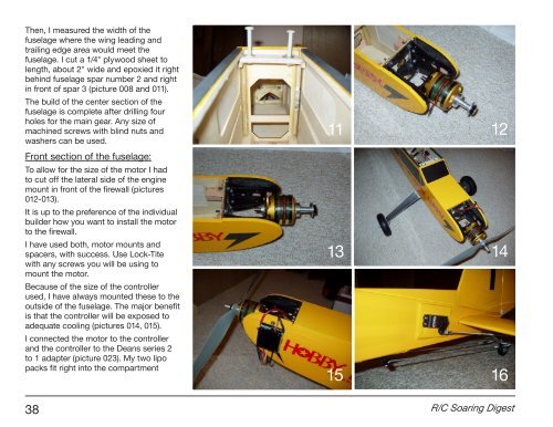
Front section of the fuselage:<br />
To allow for the size of the motor I had<br />
to cut off the lateral side of the engine<br />
mount in front of the firewall (pictures<br />
012-013).<br />
It is up to the preference of the individual<br />
builder how you want to install the motor<br />
to the firewall.<br />
I have used both, motor mounts and<br />
spacers, with success. Use Lock-Tite<br />
with any screws you will be using to<br />
mount the motor.<br />
Because of the size of the controller<br />
used, I have always mounted these to the<br />
outside of the fuselage. The major benefit<br />
is that the controller will be exposed to<br />
adequate cooling (pictures 014, 015).<br />
I connected the motor to the controller<br />
and the controller to the Deans series 2<br />
to 1 adapter (picture 023). My two lipo<br />
packs fit right into the <strong>com</strong>partment<br />
11 12<br />
13 14<br />
15 16<br />
38 R/C Soaring Digest