
Create successful ePaper yourself
Turn your PDF publications into a flip-book with our unique Google optimized e-Paper software.
<strong>Soaring</strong><strong>Digest</strong><br />
Radi C ntr lled<br />
November <strong>2012</strong> Vol. 29, No. <strong>11</strong>
CONTENTS<br />
November <strong>2012</strong><br />
Vol. 29, No. <strong>11</strong><br />
Front cover: James Mercado builds line tension prior to<br />
launching his Xplorer 4000. Photo taken at the <strong>2012</strong> World<br />
<strong>Soaring</strong> Masters, held at the AMA flying site in Muncie Indiana,<br />
by Mark Nankivil. Coverage of the event by Mike Reagan with<br />
more photos from Mark begins on page 63.<br />
Canon EOS Rebel T3i, ISO 100, 1/250 sec., f13.0, 36.0 mm<br />
3 <strong>RC</strong> <strong>Soaring</strong> <strong>Digest</strong> Editorial<br />
4 F5J Aircraft Design<br />
Marc Pujol details the initial concept and evolution of his<br />
Genoma 2 with text and numerous illustrations.<br />
40 Toba F3B/F3F from <strong>RC</strong><strong>RC</strong>M and Ole<strong>RC</strong>.com<br />
Reviewed by Andy Page.<br />
60 KST DS125MG servo<br />
Bill and Bunny Kuhlman review this metal gear, thin wing,<br />
digital servo from KST and Ole<strong>RC</strong>.com.<br />
World <strong>Soaring</strong> Masters <strong>2012</strong> 63<br />
Event coverage with text by Mike Reagan and photos by<br />
Mark Nankivil.<br />
Scenes from F3J Samba Cup <strong>2012</strong> 94<br />
A photo essay by Martin Pilny .<br />
Inexpensive Model Storage 108<br />
A reclaimed styrofoam box gets a new life.<br />
A Stuart Bradley creation.<br />
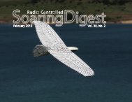
Back cover: An Enjoy3 passes in front of the partial moon.<br />
Photo taken by Martin Pilney at the F3J<br />
Samba Cup <strong>2012</strong>. More of Martin's photos from this event can<br />
be seen starting on page 94.<br />
Nikon D300, ISO 200, 1/1250 sec., f5.6, 200mm<br />
2 R/C <strong>Soaring</strong> <strong>Digest</strong>
R/C <strong>Soaring</strong> <strong>Digest</strong><br />
November <strong>2012</strong><br />
Volume 29 Number <strong>11</strong><br />
Managing Editors, Publishers<br />
Contact<br />
B 2 Kuhlman<br />
rcsdigest@centurytel.net<br />
http://www.rcsoaringdigest.com<br />
Yahoo! group: <strong>RC</strong><strong>Soaring</strong><strong>Digest</strong><br />
R/C <strong>Soaring</strong> <strong>Digest</strong> (<strong><strong>RC</strong>SD</strong>) is a reader-written monthly<br />
publication for the R/C sailplane enthusiast and has been<br />
published since January 1984. It is dedicated to sharing<br />
technical and educational information. All material contributed<br />
must be original and not infringe upon the copyrights of others.<br />
It is the policy of <strong><strong>RC</strong>SD</strong> to provide accurate information. Please<br />
let us know of any error that significantly affects the meaning<br />
of a story. Because we encourage new ideas, the content of<br />
each article is the opinion of the author and may not necessarily<br />
reflect those of <strong><strong>RC</strong>SD</strong>. We encourage anyone who wishes to<br />
obtain additional information to contact the author.<br />
———<br />
Copyright © <strong>2012</strong> R/C <strong>Soaring</strong> <strong>Digest</strong><br />
Published by B2Streamlines <br />
P.O. Box 975, Olalla WA 98359<br />
All rights reserved<br />
———<br />
<strong>RC</strong> <strong>Soaring</strong> <strong>Digest</strong> is published using Adobe InDesign CS6<br />
In the Air<br />
Another huge issue of <strong><strong>RC</strong>SD</strong>! <strong>11</strong>0 pages!<br />
Marc Pujol continues from where he left off in the October<br />
issue ("F5J Altitude," p. 10) with a complete examination of his<br />
Genoma 2 airframe, from initial concept through its evolution to an<br />
extremely well behaved contest entry.<br />
<strong><strong>RC</strong>SD</strong> was contacted by Ole<strong>RC</strong>.com earlier this year and given<br />
the opportunity to review the Toba F3B/F3F sailplane and the<br />
KST DS125MG servo. Fellow Seattle Area <strong>Soaring</strong> Society<br />
member Andy Page volunteered to review the Toba, while we<br />
handled the KST servo. Our sincere thanks to Ole<strong>RC</strong>.com for<br />
providing the review samples and particularly to Mei who handled<br />
a number of concerns quickly and professionally.<br />
Mark Nankivil was CD for the World <strong>Soaring</strong> Masters once again<br />
this year and he managed to forward nearly 2.5GB, more than<br />
350 images, to <strong><strong>RC</strong>SD</strong>. As you can imagine, going through this<br />
collection and choosing which to use was definitely a long-term<br />
project. MIke Reagan's write-up on the WSM event first appeared<br />
on the <strong>RC</strong>SE, and is reproduced here with his permission.<br />
Martin Pilny usually photographs F3B events, but he did attend<br />
the F3J Samba Cup <strong>2012</strong> near the village of Sebranice, Czech<br />
Republic, where Samba Models (home of the Pike series) is<br />
located. His photographs are filled with color and superbly portay<br />
the "flavor" of the event.<br />
And Stuart Bradley sent a few photos of his model storage unit, a<br />
reclaimed styrofoam box. We couldn't resist sharing it with <strong><strong>RC</strong>SD</strong><br />
readers.<br />
Thanks again to everyone who contributed to this issue!<br />
Time to build another sailplane!<br />
November <strong>2012</strong> 3
F5J<br />
AI<strong>RC</strong>RAFT<br />
DESIGN<br />
Initial concept and evolution of the Genoma 2<br />
Marc Pujol, marc.pujol1@free.fr<br />
How to structure a rational 3<br />
Regulation analysis 3<br />
The plane and its trigger elements 5<br />
Altitude gain in lift 7<br />
Thermal searching 12<br />
Return to the land field 13<br />
Landing 13<br />
Classification of trigger plane element 13<br />
After the Pasmespumas and the Genoma,<br />
here is my new F5J plane: The Genoma² 17<br />
The GENOMA² construction 21<br />
Tail and fin 21<br />
Wing 24<br />
Fuselage 27<br />
How does Genoma family is flying? 28<br />
The Genoma² in its first TD F5J contest 34<br />
Conclusion 36<br />
F5J discipline (also called ALES) appeared in January <strong>2012</strong>.<br />
This is the first time for electric glider categories where the<br />
propulsion set is not so important. This is a revolution. This<br />
is the end for all such very expensive gliders full of carbon<br />
technologies that allow them to be very light and highly<br />
resistant.<br />
So, for the first time, a standard glider can have “similar”<br />
chances against more optimized planes. Of course, similar<br />
doesn’t mean equal. There are still some differences between<br />
them. But strategies are of far more importance especially<br />
during a fly-off where the conditions are usually more<br />
demanding.<br />
This paper is written to provide you with a rationale that may<br />
conduct you into the selection of your next F5J plane. Of<br />
course, you can apply it to any other discipline with a little<br />
adaptation.<br />
4 R/C <strong>Soaring</strong> <strong>Digest</strong>
At the end, I will provide you with the<br />
result of my own rationale and deliver<br />
a full glider definition set - a glider that<br />
appears to be optimum and far cheaper<br />
than any commercial design set, a glider<br />
you can build either with foam and<br />
composite materials, epoxy and bagging<br />
or with structural techniques as I did.<br />
How to structure a rationale<br />
The rationale has three steps:<br />
• Regulation analysis and classification<br />
of points that appears important to win.<br />
• Identification of the trigger elements of<br />
a plane and their classification in relation<br />
to the regulation and air conditions.<br />
• Definition of the plane that meets such<br />
trigger classification.<br />
Regulation analysis<br />
The F5J regulation is quite simple:<br />
4 meter maximum for the wing span,<br />
electric propulsion, 30 seconds to climb<br />
up to 200m altitude, and a penalty of<br />
0.5 point per meter gained with the<br />
propulsion on.<br />
You have to perform a ten minute flight<br />
that includes the altitude gain with the<br />
motor and a precision landing (1m 10<br />
points).<br />
Figure 1: This is the ancestor (2008/2009) of the Genoma: The “Pamespumas,” an F3B<br />
plane from my friend P. Medard (PAtrick + MEdard + PUjol + MArc= Pasmespumas)<br />
that I have transformed to experiment with yawing stability. This was a first revolution<br />
for me. But not the last one!<br />
November <strong>2012</strong> 5
Of course there are additional<br />
requirements, but these are the majors.<br />
First of all, what appears important is<br />
the advantage to cut the motor at low<br />
altitude. If you switch it off at 100m<br />
and all the other flyers at 200m, that is<br />
a 50 point difference if you made the<br />
same flight length. (If all the competitors<br />
are making 10.00 minute flights and<br />
50 point landings, the first flyer gets<br />
1000 points and the second 550 / 600<br />
· 1000 = 917. That is 83 points less).<br />
In F3J, competitors are fighting for 5<br />
to 10 points... Imagine what 83 points<br />
per flight is... F5J is the first time where<br />
the objective is not to be at the highest<br />
altitude possible, nor to do it in the<br />
shortest time possible. We then have<br />
to think differently. I will say “opposite.”<br />
Instead of trying to launch high, we have<br />
to try to launch low. The plane must<br />
then have the ability to fly at low altitude,<br />
circling in the very small thermals you<br />
can encounter at such altitude.<br />
Instead of being in a hurry, let’s take<br />
time to go up and use the 30 seconds<br />
to reach the altitude and the location<br />
you think is good for thermaling. You<br />
can go 400m away (or even more) at the<br />
minimum altitude required to take the<br />
lift (for sure, you expect it is there). As<br />
a consequence, if you want to increase<br />
your chances, your plane must be quite<br />
big in order to be seen perfectly far away<br />
and must be very easy to fly.<br />
For sure, F5J gliders must be different<br />
from any other disciplines.<br />
This 30 second rule is the trigger<br />
rule of the discipline. It reinforces the<br />
strategy aspect and the pilot ability to<br />
successfully realize it.<br />
Exit powerful motors, hello light weight<br />
propulsion set.<br />
So let’s be very open in our mind and<br />
choices.<br />
This very first analysis reminds us that<br />
the flight has several phases and that<br />
each of them does not have the same<br />
influence on the final result. Determining<br />
which phase is important and which one<br />
is less or not important at all is a first<br />
mandatory step in the design of a new<br />
plane.<br />
I have then split the F5J TD flight into five<br />
phases.<br />
1. Altitude gain with propulsion<br />
2. Thermal search<br />
3. Altitude gain circling in thermal<br />
4. Return to the landing field<br />
5. Landing<br />
In order to classify them, I propose to<br />
you the following method:<br />
Compare each of them with the others<br />
and give 1, 2 or 3 points to the one that<br />
is more important. For example, Phase<br />
2 (thermal searching) is much more<br />
important than Phase 1 (altitude gain with<br />
propulsion). It takes a 3 rating.<br />
My personal rationale provides the<br />
tabular result shown in Table 1 at the top<br />
of the adjacent page.<br />
Of course, your understandings may lead<br />
to different notations. And this makes the<br />
diversity of our world.<br />
If we count points and crosses, that<br />
provides the results shown in Table 2 on<br />
the opposite page.<br />
It is difficult to trigger “Thermal search”<br />
and “Altitude gain in lift.” Both phases<br />
are quite equal. It is like chicken and egg.<br />
Which is first? It’s up to you to choose.<br />
My rationale is that the 30 seconds to<br />
climb is also a time to go into the lift (or<br />
close to it). So “thermal search” might be<br />
less important than “altitude gain in lift.”<br />
Of course you do not have to sacrifice a<br />
landing for an additional few seconds of<br />
flight. But the place of this phase means<br />
that you must find a thermal, take the lift,<br />
and go back first. Landing is in addition.<br />
6 R/C <strong>Soaring</strong> <strong>Digest</strong>
Table 1: The author’s personal rationale<br />
Is more important<br />
than<br />
Altitude gain with<br />
motor<br />
Altitude gain with<br />
motor<br />
Thermal search Altitude gain in lift Return to landing<br />
field<br />
Landing<br />
Thermal search X (3) X (1) X (1)<br />
Altitude gain in lift X (3) X (1) X (1) X (1)<br />
Return to landing<br />
field<br />
Landing X (3)<br />
X (3) X (1)<br />
Table 2: Results of evaluation of<br />
the author’s personal rationale<br />
Altitude gain in lift<br />
Thermal search<br />
Return to the landing field<br />
Landing<br />
Altitude gain with motor<br />
4 crosses<br />
6 points<br />
3 crosses<br />
5 points<br />
2 crosses<br />
4 points<br />
1 cross<br />
3 points<br />
0 crosses<br />
0 points<br />
Weight = 24<br />
Weight = 15<br />
Weight = 8<br />
Weight = 3<br />
Weight = 0<br />
November <strong>2012</strong> 7
So our plane must be able first to find and take a thermal.<br />
Second, it must have the ability to return home even far<br />
downwind, and then it must have the ability to land precisely.<br />
Each phase requires a specific ability that corresponds to a<br />
specific plane parameter. So let’s define the trigger elements of<br />
the plane.<br />
Of course a flight occurs in a specific air condition. This must<br />
be defined first:<br />
• Speed of wind<br />
• Density of thermals in the field. Are they numerous, fare away<br />
from the landing zone, upwind, downwind…<br />
• Thermal characteristics (force, size, catching altitude)<br />
• Turbulence of the air<br />
• Altitude of the field,<br />
• Humidity,<br />
• Ground and air temperature, sun<br />
• …<br />
In the design process, the plane will have to take into account<br />
all those elements.<br />
The plane and its trigger elements<br />
A plane is the result of alchemy. It is a complex balance<br />
between several parameters more or less independent, more or<br />
less against or in favors the others.<br />
That’s why it is important to have a clear view of their<br />
influences. (See Figure 2)<br />
We will define the plane thanks to physical parameters and<br />
aerodynamic parameters.<br />
Figure 2: Plane creation: A complex alchemy.<br />
Physical parameters are defined by:<br />
• Span<br />
• Chords and associated distribution<br />
• Wing surface<br />
• Aspect ratio<br />
• Fuselage length<br />
• Fuselage maximum front surface<br />
• Tail surface (if any)<br />
• Fin surface (if any)<br />
• Rudder, flap, aileron, elevator sizes<br />
8 R/C <strong>Soaring</strong> <strong>Digest</strong>
• Weight of all elements and associated location in space and<br />
inertia<br />
• Profile(s) data (Camber, thickness and position in chord of<br />
such…).<br />
• Tail volume<br />
• Center of gravity<br />
• …<br />
Aerodynamic characteristics are the consequences of such<br />
physical definitions on plane behavior:<br />
• Gliding ratio and speed associated<br />
• Minimum sinking rate and speed associated<br />
• Speed polar (Vz/Vx)<br />
• Yawing, rolling, pitching moment<br />
• Yawing, rolling pitching dynamic behavior (frequencies and<br />
damping factors)<br />
• …<br />
Some of such parameters are real parameters, others are the<br />
consequence of a conjunction of them and should be rejected.<br />
We then need to have a clear picture and analyze everything.<br />
So let’s look at the physical parameters that allow the accurate<br />
aerodynamic characteristic behaviors that comply with our<br />
classification and air conditions.<br />
In reality, we will do the reverse:<br />
For each flight phase, we have to determine and optimize the<br />
aerodynamic characteristic that fulfills our classification and<br />
find the associated physical characteristics that comply with it.<br />
Altitude gain in lift<br />
In order to optimize altitude gain in a thermal, we must first<br />
study the thermals - their size, location, altitude...<br />
Figure 3: A thermal can be modeled with few sinus functions.<br />
Realistic? Let say this is not so stupid. That’s a start of the<br />
understanding.<br />
In Western Europe, most of the thermals are quite narrow at low<br />
altitude. Let’s say that typically, the lifting air has a diameter of<br />
20m at 50m altitude. This will then be a reference for our plane<br />
design.<br />
Their location and density in the field depends upon the field<br />
itself - humidity, temperature difference, sun… Nothing to say<br />
for the plane except that in some cases you might require going<br />
far away to find them (so big plane, easy to fly). (See Figure 3)<br />
November <strong>2012</strong> 9
Knowing the thermals, then comes the<br />
strategy to circle and take the lift.<br />
There are roughly three strategies:<br />
(1) Make a circle, estimate the center of<br />
the lift and make the next circle around<br />
the estimated center…<br />
(2) Increase circling radius when the lift<br />
appears slow, relax the circling radius<br />
when the lift increases in intensity.<br />
(3) Cross the lift, make a quarter turn<br />
around the lift, cross it again, estimate<br />
the lift in size and center and then circle.<br />
Studies have been made for drones in<br />
order to optimize their flight duration.<br />
Different software has been tested to<br />
find the better strategy. To this end,<br />
this depends upon the turbulence<br />
rate. Strategy (1) may be a bit easier in<br />
turbulent air.<br />
But what about our planes? Nothing and<br />
lots of things.<br />
First of all, you need to circle and then<br />
have the ability to continue circling. But<br />
how tight?<br />
Knowing the size of the thermals and<br />
their intensities, we can compute the<br />
sinking rate of a plane circling and then<br />
predict if the plane is going up or down.<br />
This allows predicting the best bank<br />
angle to take the lift. This shows us that it<br />
Figure 4: The model of a lift is useful to estimate the optimum circling radius. For small<br />
lift, the bank is more or less at 45°. Quite tight isn’t it?<br />
10 R/C <strong>Soaring</strong> <strong>Digest</strong>
is required to circle at high angle (more or<br />
less 45° in our reference case). Our plane<br />
must then have the ability to circle with<br />
a small radius in a very easy way. (See<br />
Figure 4)<br />
Of course, in order to take low intensity<br />
thermals, the sinking rate of the plane<br />
must be minimum (advantage to big<br />
planes and light planes).<br />
Circling ability and minimum sinking rate,<br />
that’s two important aspects.<br />
The circling ability is, at first, a matter of:<br />
• Wing loading. It must be as reduced as<br />
possible<br />
• Cz. It must be as high as possible<br />
• Cz 3 /CX². This demands high lift and<br />
low drag. Some thin airfoils would<br />
potentially be required then.<br />
Despite what is usually believed, circling<br />
ability is not a matter of wing span.<br />
Make few calculations and you will see<br />
that if you can reduce the circling radius<br />
by a few percent, the climbing rate is<br />
increased much more. Circling ability is<br />
then the very important characteristic of<br />
the F5J category.<br />
To finally convince you, we had two<br />
competitions this year where the first<br />
or the second place was taken by a<br />
motorized F3K plane or an Easy Glider.<br />
Figure 5: The higher the aspect ratio, the higher the wing loading. It’s not for nothing<br />
that birds like eagles have quite low aspect ratio. And it is also not for nothing that sea<br />
gulls have a higher one. They do not fly the same air.<br />
November <strong>2012</strong> <strong>11</strong>
They where competing against full<br />
carbon 4m planes with good pilots...<br />
What were the differences between<br />
them: Ability in circling tight! This is also<br />
confirmed byfull size glider experiences<br />
where for example, a Pioneer (full metal<br />
very rustic plane, but very agile thanks<br />
to a long fuselage and which flies at low<br />
speed) was compared to a Bocian (SZD<br />
plane with a 30% better gliding ratio and<br />
speed). The first one was said as having<br />
better thermal ability without doubt.<br />
Of course, we need to fly in the wind.<br />
We then can define a wing loading range<br />
that will have to be obtained to cover that<br />
complete wind condition range. Let’s<br />
say that standard wing loading (for the<br />
complete plane) should be between 20<br />
and 30 g/dm².<br />
Since there is a direct link between<br />
aspect ratio and wing weight, the aspect<br />
ratio should be as high as possible<br />
to obtain the minimum wing load (i.e.<br />
the 20 g/dm²). It is then a matter of<br />
construction techniques and propulsion<br />
equipment weight and no more a matter<br />
of aerodynamics. (See Figure 5)<br />
If you have studied thermals, you must<br />
know that at low altitude they are quite<br />
small. Circling may then be most of the<br />
time at high angle of bank. This can be<br />
Figure 6: Blue and red curves are longitude and latitude. The plane is going straight.<br />
Light brown shows the altitude, the pink one is the speed and the green one is the<br />
yawing. As you see, even if the pilot tries to flight straight, the reality is a bit different.<br />
It is the conjunction of Dutch roll and phungoïde movement. All such movement<br />
(minimum V +/- 1m/s and yawing +/- 3 degrees) are very difficult to be seen without<br />
measurement devices.<br />
12 R/C <strong>Soaring</strong> <strong>Digest</strong>
feasible if, and only if, the yawing stability is optimum. In order<br />
to illustrate this, I will say that the plane must fly like an F3K<br />
one. As a consequence, the fuselage should be accurately<br />
long and the fin surface also accurately calculated. Here, it is a<br />
matter of dynamic behavior and no more a static one. Refer to<br />
<strong><strong>RC</strong>SD</strong> late 20<strong>11</strong> for a better understanding.<br />
I can say, without much pretention, that actual F3J planes<br />
are not optimum in that concern (except for the SUPRA in its<br />
original configuration (1.4kg)). The fuselage should be longer<br />
and fin surface increased.<br />
Once again, it is not sufficient to have a very good wing to<br />
make a good plane. If the plane doesn’t have accurate dynamic<br />
behavior, the wing can not express its best. And the pilot can<br />
not place the plane in a very easy manner at the right time in<br />
the right position at the right speed. (See Figure 6)<br />
Tight circling and long fuselage have consequences on fin flap<br />
size: When turning, the radius describes by the wing is not the<br />
same than the one on the fin. This means that the natural effect<br />
of a fin during circling is to go against the turn. In order to have<br />
a turn without skid, it is required to have the fin in the direction<br />
of the turn. And the longer the fuselage is, the more important<br />
the action on the fin is. Of course, in reality, due to bank angle,<br />
the action is on both fin and tail. But the rationale remains. (See<br />
Figure 7)<br />
As a consequence, for a long fuselage, the rudder should<br />
represent 50% of the chord or even more. 60% should be<br />
preferred.<br />
Circling requires also good low speed behavior. That means<br />
that the plane must have a speed range at low sink rate as large<br />
as possible. If you compare the Pike Perfect to the Supra, the<br />
Pike appears better in this area (and worse in others of course).<br />
Figure 7: When turning, the tail describes a trajectory with<br />
a radius equal to “R0” but at a distance equal to “A + R0”.<br />
For long fuselage “A” is not neglectable (up to 20 cm). As a<br />
consequence, the fin provides a torque in the opposite way of<br />
the turn. This requires fin action as if it was fully twisted from<br />
5° to 13°. For sure, the flap should be quite important for a 4m<br />
span glider.<br />
November <strong>2012</strong> 13
Figure 8: Trying to find the best speed that optimised up wind or downwind conditions, the McCready analysis shows us a range of<br />
speed between 6 to 15 m/s.<br />
This is fundamental. I made speed measurements and it is very<br />
difficult to fly at a fixed speed even with the speed information<br />
in my eyes (I have a Xerivision system for my experiments). Even<br />
in a straight line, the plane’s speed is varying from +/- 1m/s.<br />
This means that the minimum plane speed is much closer to the<br />
stall if the pilot expects to fly at Vzmin. If the plane speed range<br />
around Vzmin is not “very large,” it is absolutely impossible to<br />
fly at Vzmin. The plane has a good chance of stalling, especially<br />
during circling.<br />
And the more the flaps are deflected (in a positive way), the<br />
shorter this range is. So caution with flap during circling.<br />
As a consequence, the F5J plane will have profiles with a bit<br />
more camber than for F3J. Flaps should be used for transition<br />
or speed reduction (circling in the core of the lift if stable).<br />
14 R/C <strong>Soaring</strong> <strong>Digest</strong>
Thermal searching<br />
Despite the pilot ability to read the air and the ground, the plane<br />
must be able to reach the thermal prior to being too low in<br />
altitude.<br />
This means best gliding ratio and good ability to signal air<br />
movement (so reduced inertia for the whole plane).<br />
As the number of days without wind are quite reduced<br />
(especially in my living area), the plane must have the ability to<br />
have good gliding ratio between 7 to 15 m/s as it can be found<br />
playing with McCready approach taking into account sinking air<br />
and upwind flight.<br />
So profiles and aspect ratio should be optimized for such a kind<br />
of speed range.<br />
In F5J there is no requirement to have a plane that has good<br />
behavior at high speed. 100 km/h (28 m/s) or higher is only for<br />
fun. So keep it for F3J and other disciplines. (See Figure 8)<br />
Of course, in order to have good ability in circling and good<br />
gliding ratio in the wind, flaps are required for high wind<br />
conditions.<br />
The best possible gliding ratio is an alchemy that integrates<br />
profile drag at a defined lift, induced drag, Reynolds number,<br />
stability...<br />
As a consequence, the profile thickness should be optimized<br />
according to its camber, (this means try to reduce it in the<br />
respect of critical Re), and aspect ratio maximized. Both should<br />
integrate the weight prediction for a defined load resistance.<br />
For sure, the wing span is an important factor. 4 m span allows<br />
best gliding ratio. And since the wing span is limited, be sure<br />
that winglets will appear in the next generation of plane.<br />
As written, it is alchemy…<br />
Figure 9: Return to the landing field<br />
Return to the landing field<br />
Return to the land field is not only a matter of best gliding ratio.<br />
The question is should the plane capable to return flight after<br />
climbing in a thermal?<br />
After climbing, the plane should be far away downwind at a<br />
reached altitude. Should it come back safely? (See Figure 9)<br />
This is then a matter of climb angle (a mix of climbing rate and<br />
deviation to follow the thermal movement) and angle of descent<br />
upwind. The quicker the climb and the better the gliding ratio<br />
are, the higher is the chance to return home.<br />
The ability to take the lift gets once again its importance with all<br />
the consequences on plane definition.<br />
November <strong>2012</strong> 15
Landing<br />
Landing means reach the spot every<br />
times. Despite the pilot agility, the plane<br />
must have specific requirements:<br />
• Stop quickly when landing. In order<br />
not to destroy the propulsion unit, I<br />
would recommend not to land as F3J<br />
planes. Since it is not possible to affix<br />
any stop feature, the only remaining<br />
solution is a tail that continues under<br />
the fuselage like for the AVA / Bubble<br />
Dancer, F3K planes…<br />
• Have good maneuverability and good<br />
stability in order to pass through<br />
ground turbulence and reach the spot.<br />
Maneuverability and passing through<br />
turbulence without any affect are<br />
quite opposite. Since there are great<br />
advantages for all the other phases to<br />
have very low inertia, the plane should<br />
have very good maneuverability as<br />
compensation.<br />
Here, it is a matter of rolling rate, braking<br />
efficiency, descent angle at a fixed<br />
speed. Consequences are on inertia, flap<br />
and aileron sizing, inertia (construction<br />
issues are once again important…) and<br />
also high dihedral in order that wing tips<br />
do not touch the ground prior landing...<br />
Classification of trigger plane element<br />
Let’s take all of the plane parameters and<br />
estimate their consequences (in terms<br />
of advantage / disadvantage) for the five<br />
flight phases.<br />
Of course, for F5J, the first phase<br />
(reaching altitude) could be forgiven since<br />
it has no influence on the plane. But<br />
this is not the case for most of the other<br />
gliding categories.<br />
This provides the following table for the<br />
majors. But you can complete it by any<br />
parameters you want. (See Table 3)<br />
As you can see, there are three<br />
categories of parameters:<br />
• The very important ones. In this first<br />
category are found two dynamic<br />
stability parameters (on pitching<br />
axis) and only one static parameter<br />
(wing span). This means that despite<br />
what was usually admitted, the most<br />
important thing is to have a very stable<br />
and well balanced plane.<br />
• The important ones. Quite close to the<br />
first category in terms of importance,<br />
are found other dynamic parameters<br />
such as yawing, inertia. Then are<br />
coming what we can call the “standard<br />
plane parameters” (fuselage length,<br />
mass, profile curvature...). Once again<br />
we have to point out the very high<br />
importance of the dynamic behavior<br />
for a F5J plane. This is not the only<br />
category that may have similar<br />
classification. But very few planes are<br />
studied in this way. AVL and XFLR5<br />
are here to improve our design.<br />
• The others. It is quite surprising to see<br />
parameters like drag, gliding ratio,<br />
aspect ratio... at the bottom of the<br />
classification. Is it so surprising? Look<br />
at an eagle and look at a sea gull.<br />
Two birds, two types of flights, two<br />
adaptations to an environment. So<br />
don’t be so surprised.<br />
After the Pasmespumas and the<br />
Genoma, here is my new F5J plane:<br />
The Genoma²<br />
After a first trial with a modified F3B (with<br />
a very long fuselage for good yawing<br />
stability) which shows the interest of<br />
yawing stability calculation, I developed<br />
a series of profiles specifically for the<br />
F3J category. The idea was to promote<br />
speed (and then small airfoil curvature<br />
and very low thickness), high aspect<br />
ratio (to compensate the lower airfoil<br />
lift by reducing the induced drag and<br />
lift). The objective was to be better than<br />
the Supra in speed and transition. We<br />
constructed it in a few exemples. I put all<br />
16 R/C <strong>Soaring</strong> <strong>Digest</strong>
Table 3: Aircraft parameters and consequences for five flight phases<br />
November <strong>2012</strong> 17
of the information for the construction on<br />
a 200 illustrated pages (French language<br />
actually only, sorry). For those interested<br />
see the website for more details. We measured<br />
its performance and I have to confess<br />
that this is quite a satisfaction to obtain<br />
a plane that corresponds exactly to the<br />
calculation. I wanted it, I obtained it, and<br />
I love it. This plane is the best plane I<br />
have ever piloted. (I have constructed<br />
more than 100 planes.) (See Figure 10)<br />
Then came the F5J category and I<br />
restart from scratch my studies taking<br />
into account new considerations such<br />
as minimum weight for a defined aspect<br />
ratio and G load, minimum circling<br />
diameter...<br />
This conducts me to the GENOMA².<br />
It is similar to the Genoma, but quite<br />
different for some aspects:<br />
• Less aspect ratio to reach the 20g/dm²<br />
wing load,<br />
• higher camber for the profiles for lower<br />
minimum speed,<br />
• lower minimum wing load,<br />
• more span (4m) to be at the maximum<br />
of the F5J regulation,<br />
• a new series of profiles taking<br />
information from the Pike perfect, the<br />
Supra, the AVA...<br />
Figure 10: The GENOMA as defined in 2010. It flies like a F3K plane with a 3.65 m span.<br />
18 R/C <strong>Soaring</strong> <strong>Digest</strong>
Figure <strong>11</strong>: Comparison polars<br />
• a new fin and tail to adjust dynamic<br />
behavior.<br />
The objective was:<br />
• To improve speed range at low sink<br />
rate in order to avoid stall during<br />
circling. In this respect, the Pike<br />
perfect was taken as a reference.<br />
• To improve Gliding ratio between<br />
minimum sink and 15 m/s. The Supra<br />
is taken as the reference for this<br />
aspect.<br />
• To improve low speed.<br />
• To have the same or even better<br />
yawing and pitching stability than the<br />
Genoma.<br />
This provides me with the planform<br />
shown in Figure 12 (next page), with an<br />
associated profile series (icons and links<br />
on next page).<br />
The length of the fuselage is the same<br />
as for the Genoma for transportation<br />
reasons, 2.2m long, that’s for me nearly<br />
the maximum. Otherwise it is difficult<br />
to store it at home or in the car without<br />
risk of damage... And I don’t want yet to<br />
make a fuselage in two pieces.<br />
Dimensions are:<br />
• Fuselage from nose to leading edge:<br />
53 cm. Don’t think this is too much.<br />
When using a 105g / 700W geared<br />
November <strong>2012</strong> 19
Genoma 2 Airfoil Series<br />
Genoma F5J 1: <br />
Genoma F5J 2: <br />
Genoma F5J 3: <br />
Genoma F5J SAUMON: <br />
Figure 12: Genoma 2 (<strong>2012</strong>)<br />
20 R/C <strong>Soaring</strong> <strong>Digest</strong>
motor and a 1300mA/h 3S Li-Po<br />
battery (or even a 2200mA/h 3S Li-<br />
Po), this is not too much. This is just<br />
sufficient for the very long rear lever<br />
arm.<br />
• Fuselage from wing leading edge to<br />
the end (fin trailing edge): 166 cm<br />
• Max section dimension of the fuselage:<br />
6*4 cm<br />
• Wing area: 85.56 dm²<br />
• Root chord: 26 cm<br />
• Aspect ratio: 18.7.<br />
• Max diameter of the boom = 34mm. Of<br />
course you can reduce this diameter in<br />
order to be lighter. But caution with the<br />
fuselage flexibility...<br />
Wing data and profiles:<br />
• Root: Dihedral = 3° - Chord = 26cm -<br />
Thickness = 7.8% - Camber = 2.9%<br />
• Root + 50cm: Dihedral = 3° - Chord =<br />
25cm - Thickness = 7.5%; Camber = 2.7%<br />
• Root + 100cm: Dihedral = 7° - Chord =<br />
24cm - Thickness = 7.5%; Camber =<br />
2.7%.<br />
• Root + 169cm: Dihedral = 7° - Chord =<br />
16cm - Thickness = 7.3%; Camber = 2.6%<br />
• Root + 190cm: Dihedral = 7° - Chord =<br />
<strong>11</strong>0cm - Thickness = 6.8%; Camber =<br />
2.4%<br />
• Root + 200cm: Chord = 5cm - Thickness =<br />
6.8%; Camber = 2.4%<br />
Flaps are 30% of the chord from the<br />
root until 15 cm prior to the tip. Then<br />
the aileron is gradually reduced down to<br />
20%. Flap and aileron are “on the same<br />
line” looking at the plane from the top.<br />
Tail:<br />
• Surface = 6.8 dm² (8% of wing<br />
surface). But look at the comfortable<br />
tail volume.<br />
• Tail leading edge distance from wing<br />
leading edge = 1315 mm<br />
• Root chord = 12cm<br />
• Aspect ratio = 8.4<br />
• Tail volume = 0.47<br />
• Profile = HT-13<br />
Fin:<br />
• Surface = 7.4 dm²<br />
• Fin leading edge distance from wing<br />
leading edge = 1500 mm<br />
• Root chord = 18.5cm<br />
• Height = 55cm (including <strong>11</strong> cm under<br />
the boom)<br />
• Profile = HT-13<br />
• 50% of the surface makes the rudder.<br />
This is a minimum. You can go up<br />
to 60% without a problem but with<br />
benefits.<br />
The GENOMA² construction<br />
There are 20 moulds made for the<br />
Genoma. We planned initially 21, but<br />
finally limited the number... Quite a lot<br />
I know. That’s why the Genoma was<br />
started in a club. One guy is doing this,<br />
the other one that…<br />
We then succeed without much difficulty<br />
to create these moulds in less than 6<br />
months. And in one year of construction,<br />
the Genoma was flying. Of course, for<br />
the Genoma² I reuse all of the moulds,<br />
even if the profiles are a bit different.<br />
The D-box is quite flexible so there is no<br />
adaptation problem.<br />
For details, look at the 200 pages (in<br />
French, sorry, but with lots of photos)<br />
written at www.xerivision.com (this is not<br />
my website). (See Figure 13)<br />
Tail and fin<br />
The spar of the fin and the sub-fin is<br />
realized with a carbon rod 3*0.8 mm on<br />
upper and lower side. The spar caps are<br />
made with balsa. After it has been glued<br />
together (Cyano), a Kevlar fishing wire is<br />
rolled around. Then balsa profile leading<br />
and trailing pieces are glued. The trailing<br />
edge is made with a carbon rod 3*0.8<br />
mm and the trailing edge is covered<br />
with a small sheet of carbon (cut from a<br />
unidirectional 80g/m² carbon layer).<br />
The leading pieces are glued every 1.5cm<br />
and the trailing pieces can be glued<br />
every 4.5 cm. (See Figure 14)<br />
November <strong>2012</strong> 21
Figure 13: The Genoma² prior to recieving its composite D-boxes. This is quite long<br />
to proceed but not very difficult at all. Nothing requires many tools (We used a CNC<br />
machine for cutting the profiles, you can do without).<br />
Figure 14: Stabilizer (L) and vertical fin<br />
and rudder (R) drawings.<br />
22 R/C <strong>Soaring</strong> <strong>Digest</strong>
Figure 15a and 15b: How to mould the D-boxes? Easy. On a<br />
positive mould. Not much science behind this. For the wing,<br />
two layers of Kevlar of 60g/dm² is fairly sufficient (the wing can<br />
support all aerobatic maneuvers). For tails and fin, a 60g/dm²<br />
kevlar is OK.<br />
The D-Box is made with a sheet of Kevlar (60g/dm²).<br />
Do not forget the D-box for the rudder. It has a very important<br />
role. 1.5cm large is sufficient.<br />
The secret of the D-Box is in the glue to assemble it. There<br />
is always too much glue! If you count at the end, this glue<br />
represents up to 25% of the total weight. Far too much for a so<br />
little resistance. Try to reach 10 to 15% and you will be a king.<br />
(See Figures 16 and 17a and 17b)<br />
Wing<br />
The wing is a tail that is a bit bigger. That’s all… But the<br />
techniques used are identical. (See Figures 18 and 19)<br />
The spar is made with two layers of carbon sheet 15*1mm at<br />
the root. Then after 500mm, only one layer remains. The spar<br />
is also tapered down to 2mm at the tip.<br />
Leading profile pieces are glued (Cyano) every 2cm and the<br />
trailing edges every 4cm.<br />
November <strong>2012</strong> 23
Figure 16: Tail and fin. Making them lighter and stronger is<br />
difficult but possible. There are too many wood sticks in the fin.<br />
We can suppress 2/3 of them for the rudder. But this was for<br />
the look!<br />
Figure 17a: Vertical<br />
fin and rudder and<br />
horizontal stabilizer<br />
mounted to fuselage<br />
before covering.<br />
Figure 17b: Vertical fin<br />
and rudder and horizontal<br />
stabilizer mounted<br />
to fuselage after<br />
covering.<br />
24 R/C <strong>Soaring</strong> <strong>Digest</strong>
Figure 18: Wing plan<br />
November <strong>2012</strong> 25
Figure 19: All balsa wood pieces have been realized on a CNC<br />
machine. Of course, on request, files can be provided.<br />
Figure 20: How to mould the flap and aileron D-boxes — on a<br />
window! Do not forget to “wax” it.<br />
26 R/C <strong>Soaring</strong> <strong>Digest</strong>
Above, Figure 21: Few detail of the wing to fuselage assembly<br />
system.<br />
Upper right, Figure 22: General view of the wing. The leading<br />
edge is covered with paper for protection reason. It will be replaced<br />
by molded D-box.<br />
Lower right, Figure 23: View of D-box mold under process. On<br />
top, you can see the D-box bagged, in the center the D-box<br />
results and in the bottom of the picture the D-box mold.<br />
November <strong>2012</strong> 27
Figure 24: A view of the fuselage to better appreciate the design.<br />
Figure 25: The details on how to fix the tail. Very<br />
similar as the Supra / Bubble Dancer... Except that<br />
here, everything is inside the boom. Everything is<br />
made with very rustic moulds (and easy to be made).<br />
Nothing difficult!<br />
The leading edge D-box is made with<br />
2*60g/dm² Kevlar layers. This is enough<br />
for F5J. The standard 165 g/dm² Kevlarcarbon<br />
layer is too much / too heavy for<br />
this category.<br />
The flap and aileron D-boxes are cut<br />
from a 60g/dm² Kevlar layer that was<br />
moulded on a window… (See Figure 20)<br />
Nothing difficult. Everybody can do it<br />
with a bit of experience or in a club. It is<br />
only a bit long. (The wing requires more<br />
or less 30 hours of work if you have the<br />
D-box moulds and the wing ribs already<br />
programmed for the CNC milling!)<br />
But the result is... Magic! (See Figures 21,<br />
22 and 23)<br />
Fuselage<br />
The Genoma² fuselage is the same as the<br />
Genoma.<br />
Total length: 2.2m<br />
Nose to Leading edge distance =<br />
530mm. This is not too much. I strongly<br />
recommend not to shorten the nose.<br />
Other dimension: Maximum larger =<br />
40mm, Maximum high = 60mm. Enough<br />
place to fix everything you want in terms<br />
of propulsion, batteries, servos... The<br />
fuselage section is neither round nor<br />
rectangular. We prefer an ovoid section<br />
as you can see in the pictures.<br />
Wing incidence is 4°, so that the plane<br />
flies with a horizontal boom.<br />
This is the flying attitude the Genoma<br />
family has. And the fuselage of course<br />
28 R/C <strong>Soaring</strong> <strong>Digest</strong>
emains in this position with flap put<br />
down or up.<br />
This horizontal attitude is for me quite<br />
important to manage flight when the<br />
plane is very far away.<br />
Note: I usually play with the plane flying<br />
600m away (in our field this is where<br />
thermals are).<br />
I confess that most of the F3x planes<br />
do not have such incidence. But their<br />
designs are based on speed. Remember,<br />
F5J is not F3J.<br />
The boom is horizontal and the nose has<br />
a 2.5° pitch starting at the wing leading<br />
edge. (See Figure 24 and 25)<br />
How does Genoma family fly?<br />
The Genoma (First) is quite magic. You<br />
play with it like with a F3K plane.<br />
Of course because of the wing span, it<br />
is a bit different. The rolling rate is lower,<br />
the gliding ratio is far better, but you do<br />
what you want when you want in a very<br />
small volume. I’m not a great pilot even<br />
after I playing with gliders for 40 years,<br />
but I still started to circle at 20 m altitude<br />
during the second flight.<br />
The next thing to be noticed is that it is<br />
very easy to fly. For the last two years it<br />
is the plane I use for teaching new pilots.<br />
The trainees also learn how to land with<br />
Figure 26: One of my trainees with the Genoma after his flying lesson. They learn<br />
everything with it.<br />
it. I use an “Easy Glider” at the very<br />
end of my teaching lessons in order for<br />
trainees to know how to play with their<br />
own future plane! (See Figure 26)<br />
Easy to fly means also easy to circle at<br />
low altitude. As an example, I circle 10<br />
minutes between 20 and 50 m altitude<br />
as if it was a normal flight. Thermal lift<br />
was ridiculous, small, but of course<br />
quite frequent. And this flight was made<br />
without any difficulties. I didn’t feel<br />
uncomfortable at all during the flight<br />
nor exhausted after the flight even if the<br />
plane was 100 to 200m away from the<br />
landing zone. (See Figure 27)<br />
One of my favorite ways to fly in a<br />
thermal is to play with the “hand brake”<br />
when turning (like with the car): When<br />
circling in the downwind branch, the<br />
rudder is put at its maximum. The<br />
November <strong>2012</strong> 29
Figure 27: The proof that the Genoma can fly at very low altitude. And “No fear, no<br />
fun” is not my motto.<br />
ailerons are in the opposite direction so<br />
as to maintain a flat attitude. The plane<br />
is turning on its wing root, like a car with<br />
the hand brake. A bit of pitch when being<br />
upwind, then aileron order to restart the<br />
turn...<br />
When done in the very core of the lift,<br />
the plane has a “vertical” trajectory...<br />
Interesting, no?<br />
Another refinement I’m using now is the<br />
fourth axe management. I play with the<br />
camber of the wing all along the flight.<br />
Instead of using pitching throttle (left<br />
stick), I prefer to use the camber one<br />
placed on the right stick. The speed<br />
variation is as with the left stick but the<br />
plane fuselage remains horizontal. This<br />
is marvelous during circling. You “push”<br />
when you are going upwind, and pull<br />
when going downwind. The pitching axis<br />
is used to maintain the circling radius<br />
and the camber one manage the flight<br />
speed. The plane then circles in a very<br />
smooth and regular circle without having<br />
much pitching order to be provided.<br />
And the fuselage remains in the same<br />
position (horizontal) which is once again<br />
fundamental to better feel the thermal.<br />
If you had used the pitch, the fuselage<br />
attitude would have changed due to your<br />
pitching action… (See Figure 28)<br />
30 R/C <strong>Soaring</strong> <strong>Digest</strong>
Figure 28: The Genoma in flight. The fuselage doesn’t appear so long does it?<br />
November <strong>2012</strong> 31
In terms of yawing behavior, measures<br />
and computation are very close. Again,<br />
“Magic”! (See Figure 29)<br />
What about Genoma² flight<br />
The new Genoma² is as expected from<br />
calculation.<br />
It flies as its older brother:<br />
• It is a F3K plane but with 4m span.<br />
This means that the way to fly it similar to<br />
any F3K plane with of course more inertia<br />
(more time to roll).<br />
• It has this ability to circle very shortly.<br />
And in this respect this open new way<br />
of flying; On top of the standard “gentle<br />
circling” way of flying with very smooth<br />
actions on the sticks that you need to<br />
master for TD flight, the Genoma family<br />
allows to have a more aggressive way<br />
of flying without much difficulty. This<br />
is quite useful at low altitude when the<br />
thermals are narrow and not very regular.<br />
Here, the yawing stability behavior is a<br />
real advantage compare to any other<br />
planes.<br />
• It is a full aerobatic plane. Loop, roll,<br />
invert flight, chandelle are easy. The first<br />
ones (1 loop + 1 roll + 1 chandelle) were<br />
made starting at less than 50m altitude…<br />
and of course finished by a landing close<br />
to the pilot.<br />
Figure 29: Comparison of different planes in yawing. The Genoma (in light blue) is far<br />
better than any other planes (Supra original in yellow, Pike Perfect in purple, F3B plane<br />
in dark blue) which provides it with very good circling ability. The Genoma² is of course<br />
as its older brother.<br />
32 R/C <strong>Soaring</strong> <strong>Digest</strong>
Figure 30: First flight of the Genoma (First version) was in January 2010. Since that time, this 1.9kg plane flies every week without<br />
trouble. It even succeeds to flying three minutes alone (without any control due to an electrical problem) and crash in a field after a<br />
50m dive without any destruction. So light and so resistant!<br />
November <strong>2012</strong> 33
Figure 31: The man is 1.93m long. Quite a plane, no? The Genoma² weighs 1.6-1.7kg.<br />
It is 300g lighter than the Genoma for greater span and surface... The Genoma² is also<br />
able to make the barrel rollss in circles or any other aerobatic maneuver.<br />
• Stalling is difficult with a radio mix<br />
“Elevator” -> “Camber.” In such condition<br />
the stall is a 5m loss of altitude with<br />
recovery after. And if you insist, it starts<br />
for another cycle of stall/lost of altitude/<br />
recover. Then the only way to escape is<br />
to use the butterfly airbrakes.<br />
On top of this abilities are:<br />
• The potential wing load range of 19<br />
to 35g/dm² which is optimum to any<br />
flight condition. As a consequence, the<br />
circling radius (minimum 6m compared<br />
to the 10m for the Genoma) and the<br />
minimum speed and sinking rate are<br />
improved.<br />
• The sub-fin acts as a stopper during<br />
landing. The grass “sliding” is only<br />
50cm. That’s better than the 2m to<br />
3m for the first version. I wondered<br />
whether the fuselage and sub-fin<br />
attachment will be strong enough.<br />
For “standard” and “nearly standard”<br />
landing (that’s what I made actually),<br />
nothing adverse happens.<br />
As already expressed, it is very difficult<br />
to measure minimum sinking rate or best<br />
gliding ratio. It depends so much on air<br />
conditions that you can say one thing<br />
and it’s contrary. I then will not provide<br />
values that don’t mean anything. Just to<br />
say that with 30km/h wind, the Genoma²<br />
34 R/C <strong>Soaring</strong> <strong>Digest</strong>
without ballast stays in the sky with a<br />
“standard” sinking rate (as for any other<br />
planes for such wind that obliges to<br />
fly at best gliding ratio and not at best<br />
sinking rate). Of course, with such wind,<br />
it is recommended to have 500g to 800g<br />
ballast for better penetration / gliding<br />
ratio. In this case Genoma and Genoma²<br />
are quite equivalent. Differences could<br />
not be measured for me.<br />
The Genoma² in its first TD F5J contest<br />
After only two flights in 30 to 40 km/h<br />
wind, I made an F5J contest. The plane<br />
had never been ballasted, circling had<br />
not been tested, flap compensation<br />
was not well triggered, airbrakes and<br />
precision landing never tested.<br />
Because F5J is a new discipline, only few<br />
contests occur in my area. I had then to<br />
participate.<br />
I also have to state that I’ve only made<br />
competitions two times in my life. The<br />
first one was in 1980 (I finished last) and<br />
the second in 1982 (I finished third but<br />
we were only three competitors and I<br />
crashed my plane on the first flight). So,<br />
in reality I consider that it was my real<br />
first Thermal Duration (TD) contest.<br />
Because of the pressure and the very<br />
few number of flights with the Genoma²<br />
I wanted to start with the Genoma. But<br />
Figure 32: The Genoma² (facing the camera) and the Genoma ready for flight.<br />
November <strong>2012</strong> 35
then the first failure occurs during a<br />
flight test: a flap servo failed. Thanks<br />
Mister Murphy! I then have to fly with the<br />
Genoma² which you will recall had only<br />
two flights since new... Not a good way<br />
to start a TD contest.<br />
Other competitors had made<br />
competitions for years (F3J, other<br />
TD types...). Gliders used were Pike<br />
Perfect, Maxa, AVA, Shadow, Electra,<br />
Graphit, Alfa club and homemade planes<br />
including the Genoma².<br />
Conditions were good with low wind<br />
(10 to 25km/h wind) which obliged the<br />
lightest planes (Maxa and Genoma²)<br />
to ballast a bit when the wind went up<br />
(+ 250g). The AVA didn’t have ballast<br />
capability which was a disadvantage in<br />
some flights. All other planes had wing<br />
loadings between 27 and 35g/dm² and<br />
didn’t require ballasting.<br />
I was then quite impressed and anxious<br />
for the first run.<br />
I then flew and discovered that the plane<br />
is very good, and even without thermals,<br />
did equal with the others. My first landing<br />
was not so good because I didn’t know<br />
how the plane reacted or how to land on<br />
a spot...<br />
Then all the other seven flights proved to<br />
me the following:<br />
Figure 33: Genoma² for its first flight. Except few adjustments, it flies perfectly<br />
and I found immediately comfortable. It is even better in circling ability due to the<br />
possible low wing load (19g/dm² without ballast). Of course things needs adjustment<br />
(compensation, trim…).<br />
36 R/C <strong>Soaring</strong> <strong>Digest</strong>
1) The Genoma is better than any others<br />
in circling. It flies like an F3K plane and<br />
of course can also fly like an F3J plane.<br />
This ability to circle in an aggressive way<br />
in a very low volume is a real and major<br />
advantage for a TD competition. And<br />
then, my analysis in this respect is really<br />
valid. With thermals, the plane always<br />
went over the others or at the same<br />
altitude. The Genoma² opens a new flight<br />
envelope compared to existing 3m to 4m<br />
span gliders. And I’m not an expert in<br />
thermal hunting!!!<br />
2) Transition: The plane is as good as<br />
the others. I didn’t play much with flap<br />
during transition because of the flap<br />
compensation adjustment was not<br />
correct. But I’ve never been trapped<br />
downwind as the AVAs were. What I<br />
can say is that the higher camber of<br />
the Genoma² wing indicates you need<br />
to play with the flaps if you want to be<br />
as good as a Maxa for example. And<br />
of course, a full moulded wing made in<br />
accurate moulds are always better than<br />
a handmade one. But once again, the<br />
costs are very different and for the price,<br />
the Genoma² is really good.<br />
3) I discovered how to land after the TD<br />
contest when I offered other competitors<br />
to fly the Genoma². It is finally very<br />
simple. Plane has to transit back to the<br />
spot in order that it reaches a 2m altitude<br />
5m in front of the spot. Then full brake.<br />
The plane stops in the air, pitches and<br />
falls like a parachute at low and constant<br />
speed. It remains agile on all axes and<br />
you can adjust the spot. At the very end,<br />
pull on the elevator stick and the plane<br />
lands flat. The under fin and the low<br />
speed immediately stop the plane. As the<br />
English say “it’s a piece of cake” if you<br />
have a few practice sessions.<br />
4) Concerning the sinking rate, it is as<br />
good as any others. With real moulded<br />
wing it will be a must for sure!<br />
So my landing was not good at all. Two<br />
outside, one at 1.2m, the others between<br />
3 meters and 5 meters.<br />
I knew I obtained 1000 points for one<br />
run. I miss another one for a stupid<br />
misunderstanding with my caller (I<br />
thought that only two minutes remained<br />
and exited the thermal — I was 100m<br />
over all the others — and start my<br />
approach back... When I reach 180m<br />
altitude (50 m lower than others), I<br />
discover that 5 minutes of the flight<br />
remains... And no more thermals except<br />
very narrow ones... So I get an 8 min 40<br />
second flight.<br />
And finally, I finish the contest in third<br />
position... Good for a start isn’t it?<br />
So despite the inability of the pilot to<br />
manage the sticks correctly, the plane<br />
has real potential.<br />
Conclusion<br />
Yawing stability is fundamental for our<br />
planes. This was not calculated in the<br />
past due to lack of knowledge and tools.<br />
But thanks to M. Drela and A. Deperrois,<br />
this is no more the case. This could be<br />
applied to all our disciplines. Aerobatic<br />
planes and F3K already do it. For those<br />
who play other games, you can also<br />
apply the yawing stability calculation<br />
principles. As an example, I made a<br />
racing plane with good results. (See<br />
Figure 34)<br />
Making our own model is still possible for<br />
F5J planes. It’s not a matter of expertise<br />
but only a matter of time to construct it.<br />
This means that this discipline has room<br />
for experimentation and that you are not<br />
obliged to spend $1000 to $2000 to get a<br />
single plane.<br />
The cost of the Genoma is about $400<br />
without equipment. And if you make it<br />
in a club, this cost of course could go<br />
down.<br />
Yes, this is quite more expensive than<br />
making an F3K plane, and then we need<br />
to make calculations to predict the result<br />
prior to launching the building phase. But<br />
November <strong>2012</strong> 37
Figure 34: A small racer (1m span, 300w only) where the fuselage length is longer<br />
than the span. Despite the fact that this configuration disturbs our minds, it is not so<br />
unusual for real racing planes. The fuselage increase allows us to reduce fin and tail<br />
dimensions (and then drag) and to increase the stability. Flight is like an arrow —”on a<br />
rail.”<br />
the flying envelop of a 4m span plane is<br />
also far more extended!<br />
The Genoma² has been created<br />
taking into account 40 years of gliding<br />
calculation experiences, 100 planes<br />
constructed (most of them were<br />
homemade) with about 25 years for<br />
electric TD planes including some for<br />
duration records. The Genoma family<br />
has already made one to one TD flights<br />
with good results. The first competition<br />
result is also quite encouraging. You<br />
may say that this could come from the<br />
pilot itself. But my experiences (and<br />
especially my first competition) show me<br />
that it is mainly due to the plane itself,<br />
and especially to the yawing stability. Of<br />
course this doesn’t mean that it is the<br />
best plane.<br />
If you are satisfied with a defined wing<br />
(even I think that the Genoma² is more<br />
accurate for F5J, I will never say that<br />
actual F3J wings are not good for F5J<br />
category), you can then improve your<br />
plane by redesigning a fuselage and a fin<br />
and rudder for accurate yawing stability<br />
behavior. This is then far cheaper than<br />
creating a new plane. And tools like<br />
AVL or XFLR5 are here to guide us. This<br />
will force the builder to propose real<br />
good planes and not planes that have<br />
38 R/C <strong>Soaring</strong> <strong>Digest</strong>
In a future issue of <strong>RC</strong> <strong>Soaring</strong> <strong>Digest</strong>...<br />
commercial interests and fashion behind<br />
them.<br />
For those who want to have an up to date<br />
F5J plane, the Genoma² is the one you<br />
expected. You can then either:<br />
• Copy the Genoma² with the same or<br />
similar standard construction (wood<br />
and D-box),<br />
• Or use the Supra published building<br />
techniques and construct your<br />
Genoma²; this will of course work<br />
perfectly,<br />
• Or make some moulds with a CNC<br />
machine.<br />
If you make moulds (be sure that it is<br />
really feasible for a non professional guy<br />
to have a plane as light as the published<br />
version), I of course encourage you to do<br />
so. Only advise me in order to see how<br />
I can get one of those wings. Thanks in<br />
advance.<br />
We have seen that wing loading is very<br />
linked to aspect ratio. This means that<br />
if you do not want to have a plane at<br />
20g/dm² without ballast but something<br />
more closed to 25 to 30 g/dm². You can<br />
play with this parameter. One possible<br />
solution is then the Genoma first<br />
generation.<br />
So let’s fly F5J!<br />
Walk-around: Tony Condon’s Niedrauer NG-1<br />
Jerome Niedrauer built this glider in the early 1970s with the goal of reducing<br />
drag and increasing the performance of a stock BG-12. It is now owned by Tony<br />
Condon who says, “The NG-1 is the latest addition to the Condon family glider<br />
fleet and is an interesting collection of Briegleb BG-12 and custom made glider<br />
parts. Most people can’t figureout what it is at first glance, and the best short<br />
answer I have heard to describe it is simply “Experimental.”<br />
November <strong>2012</strong> 39
Review<br />
from <strong>RC</strong><strong>RC</strong>M and Ole<strong>RC</strong>.com<br />
Andy Page, <br />
40 R/C <strong>Soaring</strong> <strong>Digest</strong>
From designer/pilot Carlos Pisarello of<br />
Argentina comes the Toba, a new model<br />
for F3B multi task soaring, F3F slope<br />
racing, and electric assist soaring. Built<br />
by <strong>RC</strong><strong>RC</strong>M in China, the Toba is an<br />
affordable sailplane. But make no mistake,<br />
it is also a well built model and that makes<br />
it a great value. Tobas were flown by the<br />
Chinese team at the 20<strong>11</strong> F3B World<br />
Championships in China. Wing layup<br />
options are carbon D-tube and full carbon.<br />
The review model, supplied by Ole<strong>RC</strong><br />
in Hong Kong, is<br />
the full carbon version.<br />
What you get<br />
In addition to the airframe, <strong>RC</strong><strong>RC</strong>M supply<br />
machined plywood servo frames for flap<br />
and aileron servos, servo covers, flap horn<br />
fairings, a ballast tube (for F3F fuselage<br />
only), a servo tray, wire harness with<br />
Multiplex-style 6-pin connectors, carbon<br />
tube pushrods, clevises, wing pushrods,<br />
and a towhook.<br />
The frames are sized for MKS DS6125<br />
servos but with small modifications can<br />
be made to work with any thin wing servo.<br />
This is a nice accessory not often included<br />
and the use of wood makes them easily<br />
modifiable for versatility.<br />
Oddly, the towhook comes unassembled<br />
and with quite a loose fit of the unthreaded<br />
steel hook in the aluminum plate. I<br />
substituted one of the readily available<br />
units from Kennedy Composites.<br />
Specifications and Weights<br />
From the manufacturer’s website:<br />
Wing span: 3085mm<br />
Length: 1456mm<br />
Wing airfoil: <strong>RC</strong><strong>RC</strong>M2010-8<br />
Wing area: 58dm2<br />
Tail airfoil: <strong>RC</strong><strong>RC</strong>M2010-10<br />
Flying weight: 2000-2100g<br />
Review model component weights in grams:<br />
Left Wing: 747<br />
RIght Wing: 745<br />
Left Tail: 50<br />
Right Tail: 50<br />
F3B Fuselage with nose and tail cones: 208<br />
F3F Fuselage with nose and tail cones: 215<br />
Wing Joiner: 104<br />
Ballast Tube: 25<br />
Servo Tray: 14<br />
Wire Harness: 79<br />
Servo Frames (4): 16<br />
Servo Covers / Pushrod Fairings (6 pcs): 9<br />
Tail Joiners (2): 6<br />
Carbon Tube Pushrods (2): 31 (when cut to required length)<br />
The total F3B airframe weight without hardware or radio gear<br />
comes to 1910 grams, or about 67 ounces.<br />
For those of you who wonder about such things as weight<br />
distribution, the wing panel CG (finished with servos, covers, and<br />
wiring) is at about 40% of the half span.<br />
November <strong>2012</strong> 41
First impressions<br />
Like anyone else, I could not resist<br />
putting the parts together for the first<br />
time immediately after unpacking and<br />
was pleased to note that both the design<br />
and execution of this sailplane are well<br />
done. All of the joiners fit precisely right<br />
out of the box - a good sign.<br />
While these are purpose built tools for<br />
serious competition, it isn’t all about<br />
mechanics and performance. We like<br />
good looking airplanes too and the<br />
Toba does not disappoint with its very<br />
attractive lines. All the molding is very<br />
crisp and smooth. The graphics and<br />
colors are striking and not just the same<br />
old thing.<br />
Breaking it down again I moved on to a<br />
closer inspection. The molding quality<br />
is very good with clean and smooth<br />
edges. There is some visible telegraphing<br />
of fabric weave and spar edges on the<br />
wing panels but nothing unusual or<br />
concerning.<br />
The elevators and ailerons stop short of<br />
the tips, leaving a small vulnerable area<br />
that could be easily damaged. In fact<br />
one of the tail tips was slightly cracked<br />
already. A drop of thin CA fixed that. Care<br />
during transportation and handling will<br />
be needed to keep these intact.<br />
Available space for aileron servos is tight.<br />
This is a thin wing, measured at 8% at<br />
the root. If using the supplied covers,<br />
Complete<br />
contents laid out<br />
for inspection.<br />
Right out of the<br />
box. What a great<br />
looking sailplane!<br />
42 R/C <strong>Soaring</strong> <strong>Digest</strong>
Above: Flap wiper and pushrod fairing recess.<br />
Above right: Top hinged aileron wiper. Lower skin<br />
recessed for servo cover with integrated pushrod fairing.<br />
Right: One of the smoothest molded leading edges I’ve<br />
seen. No ridges, no pits.<br />
Below: Wing root. Middle pocket is for ballast.<br />
November <strong>2012</strong> 43
Supplied flap and aileron horns. Two of these escaped during<br />
shipping. Probably would work just fine, but I elected to make<br />
the replacements a bit larger for more substantial attachment.<br />
Final parts ready for installation.<br />
any of the typical aileron servos will fit.<br />
But if you wish to substitute flat covers<br />
you have very little space to work with.<br />
The inside height of the bay is about<br />
15/32" at the forward edge and only<br />
5/16" at the aft edge. Space is of course<br />
more generous in the flap servo bay,<br />
with 13/32" of height at the aft edge.<br />
Airtronics 94761’s fit nicely there.<br />
Unlike most composite sailplanes these<br />
days the ailerons are top hinged and<br />
intended to be driven with an external<br />
linkage. It may be possible to run the<br />
linkage inside but I used the stock setup<br />
and covers. Flaps are bottom hinged.<br />
The wipers are some of the best I’ve<br />
seen with very tight tolerances to the skin<br />
with no interference. Hinge movement is<br />
very good with plenty of range of motion<br />
and no binding at all.<br />
Two fuselages were supplied with the<br />
review package, for F3B and F3F. The<br />
F3B fuselage is very small in cross<br />
section and sets the wing at a positive<br />
angle of incidence. The F3F fuselage<br />
appears to have zero-zero incidence<br />
settings and is sized about 1/10" taller<br />
and wider in order to accommodate<br />
the ballast tube. Only one servo tray<br />
and harness were supplied. We did not<br />
build out the F3F fuselage as of the time<br />
of publication, though other than the<br />
differences noted above it is identical.<br />
The large cross section carbon wing<br />
joiner is typical for a two piece wing. It’s<br />
hollow, with two spaces on each end<br />
that can be used for ballast. It may not<br />
have much practical effect but the depth<br />
of the cavities on the subject joiner vary<br />
by about an inch left to right. Additional<br />
ballast cavities are molded into the wing<br />
roots. It should be possible to tailor the<br />
ballast to load it up without changing the<br />
CG. By my rough calculation there is a<br />
little less than 9 cubic inches of volume<br />
total in all cavities which would give a<br />
maximum possible capacity of about 43<br />
ounces of brass or 59 ounces of lead.<br />
Tailoring for CG will likely reduce the<br />
maximum possible weight.<br />
The wing skins are not pre-cut for flap<br />
pushrod exits or for horn installation.<br />
Supplied horns are glass and seem<br />
rather small for secure attachment.<br />
Two of them were lost in shipment,<br />
however, so I had no choice but to<br />
fabricate new ones. The hardware was<br />
packaged in thin, fragile plastic bags<br />
which had broken open, and the box was<br />
constructed so that small parts could<br />
44 R/C <strong>Soaring</strong> <strong>Digest</strong>
easily escape. Those lost horns might<br />
be doing endless speed runs across the<br />
Pacific in the belly of a 747.<br />
The removable nosecone is glass but<br />
there are four strips of approximately 1/4"<br />
wide carbon running through the nose of<br />
the fuselage itself. About 4" forward of<br />
the aft end of the nosecone the fuselage<br />
transitions to all carbon. The nose is<br />
open on the bottom rather than the top,<br />
keeping the pushrods clear of the wing<br />
joiner and your antennae on the best side<br />
of the mass of tightly packed radio gear.<br />
The Build<br />
First the flap pushrod exit was created<br />
by using a straight Dremel bit to cut the<br />
upper skin. The skin is molded with a<br />
recess for the pushrod fairing so there<br />
is no guesswork here, just cut it back<br />
leaving a small ledge for the fairing.<br />
Next, deflect the flap all the way down<br />
and relieve the auxiliary/shear spar using<br />
a small Dremel sanding drum. The same<br />
drum works nicely for relieving the flap<br />
wiper.<br />
Since I wanted to make the flap horn a<br />
bit longer than stock for the strongest<br />
possible connection, I opted to first test<br />
fit a pattern cut from 1/64" ply before<br />
cutting the circuit board stock.<br />
First I cut a squarish opening in the flap<br />
shear web using a #<strong>11</strong> blade. A couple of<br />
eyeballed trials using scissors to cut the<br />
Now, all you seasoned experts out there already know this, but<br />
it might be worth mentioning some tools that are handy for any<br />
molded sailplane project that might not be in the typical model<br />
airplane shop.<br />
• Riffler files are great for precise access in tight spaces, useful<br />
here for roughing up the inside of the nose for gluing in the tray.<br />
They’re also indispensible for shaping details in composite repairs<br />
such as around wing root fillets.<br />
• Chainsaw files, in several small round sizes, are cheap and<br />
readily available at any hardware store. Their sharp, fine teeth<br />
happen to cut our materials very well. I reach for these more<br />
often than any other type of round file. They can do very precise<br />
shaping of balsa, plywood, composites, and of course metals. If<br />
you cut the smooth end off with a cutoff wheel you have cutting<br />
teeth right at the end where you often need them.<br />
• Woodworking chisels and a small flush-cutting Japanese saw<br />
make quick work of precise trimming of wood parts, especially<br />
plywood. I used them to enlarge the openings in the thick<br />
plywood tray.<br />
This is the only source I could find that has a photo of the<br />
Japanese saw. It’s in the UK: .<br />
This is te same saw from a US source: .<br />
Look for a specialty woodworking store in your area and you’ll<br />
find many things well suited for model airplane use that you just<br />
won’t find at hobby shops. For example, the best old school<br />
hardware and hand tool store in Seattle and possibly anywhere is<br />
Harwick’s in the University District. There’s not much on their site<br />
yet but there is an incredible selection in the store: .<br />
November <strong>2012</strong> 45
Opening the upper skin for flap pushrods.<br />
Auxiliary/shear spar cleared for pushrod. Flap shear web<br />
opened for control horn.<br />
Making a template for the flap control horns.<br />
Checking for clearance and range of motion.<br />
46 R/C <strong>Soaring</strong> <strong>Digest</strong>
Flap horn installed.<br />
Flap pushrod installed. These are Sullivan clevises and 2-56<br />
threaded rods rather than the supplied hardware.<br />
ply and I had the right shape to fit inside<br />
the flap and contact both the upper and<br />
lower skins. Tracing that wedge shape to<br />
fresh ply stock I added the horn as a best<br />
guess. After a little trimming to make<br />
sure it fit under the fairing and would<br />
provide the required range of motion, it<br />
was done. Make sure it doesn’t hit the<br />
lower skin when deflected for up flaperon<br />
movement. The final template is shown in<br />
the photos.<br />
The circuit board stock was cut roughly<br />
to shape with a Dremel cutoff wheel then<br />
finished with a disc sander and files.<br />
Aileron horns were done similarly but did<br />
not need the leg to fit into the surface.<br />
They are just a standard triangular shape.<br />
Thickened epoxy holds them all in.<br />
The remainder of the wing work will<br />
be familiar to anyone who has done a<br />
molded model.<br />
Servo frames are glued in with thickened<br />
epoxy, with the servo mounted in the<br />
frame after first wrapping with Saran<br />
wrap. Be sure to tighten the screws just<br />
as you will when securing the servos for<br />
flight, do not weight them down during<br />
curing, and allow plenty of time for cure.<br />
I like to do this step first so they can cure<br />
for a few days while I do the rest of the<br />
build. A little care during this step will<br />
eliminate any telegraphing of the frame<br />
footprint through the skin.<br />
November <strong>2012</strong> 47
Aileron horn installation. Lower skin and wiper relieved for clevis<br />
using sanding drum. Shimmed wire ensures the same geometry<br />
for equal movement of both ailerons.<br />
Airtronics 94761 flap servo in frame being glued in place. Servo<br />
is screwed in tightly, protected by Saran wrap.<br />
Aileron horn installed.<br />
Clip a short servo extension and attach it to music wire with<br />
heat shrink tubing for an effective tool for fishing wire harnesses<br />
through wings.<br />
48 R/C <strong>Soaring</strong> <strong>Digest</strong>
Multiplex 6-pin connector. You may wish to pot this into the<br />
wing. I chose to leave it loose. There is just enough length in the<br />
wire harness to allow disassembly without yanking on the wires.<br />
Twisting the knife: the easy way to drill holes in<br />
composite skins.<br />
Drill a few more holes then clear it out with a chainsaw file.<br />
A little alcohol on a glove allows neat smoothing and shaping<br />
of thickened epoxy, here to firm up and protect the wires where<br />
they’ll be handled during assembly/disassembly.<br />
A flat file cleans it up the rest of the way.<br />
November <strong>2012</strong> 49
Fuselage connectors can be glued against molded recesses in the wing root.<br />
Laying out radio gear. Space is very tight so plan ahead for clevis clearance and nose weight.<br />
50 R/C <strong>Soaring</strong> <strong>Digest</strong>
There really is nothing to do on the tails<br />
unless your horns need to be reglued.<br />
One of mine was not very secure and<br />
pulled loose. It was roughened with<br />
a diamond file and reinstalled with<br />
thickened epoxy. Be sure to give them<br />
a good test and correct the glue joint<br />
if you’re at all in doubt. You do have to<br />
relieve the tailcone for the elevator horns<br />
using a small sanding drum.<br />
The supplied fuselage tray is wider<br />
than the F3B fuselage so that it can be<br />
used with either version. I used a piece<br />
of sheet balsa fitted to the nose as a<br />
template to reduce the amount of trial<br />
trimming of the 1/4" ply tray.<br />
No guidance is provided for locating it.<br />
Beware that you may need to leave more<br />
space up front for balance weight than<br />
you think! At the location shown, my tray<br />
left just enough space to balance the<br />
model at a neutral CG, and that is with<br />
a four cell battery pack (Elite 1500mah<br />
NiMH).<br />
Put the tray as far back as you can,<br />
allowing just enough room to work<br />
with the aft servo pushrod. The servo<br />
openings are slightly smaller than needed<br />
for the Airtronics 94809 but there is<br />
sufficient material to fit two of them.<br />
Height and width inside the nosecone<br />
are very limited so plan carefully. I left<br />
just a little space at the ‘bottom’ of the<br />
servos and put them on the centerline,<br />
resulting in near zero clearance between<br />
the clevises and the nosecone.<br />
If using the stock pushrods you will<br />
need to support them midway down the<br />
tailboom. I used a block of stiff foam<br />
rubber cut roughly to the fuselage cross<br />
section shape and about an inch long.<br />
Holes are easily drilled in it by twisting<br />
a metal tube with a rough sawn end by<br />
hand.<br />
You could shove the foam block down<br />
the boom with a stick and hope the<br />
holes stay properly placed and sized<br />
to avoid binding the pushrods, but I<br />
added aluminum tubes (from the stock<br />
used to drill the holes) to the foam, then<br />
used the pushrods themselves to guide<br />
the assembly into place. The tubes<br />
are longer than the foam to help avoid<br />
getting epoxy on the pushrods during<br />
assembly and added less than a gram.<br />
One O-ring CA’d to one pushrod<br />
provides a stop for pushing it into place.<br />
Just make sure the O-ring is placed so<br />
as to not contact the tube during normal<br />
operation.<br />
After masking the accessible area inside<br />
the nose I smeared some 5-minute on<br />
the foam and in it went. The result is<br />
frictionless movement with no slop due<br />
to buckling of the bendy pushrods and<br />
very little added weight. All this is best<br />
done before adding anything else to the<br />
fuselage.<br />
My calculations show a possible saving<br />
of just about one ounce overall by<br />
changing to .07" carbon pushrods in<br />
teflon tubes, taking into consideration<br />
the reduction in noseweight as well as<br />
pushrod weight.<br />
Although you could use the supplied<br />
pushrod hardware, I substituted Sullivan<br />
2-56 clevises and threaded rod. I find the<br />
Sullivan clevises just fit better and stay<br />
tighter on threaded rod than other brands<br />
of metal clevises. The popular Hayes<br />
plastic clevises may not fit in some of the<br />
tight spaces on this model.<br />
After first flights I usually put a drop of<br />
black CA on the threads to lock them in<br />
place.<br />
Initial Setup<br />
I eyeballed the CG to a point about<br />
4" from the wing LE. RTF weight with<br />
stock build and this CG is 88.5 Oz. Note<br />
that this is the full carbon version. It is<br />
not known how much weight can be<br />
saved with the D-tube layup. My initial<br />
control surface throws were as follows,<br />
measured at surface roots:<br />
Elevator 1/2" up and down.<br />
Rudder 1/2" left and right.<br />
Aileron 3/4" up , 1/2" down.<br />
Flaperon, 25% of aileron movement.<br />
Flaps, about 60-70 degrees max for<br />
landing mode.<br />
November <strong>2012</strong> 51
Launch flap, a conservative 1/2". It will<br />
need more to pull hard.<br />
Float, Cruise, and Reflex set to the<br />
standard “little bit down, flat on the lower<br />
surface, and a little bit up.” Lacking<br />
published settings, these will work and<br />
things will sort themselves out during the<br />
first few outings.<br />
Flying the Toba<br />
Before we did the range check I had<br />
been somewhat concerned about the<br />
carbon strips and tightly packed gear in<br />
the nose. This proved to be unfounded<br />
though because we had no issues with<br />
range using an Airtronics 92104 receiver<br />
which did its job flawlessly as always.<br />
After a quick jog to see how the model<br />
felt with some airspeed I did a few hand<br />
tosses. Elevator setting was spot on<br />
and the throws felt fine. So up the line<br />
it went, tracking straight and behaving<br />
as it should. The full carbon wing is very<br />
stiff, giving a precise feel to the handling.<br />
Subsequent flights showed the CG to be<br />
neutral. Actual measurement puts this at<br />
4 1/8" from the wing LE, or 105mm.<br />
The obligatory pre-maiden photo. Andy<br />
with the newly finished Toba. Notice<br />
the slim nose, typical of modern F3B<br />
machines.<br />
52 R/C <strong>Soaring</strong> <strong>Digest</strong>
TOBA DETAILS<br />
November <strong>2012</strong> 53
Running through a few quick tests I<br />
then checked out the handling, stall<br />
characteristics, and pushed the limits a<br />
little to see how it responded.<br />
With the model pointed away from me<br />
I rolled it back and forth a few times<br />
quickly to see how the nose tracked – the<br />
old roll-around-a-point exercise.<br />
With the above settings and about 40%<br />
rudder mixed to aileron input the Toba<br />
tracked straight with no adverse yaw.<br />
Roll rate was crisp, just how I like it.<br />
54 R/C <strong>Soaring</strong> <strong>Digest</strong>
I was happy with the CG so I set elevator<br />
trim for float and cruise modes then<br />
played around with stalls. The Toba had<br />
a lower stall speed than expected and<br />
showed no bad habits.<br />
Next was to see how it reacted to a bit<br />
of abuse. Starting from a moderately fast<br />
speed I cranked it up hard into a steep<br />
turn. Toba was right at home, retaining<br />
energy nicely through several revolutions.<br />
Forcing a high speed stall in that attitude<br />
again showed the forgiving handling<br />
qualities. The recovery was immediate<br />
upon proper pilot input.<br />
Setting up for a landing, I pulled flaps to<br />
check the elevator compensation mix.<br />
I’d programmed in a guess which was a<br />
nearly linear curve with moderate down<br />
elevator travel, and that proved to be a<br />
good place to start. As expected, the<br />
flaps are very effective with about 60-70<br />
degrees of maximum travel. That is more<br />
than enough.<br />
This is a much heavier model than I am<br />
used to, with a wing loading of 14 oz/<br />
ft 2 , yet it floats and goes up in lighter lift<br />
than I expected. The crisp handling and<br />
wide speed envelope should be an asset<br />
for the task soaring it is designed for as<br />
well as make for a fun sailplane for big air<br />
days at the thermal field or slope.<br />
November <strong>2012</strong> 55
56 R/C <strong>Soaring</strong> <strong>Digest</strong>
November <strong>2012</strong> 57
58 R/C <strong>Soaring</strong> <strong>Digest</strong>
Conclusion<br />
The Toba was one of the most trouble free,<br />
straightforward molded sailplane builds I’ve<br />
done. There is nothing tricky or complicated<br />
about the build and nothing significant needs<br />
to be reworked, though you may choose to use<br />
lighter pushrods or your own control horns.<br />
This is a lot of sailplane for the money and I<br />
look forward to flying it more!<br />
Resources:<br />
Ole<strong>RC</strong>:<br />
<br />
Toba:<br />
<br />
Airtronics:<br />
<br />
Pushrods, towhook, etc.:<br />
<br />
November <strong>2012</strong> 59
KST DS125MG servo<br />
Bill & Bunny Kuhlman, bsquared@centurytel.net<br />
The KST DS125MG is a thin, metal gear, digital servo. It is<br />
designed and configured to be used to drive ailerons and flaps<br />
on 2-servo, 4-servo or 6-servo wings.<br />
During our evaluation, many comparisons were made with the<br />
Hitec HS-5125MG, a similarly sized servo with which we are<br />
extremely familiar, having used them extensively over the last<br />
few years.<br />
Our sample was provided by Ole<strong>RC</strong> in Hong Kong<br />
and arrived in the usual retail cardstock<br />
box and was enclosed in a bubble packet. Included with the<br />
servo were three plastic servo arms, a blue anodized aluminum<br />
arm, three mounting screws and the servo arm set-screw as<br />
shown in the title photo.<br />
The body of the DS125MG is primarily machined aluminum.<br />
There is a molded plastic portion which sits at the base of the<br />
gear train. The case itself is very reminiscent of those produced<br />
by Volz for model aircraft use - the flat sides of the motor are<br />
flush with the case surface.<br />
All of the gears in this servo are metal. There is no play in the<br />
linkage and the sound in operation reflects the sturdiness with<br />
which this servo is built. Operation is extremely smooth and the<br />
measured travel with signals from 1.00μsec to 2.00μsec was<br />
slightly more than 90 degrees.<br />
In our testing, centering was consistently right on with no load,<br />
and deviations of about 1/8th inch were measured with a load<br />
of 48oz.in. (It should be noted that the nylon control arms<br />
deflect substantially under this load as well.) With a 5-cell NiMH<br />
pack, current draw is approximately 230mA with a load of<br />
24oz.in, and 850mA with a load of 48oz.in. The maximum<br />
measured current draw, 1.2A, occurred under full stall<br />
conditions.<br />
Because the DS125MG is slightly taller than the HiTEC<br />
HS-5125MG and like servos, it may not be able to be used as<br />
a direct replacement in most installations. For new installs,<br />
wood frames need to be made slightly longer because of<br />
the placement of the two “ear” holes. The KST DS125MG is<br />
3gm/0.12oz heavier than the HS-5125 but is rated at about<br />
50% more torque, so will be an advantageous choice in some<br />
applications.<br />
Sources:<br />
Ole<strong>RC</strong>:<br />
KST:<br />
<br />
<br />
60 R/C <strong>Soaring</strong> <strong>Digest</strong>
Dimensions<br />
W x T x H<br />
Rated torque<br />
KST DS125MG<br />
30mm x 10mm x<br />
35.5mm<br />
1.185" x 0.395" x 1.414"<br />
4.8 Kg.cm, 66.66 oz.in<br />
@ 4.8v<br />
5.80 Kg.cm, 80.55 oz.in<br />
@ 6.0v<br />
Operating speed 0.15 sec/60° @ 4.8V<br />
Case material<br />
0.12 sec/60° @ 6.0V<br />
Machined aluminum and<br />
molded plastic<br />
HiTEC HS-5125MG<br />
30mm x 10mm x 34mm<br />
1.185" x 0.395" x 1.332"<br />
3.0 Kg.cm, 41.7 oz.in @<br />
4.8V<br />
3.5 Kg.cm, 48.6 oz.in @<br />
6.0V<br />
0.17 sec/60° @ 4.8V<br />
0.13 sec/60° @ 6.0V<br />
Molded plastic<br />
Weight 27g, 0.95oz 24g, 0.84oz<br />
Bearings Dual ball bearing Dual ball bearing<br />
Gear material<br />
Bronze and steel with<br />
steel output shaft<br />
Retail price $45.00 $50.00<br />
Nylon, steel and bronze<br />
with steel output shaft<br />
KST DS125MG<br />
HiTEC HS-5125MG<br />
November <strong>2012</strong> 61
SOARFEST 2013<br />
23//24 February 2013 at Matamata<br />
Official Entry Form<br />
** Entries Must be received by 20-02-2013<br />
Two Payment Options :<br />
1. Snail-mail - with Cheque made out to AucklandSoar Inc. to:<br />
Soarfest<br />
36 Ripon Cres Meadowbank Auckland 1072<br />
Email Aneil Patel (doing Matrix) at : aneilp@orcon.net.nz<br />
or<br />
Ted Bealing at : ted@pl.net once the entry is in the mail.<br />
2. Pay online to the club bank account<br />
National Bank, Onehunga. A/C No 06 0209 0085092 00<br />
Email Aneil Patel at : aneilp@orcon.net.nz or Ted Bealing at : ted@pl.net<br />
once the payment has been made.<br />
Name : ____________________________________________<br />
NZMAA Number :________________<br />
Frequency 1 : _______________ Frequency 2 : _______________<br />
Open (Entry Fee $20.00) Sportsman (FREE Entry fee)<br />
Saturday Night BBQ (Details T.B.A)<br />
All entries MUST BE RECEIVED and FEE/S PAID by 20 February 2013<br />
Email entries accepted up until 8 pm on the 20th February – NO Later.<br />
Entries only accepted on the field if there are no frequency clashes and an available slot is left in the matrix<br />
Please also provide an Alternative Frequency<br />
If you cannot change frequencies – you May Not be able to fly.<br />
Event to be a Hybrid of Premier Duration/F3J.<br />
By entering this contest I agree to abide by the Rules and Regulations as set out by AucklandSoar Inc, the<br />
Contest Director or the Contest Protest Committee.<br />
I agree to and accept the above conditions.<br />
________________________________________<br />
(Signature)<br />
62 R/C <strong>Soaring</strong> <strong>Digest</strong>
World <strong>Soaring</strong> Masters <strong>2012</strong><br />
Text by Mike Reagan, mdreagan1@gmail.com<br />
Photos by Mark Nankivil, nankivil@covad.com<br />
November <strong>2012</strong> 63
Hey guys, I thought you might like a little<br />
report on this years masters. If you were<br />
not there you missed one of the best<br />
contests in a long time. I have been to all<br />
four of the Muncie based Masters and<br />
flown in the flyoffs twice, which means I<br />
have flown 58 rounds, which gives me a<br />
great perspective from which to observe<br />
the competition. This also means I have<br />
been burned and done a little burning<br />
myself.<br />
Every kind of condition existed this year<br />
from dead calm to 30+ mph winds,<br />
rain, cold, you name it. This was a real<br />
test of man and machine. Aspires were<br />
the plane of choice and in the wind got<br />
great launches and penetrated well.<br />
However, the few times the wind was not<br />
blowing put them at a big disadvantage<br />
against the light weight Maxas and super<br />
light Explorers. Being at the optimum<br />
ballasted weight was crucial to doing well<br />
in every round. Being too heavy meant<br />
that getting that great save or climbing<br />
with the group was almost impossible.<br />
Being too light meant you could climb<br />
out only to get way down wind with no<br />
way to get back!<br />
Having a good caller was also critical,<br />
made even harder because of the short<br />
time between groups, and the random<br />
order made sure you had to get someone<br />
different to call almost every round.<br />
Trying to follow other planes down wind<br />
led to many land-outs in the beans<br />
64 R/C <strong>Soaring</strong> <strong>Digest</strong>
(zero) and planes landing miles away as<br />
pilots pushed the limits of their visibility<br />
and underestimated the wind and their<br />
planes ability to get back, which was<br />
necessary many times to get that max.<br />
I flew twice WELL past my comfort zone,<br />
but did get my time! Many low saves<br />
were made throughout the contest, never<br />
give up was the order of the day.<br />
Ben Clerx and Jim Fricky made great<br />
saves during the finals, but the best save<br />
was done by Joe. 20 ft. high downwind<br />
over the beans, no hope, a puff came<br />
through. Zero gain the first few turns but<br />
slowly developed into great lift, climbing<br />
out to the clouds.<br />
I was timing another flier in this group<br />
who made his time easily hooking up<br />
right after launch. As Joe said, you must<br />
have screwed up to be in that position in<br />
the first place. It is much more fun when<br />
you make those low saves, though!<br />
The fliers helping each other was<br />
amazing. On one of my rounds I grabbed<br />
my plane to go fly and when I turned on<br />
my transmitter I got the blank screen of<br />
death, done, after all that expense and<br />
effort. The Horizon boys soon found<br />
out and diagnosed the problem as a<br />
dead battery. Before I knew what was<br />
happening I had a new battery and was<br />
up in the next flight group ready to rock<br />
and roll! I cannot thank these guy enough<br />
for their amazing help and willingness to<br />
help a guy when he’s down.<br />
On Saturday, trying to finish the last<br />
regular rounds, the wind was blowing<br />
so hard that the contest was called for<br />
safety reasons. These guys were still<br />
flying and making maxes! Think about<br />
that next time you complain about a little<br />
breeze! My group was next up. I switched<br />
to my Aspire with the full 32oz of ballast,<br />
but was pushed till the next morning.<br />
This worked out great for me as my<br />
Maxa is made for super light morning<br />
air. I pushed out early as far forward and<br />
south as possible as the first group had<br />
done well out in that same spot. I stayed<br />
as long as possible and slowly drifted<br />
back. Others in the group were already<br />
starting to land. Now I was out in front of<br />
the winches and starting to feel bumps<br />
of the very first early morning thermals.<br />
Two different circles showed zero gain,<br />
but the third showed promise. Working<br />
as delicately as possible, I began to drift<br />
back over the landing area at about 50ft.<br />
It was at this point that I realized I was<br />
November <strong>2012</strong> 65
the only one still in the air. I was literally<br />
circling over the guys in my group that<br />
were putting their planes away.<br />
Getting burned was just part of the game<br />
and it happened to almost every pilot;<br />
I think only two did not feel the pain. In<br />
another group I was first to launch and<br />
the wind was well over 25. With this<br />
much wind my flight was pretty much<br />
decided within a minute of launch.<br />
The problem was the last to launch<br />
was 90 seconds after me. Skip had this<br />
happen to him only it was 2 minutes after<br />
he launched that the last pilot, after a<br />
line break, finally got in the air. Next year<br />
this will be addressed with staggered<br />
launches as was done in the finals.<br />
This is a very intense contest. Not for the<br />
faint of heart. You can come to learn, it<br />
may be painful, but you will learn! Bring<br />
two planes that are tried and true and<br />
won’t blow-up with full ballast launching<br />
in 30 mph wind. If you want to play, the<br />
Masters will be up next year to start the<br />
stagger every other year with the World<br />
Champs.<br />
Congrats to Joe, flying Maxas, for his<br />
well deserved win. He came all the way<br />
from New Zealand and his winnings<br />
almost payed for his trip!<br />
See you next year!<br />
66 R/C <strong>Soaring</strong> <strong>Digest</strong>
November <strong>2012</strong> 67
68 R/C <strong>Soaring</strong> <strong>Digest</strong>
November <strong>2012</strong> 69
70 R/C <strong>Soaring</strong> <strong>Digest</strong>
November <strong>2012</strong> 71
72 R/C <strong>Soaring</strong> <strong>Digest</strong>
November <strong>2012</strong> 73
74 R/C <strong>Soaring</strong> <strong>Digest</strong>
November <strong>2012</strong> 75
76 R/C <strong>Soaring</strong> <strong>Digest</strong>
November <strong>2012</strong> 77
78 R/C <strong>Soaring</strong> <strong>Digest</strong>
November <strong>2012</strong> 79
80 R/C <strong>Soaring</strong> <strong>Digest</strong>
November <strong>2012</strong> 81
82 R/C <strong>Soaring</strong> <strong>Digest</strong>
November <strong>2012</strong> 83
84 R/C <strong>Soaring</strong> <strong>Digest</strong>
November <strong>2012</strong> 85
86 R/C <strong>Soaring</strong> <strong>Digest</strong>
November <strong>2012</strong> 87
88 R/C <strong>Soaring</strong> <strong>Digest</strong>
November <strong>2012</strong> 89
90 R/C <strong>Soaring</strong> <strong>Digest</strong>
November <strong>2012</strong> 91
92 R/C <strong>Soaring</strong> <strong>Digest</strong>
November <strong>2012</strong> 93
Scenes from<br />
Martin Pilny, pina1971@gmail.com<br />
<br />
F3J<br />
Samba Cup <strong>2012</strong><br />
94 R/C <strong>Soaring</strong> <strong>Digest</strong>
November <strong>2012</strong> 95
96 R/C <strong>Soaring</strong> <strong>Digest</strong>
November <strong>2012</strong> 97
98 R/C <strong>Soaring</strong> <strong>Digest</strong>
November <strong>2012</strong> 99
100 R/C <strong>Soaring</strong> <strong>Digest</strong>
November <strong>2012</strong> 101
102 R/C <strong>Soaring</strong> <strong>Digest</strong>
November <strong>2012</strong> 103
104 R/C <strong>Soaring</strong> <strong>Digest</strong>
November <strong>2012</strong> 105
106 R/C <strong>Soaring</strong> <strong>Digest</strong>
November <strong>2012</strong> 107
Inexpensive<br />
Model Storage<br />
Stuart Bradley <br />
I’m sure there are others that are similarly<br />
“organisationally challenged” to myself,<br />
and hopefully this may provide some<br />
assistance with another idea for storing<br />
model aircraft, without being too difficult<br />
to make or requiring too much in the<br />
way of motivation, which can also be<br />
commodity in short supply in my garage!<br />
The images pretty much tell the whole<br />
story, so there isn’t too much to describe.<br />
The foam box comes from the local fruit<br />
and veg store, or for me the local fish<br />
monger (luckily, this box held plastic<br />
wrapped fish). I pretty much just cut out<br />
the airfoil shapes with a TLAR approach<br />
(That Looks About Right, it wasn’t very<br />
“right” but didn’t matter to me). You may<br />
want to put more effort into getting the<br />
shape more exact if you’re worried about<br />
the wing sitting for long periods in there,<br />
but none of my planes are special so I<br />
wasn’t fussed.<br />
108 R/C <strong>Soaring</strong> <strong>Digest</strong>
One thing to keep in mind is winglets and the like on each wing,<br />
so plan out the spacing so all the wings fit in without getting in<br />
each other’s way.<br />
After that it’s just a matter of cutting out each wing slot with a<br />
hobby knife, hacksaw blade or whatever other tool is applicable.<br />
One issue I find is with smaller planes where the wings are<br />
permanently fixed, with the box height the nose hits the bottom<br />
of the box so they don’t fit as exact as they could. Not a big<br />
problem, and still better than having them laying around the<br />
garage taking up more space than I had available.<br />
In addition to the space and security benefits, I think the<br />
fact that the wings are stored on the leading edge is a better<br />
option,which should stop the warping that was possible with<br />
them laying around or propped in the corner.<br />
I’m sure there are a lot better storage solutions out there, but<br />
for me this worked well. It’s cheap (no cost really), fast and easy<br />
to make, and effective for its intended purpose.<br />
As well as this, its transportable and useful if taking lots of<br />
planes on a trip.<br />
Hopefully this may be helpful to someone else who is<br />
organisationally challenged like myself and could use a simple<br />
method to store their models.<br />
November <strong>2012</strong> 109